and lastly the modulus of the Chinese steel you will be using :-)
Hmmm, tell me how to tell the difference between Chinese 1010, German 1010, USA 1010, etc. ..... and I'll let you know.
I'll let you know on the rest.


Member
Posted 04 January 2012 - 13:13
and lastly the modulus of the Chinese steel you will be using :-)
Advertisement

Member
Posted 04 January 2012 - 13:18
The wall where the pipe is welded to will quite quickly buckle then, depending on the pipe 's strength as to if it bends first or not, it will tear the wall area out whereas passing the tube through will just bend eventually.
I'll take that challenge.
Am I supposed to be surprised that having a 100mm long tube and putting a 40mm gusset up it's length produced a stiffer result? Show me a spaceframe with 40% long gussets all over it .... I believe it was you defined the wrong question.
So go back and use a 1 meter long 30mm tube, one through the box and one welded to the wall with a 30mm long gusset in FEA and see what results you get - this is the test I will do and we can compare those but make it 2mm wall.


Edited by rachael, 04 January 2012 - 20:08.
Member
Posted 04 January 2012 - 13:21
I would think that when it was realized that gussets should be welded to the neutral axis (i.e. least loaded section of the tube), this became much less of a concern.
with tube through the section 1.3x
with 30mm gusset 1.8x
with gusset and rib 2.3x
Edited by cheapracer, 04 January 2012 - 13:24.

Member
Posted 04 January 2012 - 14:46
Odd design or not - the Birdcage was very successful in racing.
I recently saw on "Design for Victory" (one of my favourite shows) some fairly close-up views of the welding on the Birdcage - the welds appeared to be untidy verging on the diabolical.
Member
Posted 04 January 2012 - 21:00
NeilR, my advice should be taken with a grain (to put it mildly) of salt, but that small triangular 'gusset' in that corner is less than optimal solution- the way I see it the most important welds will be placet in least favourable position in respects to tubes it's supposed to brace. Almost all sources nowdays recomment welds along neutral axis of the tube (putting the welds in areas with least stress).
I would consider using a modification of the 2nd method (sheet metal gusset) shown in the picture from Foale I enclose, but instead of welding it along the neutral axis, using the outermost edges of the structural tubes. That way, the open tube would be plugged, allowing easier attachment of the round tube...
Member
Posted 04 January 2012 - 21:30
Thanks for the thought. The gusset is there for two reasons. The first is structural, though it may not be required. The second function is to provide a greater bond area for the shear panel that will form the firewall at this point. The intended joint had been a but weld to a local thickener, with an internal diaphragm/web, which is 40mm into the tube. All steel is 350 mpa mild steel. A gusset as in you picture will make it very hard to bond the plate or honeycomb panel. The structural acrylic adhesive I have is good, but has a limited tolerance for gaps greater than 1.2mm
Rachel could you repeat your fea model with a internal shear web, full width and a doubling of the skin thickness via a plate? I would be interested to see if this works.
Member
Posted 04 January 2012 - 21:48
Neil no problem - could you sketch what you mean exactly by internal shear web though. If you post some dimensions it's quick to setup similar or even more complicated models if there is a particular layout you want to look at.
Edited by NeilR, 04 January 2012 - 21:53.
Member
Posted 04 January 2012 - 22:03

Tech Forum Host
Posted 04 January 2012 - 22:17
...and lastly the modulus of the Chinese steel you will be using :-)
Advertisement

Member
Posted 04 January 2012 - 22:24
Member
Posted 04 January 2012 - 22:32
Hmm. I'd been led to understand there aren't huge differences between steels. Measurable sure, but not huge.
Member
Posted 04 January 2012 - 22:40
Incidentally the old standard I have seen for testing joint stiffness is to cut all relevant mebers 1 foot to 500mm away from the nominal joint node, and then fix (123456) the cut ends except for the member under test.
The 1 foot thing is a bit arbitrary, and would be inappropriate for the larger joints we see nowadays such as B post to rocker. The 'logical' distance would be halfway to the next joint.
I'm not a huge fan of 123456 on plate elements , but it sort of replicates the test rig, which was usually a continuous weld to a 6mm plate.
As you might guess car companies have libraries of joint analysis, in the olden days our test labs spent a fair amount of enjoyable time building rigs to measure the joints.
You should be testing them in torsion and as cantilevers, not just axially.
Tech Forum Host
Posted 05 January 2012 - 00:43
Sorry that was a poor attempt at sarcasm on my part - 200GPa covers most steels.


Member
Posted 05 January 2012 - 01:25
The world of bicycle frames might be worth looking at...

Member
Posted 05 January 2012 - 01:58
There were no 'points of view' in my post, simply details of how the model was set up and a statement on the relative stiffness' of the different arrangements. Clearly along with manners you need lessons in English as well.
Member
Posted 05 January 2012 - 02:29
...... All steel is 350 mpa mild steel.....
Member
Posted 05 January 2012 - 11:10
Member
Posted 05 January 2012 - 11:44
Member
Posted 05 January 2012 - 11:49
Thanks Charlie, the lower pic is very achievable for a hand made product.
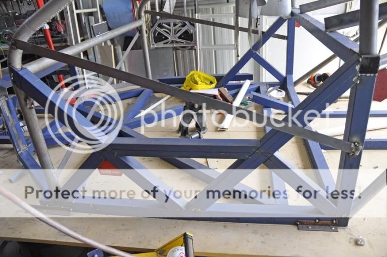
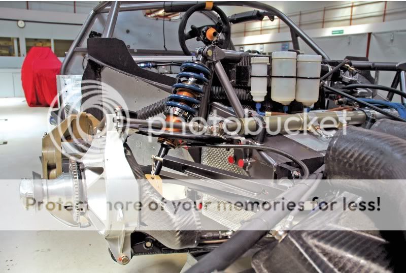
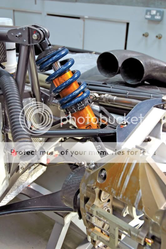
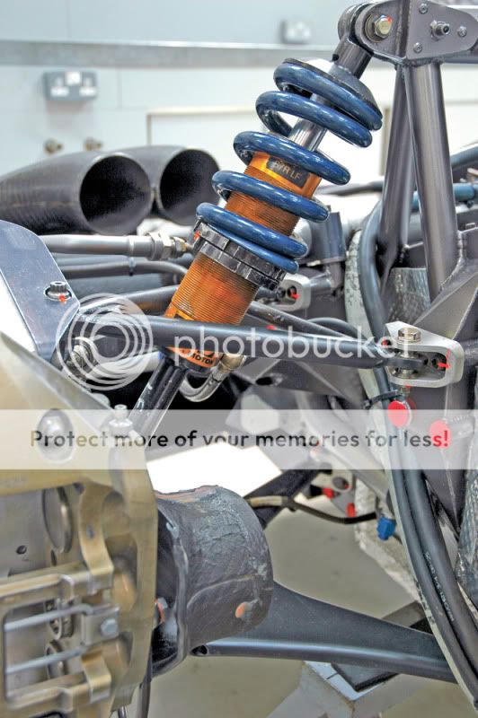
side of chassis needs little help:
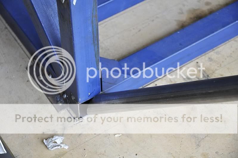
Corner node but weld is where I have concerns - the round tube should be higher than in pic to align with node, but you'll get the idea:
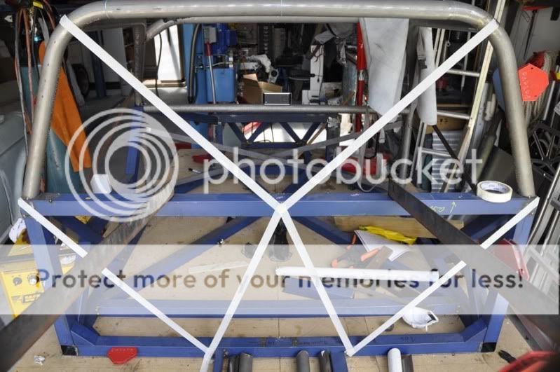
Rear of chassis:
Member
Posted 05 January 2012 - 12:09

Member
Posted 05 January 2012 - 12:24
Some of the classic spaceframe designs have got what appear to be dreadful weak points and that didn't make them any less successful. Even that paragon of the perfectly triangulated chassis, the late C. Chapman took some dreadful liberties - for example on the Lotus 19/Monte Carlo two-seater sportsracer.
Member
Posted 05 January 2012 - 12:29
Of course the other factor is that it is simply easier to make a chassis that will remain straight with bigger tubes during construction, well at least that was the professional advice from one bigger constructor. Larger tubes cope better with weld stresses etc. also at the end of the day an additional 25kg really does not matter.
Member
Posted 05 January 2012 - 12:47
[1] Cap, with 0.020" thicker material, that open square tube first (i.e. make sure it's welded to all 4 sides of that tube).


Edited by cheapracer, 05 January 2012 - 12:47.

Member
Posted 05 January 2012 - 12:49
any reason why you cant go to a larger diameter tube that will join much nicer into the box section ?Moderately serious. I am interested to see how my planned joint fares in Rachel's fea. I cannot continue the tube through the shs as the angle would mean it would go through two adjoining walls and not opposing walls of the shs. It would also be a pain in the arm to do!
Member
Posted 05 January 2012 - 13:20

Member
Posted 05 January 2012 - 13:57
Except for historical curiosity, I don't know why we should give a rat's ass what they were doing with the "classic spaceframe designs." The tire contact patch was smaller than a playing card and the engines produced less output than a current Hyundai Accent. Really, the purpose of the suspension was to prevent the four tires from touching each other while the function of the space frame was to keep the oil pan off the ground. Torsional rigidity was not required while impact safety was utterly irrelevant. Today we have totally different standards and requirements -- much higher ones.


Member
Posted 05 January 2012 - 14:21
I don't see the problem. If you cap the open tube and join the round tube at/near the intersection of the four square tube segments, then weld the round tube 360, you have the cat's ass right there. If you add a doubler (Cheapracer) or two 90-degree gussets (Engineguy) you have medieval war engine capabilities -- ideal for ramming embattlements and so forth. Good to go.
In thinwall construction the problem with a small tube intersecting a large one is that the load is focused on a small area of material in a tearing mode. I don't see that here.
Member
Posted 05 January 2012 - 15:10
100% agree with this

Member
Posted 05 January 2012 - 19:04
The world of bicycle frames might be worth looking at...
I mentioned bike frames not just for the use of lugs, but also double- and triple-butted tubes. I don't know if these have ever been used in automobile chassis.Excellent recommendation. The best solution here is a lug fitting like bike frames use. One end of the lug can fit inside the open end of the square tube, with a perimeter weld. The other end of the lug should fit over the round tube, with a 3D or 4D overlap and a "fishmouth" weld joint. The lug can easily be machined/welded from pieces of plate and round bar.
Advertisement
Tech Forum Host
Posted 05 January 2012 - 19:37
Member
Posted 05 January 2012 - 19:44
I mentioned bike frames not just for the use of lugs, but also double- and triple-butted tubes. I don't know if these have ever been used in automobile chassis.
Member
Posted 05 January 2012 - 20:36
I have cut a 50mm square of the original material and have welded it into the tube 40mm in, bracing all four walls of the tube. The tube will then be capped by the same material (almost creating a steel 'cube') and then a 70mm x 50mm x 2.5mm plate added to where the round tube is but welded.


Member
Posted 05 January 2012 - 21:07
any reason why you cant go to a larger diameter tube that will join much nicer into the box section ?
Edited by NeilR, 05 January 2012 - 21:17.

Member
Posted 05 January 2012 - 21:29
Member
Posted 05 January 2012 - 21:49
Yes. A larger tube will be too big to attach to the damper tube due to the angle and fish mouth required. Yes I could preen the ends over to shorten them, bt the tubes are already generously sized and good enough for the job. In actual fact the 38mm tube at the chassis end when cut makes for a roughly 44mm oval shape.
Kelpie there will be a fairly substantial lower subframe running under the engine and transaxle, which are transverse.
Rachel thanks for that answer. I had considered the weld stresses...what effect would the added plate have. Also what effect would the oblique angle of attachment have?
Member
Posted 05 January 2012 - 22:03
I have a feeling that adding the plate would make it worse - sounds counter-intuitive but the plate will 'break' the stiff load path where the stress concentration is. The joint behaviour will also be non-linear both with load and with load direction as the plate will separate from the box section - difficult to describe but imagine a cardboard tube glued to a piece of card and then the card taped down round the edges to a table. As you push and pull on the tube the card will lean on or pull away from the table depending on the load direction.
RachAEl
Member
Posted 05 January 2012 - 23:17
Well, I've read it a couple of times and I can't see anything about double-butted tubing...Look for posts by McGuire, Cheapracer, and myself in this thread:
Mr. Gasket SS frame lugs...
.
Edited by Tony Matthews, 05 January 2012 - 23:24.
Member
Posted 05 January 2012 - 23:27
In actual fact the 38mm tube at the chassis end when cut makes for a roughly 44mm oval shape.
Member
Posted 06 January 2012 - 01:47
Wow, great thread seeing Wolf and Engineguy posting
I would solve the entire problem with a single cap as shown, ties the corner 3 tubes together, replaces the gusset and spreads the load from the smaller tube - something like 3 or 4mm plate.....

Member
Posted 06 January 2012 - 02:05

Edited by Wolf, 06 January 2012 - 02:32.
Member
Posted 06 January 2012 - 03:01

Member
Posted 06 January 2012 - 04:09
I have a feeling that adding the plate would make it worse - sounds counter-intuitive but the plate will 'break' the stiff load path where the stress concentration is. The joint behaviour will also be non-linear both with load and with load direction as the plate will separate from the box section
Member
Posted 06 January 2012 - 05:05
Greg, not really. The steel is dual grade 350lo/450lo from one steel.
Kelpie, maybe. The thing is I am not comfortable using chapman as a model of current practice. Tyre loads and safety have changed substantially and I would prefer to look at mallock's work on the Saleen cars etc as evidence of good practice. Godiva is sturdy, but then for the obvious reason. Of course the other factor is that it is simply easier to make a chassis that will remain straight with bigger tubes during construction, well at least that was the professional advice from one bigger constructor. Larger tubes cope better with weld stresses etc. also at the end of the day an additional 25kg really does not matter.
Member
Posted 06 January 2012 - 05:43
Member
Posted 06 January 2012 - 06:47
I can post some in a couple oF days. I'm away from my computer at the moment.
Member
Posted 06 January 2012 - 08:34
Member
Posted 07 January 2012 - 03:14
Do you happen to know the measured yield strength of 350 MPa steel in the HAZ?

Member
Posted 07 January 2012 - 09:19
Logic and deduction tell me that you must be near "A" computer of some kind.
Member
Posted 07 January 2012 - 10:42
Advertisement
Member
Posted 07 January 2012 - 11:40
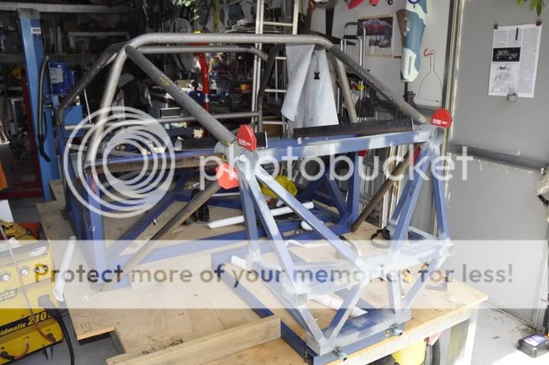
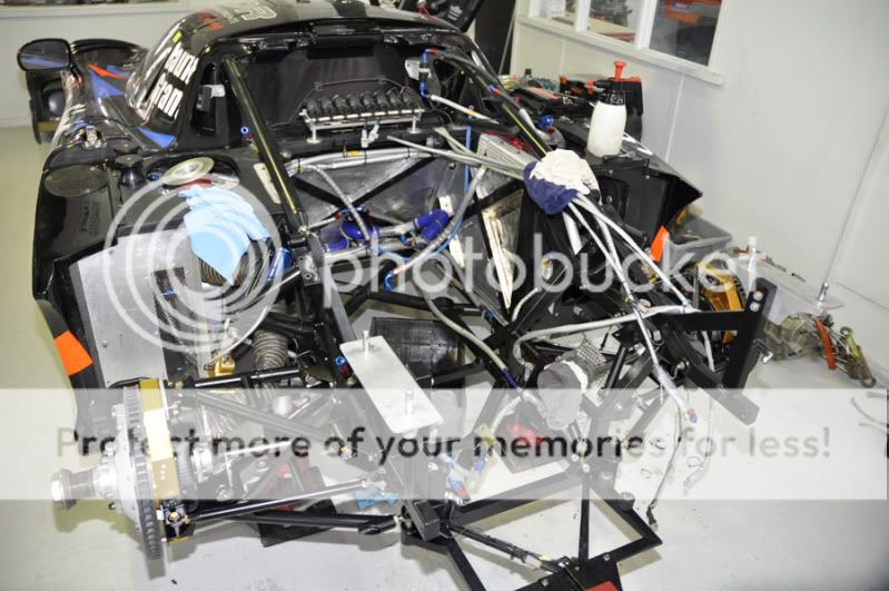
The pictures show a chassis with mostly square tubes, if I understand it correctly square tubes are less efficient then round tubes of the same diameter in terms of weight versus stiffness. The first spaceframes ( aircraft) and early racing car spaceframes were all round tube. Even the US builders of Oval track and drag cars used, mostly, round tubes however bad the frame design was.


© MOTORSPORT NETWORK 2024. All rights reserved. Community Forum Software by IP.Board