Airboxes
#1

Posted 11 December 2012 - 11:24
Not being very technical, I'm confused by some F3 engine controversy in that same year. James Hunt, for example, was disqualified at Brands Hatch for having a 'leaking airbox'. Is this a question of woolly terminology and/or my limited understanding? Were F3 engines sealed around the trumpet area or carburettor to stop air being 'rammed' in? So here 'leaking' would allow more air in, rather than a poorly designed F1 airbox letting air out. Either way, were F3 regs. in place to stop the benefits that the F1 teams were beginning to exploit, or were the F3 airbox issues something entirely different?
Any clarification gratefully received!
Advertisement
#2

Posted 11 December 2012 - 11:50
#3

Posted 11 December 2012 - 12:13
My understanding is that F3 airboxes, in the 2 litre F3 era, had a specified maximum diameter inlet to control the amount of power the cars could produce, as a consequence leaky airboxes were frowned upon and penalised, I had no idea that this went as far back as James Hunts time when airboxes had yet to appear in F3, but I suppose there may have been a restriction on the width of the carburetor air intake.
Thanks arti. It was an issue at least as early as 1971 (WCVR race at Brands, October 1971) and, although the F3 cars didn't have the F1 vertical air scoops that year, these photos on the F3history site might help. Presumably, in the 1971 March photos, the side mounted tubular scoops mounted over the inlets are creating the same effect as the more visible GP airboxes, although I still don't really understand why a leaky airbox, maximum diameter inlet or not, would give a performance advantage. Unless faster flowing air passing over the trumpets, caused by a unit leak, works better for some reason. As you can tell, I didn't take Physics to degree level........
http://www.f3history...March/march.htm
Edited by john winfield, 11 December 2012 - 12:13.
#4

Posted 11 December 2012 - 12:42
The function of an airbox without an orifice is different. It is intended primarily to convert dynamic pressure to static pressure. In addition, nowadays it is typical to use CFD to optimise the shape of the airbox to damp internal pressure pulses caused by the wave reflections at the mouths of the trumpets, to minimise the effect on adjacent trumpets.
Edited by Nigel Beresford, 11 December 2012 - 12:44.
#5

Posted 11 December 2012 - 13:03
In simple terms, the fastest rate at which air can flow through an orifice is the speed of sound. These orifices therefore limit the maximum amount of air an engine can draw in, and therefore limit power. A leak in the airbox allows additional air to be drawn in, thus adding power.
The function of an airbox without an orifice is different. It is intended primarily to convert dynamic pressure to static pressure. In addition, nowadays it is typical to use CFD to optimise the shape of the airbox to damp internal pressure pulses caused by the wave reflections at the mouths of the trumpets, to minimise the effect on adjacent trumpets.
Nigel, thank you. 'In simple terms' it may be, but I'm still confused! Sticking to 1971, both Grand Prix and F3 cars appear to have air scoops which route the flow of air into airboxes. Are the F3 devices, imposed presumably by regulations, designed to restrict air intake? (suggesting that more air could have been sucked in, without the box, from the flow of air alongside the car) On the other hand, are the F1 scoops the result of engineers deciding that, possibly, the increased amounts of enclosed aerodynamic bodywork meant that naturally available airflow was becoming limited, so diverting air through scoops (of restricted diameter or not) was necessary? To this layman the airboxes, both with orifices, in two different formulae, appear to achieve opposite results.
Edited by john winfield, 11 December 2012 - 13:06.
#6

Posted 11 December 2012 - 13:28
Nigel, thank you. 'In simple terms' it may be, but I'm still confused! Sticking to 1971, both Grand Prix and F3 cars appear to have air scoops which route the flow of air into airboxes. Are the F3 devices, imposed presumably by regulations, designed to restrict air intake? (suggesting that more air could have been sucked in, without the box, from the flow of air alongside the car) On the other hand, are the F1 scoops the result of engineers deciding that, possibly, the increased amounts of enclosed aerodynamic bodywork meant that naturally available airflow was becoming limited, so diverting air through scoops (of restricted diameter or not) was necessary? To this layman the airboxes, both with orifices, in two different formulae, appear to achieve opposite results.
I tried to find a contemporary picture of a 1971 F3 car which clearly showed the airbox, but (surprisingly) Autocourse didn't seem to pay it any attention to it. However, there are some decent pics in the '72 book which show F3 airboxes with restrictors, which obviously must have been prescribed by the rules. So, yes, they were designed to restrict air intake and therefore power. The use of inlet restrictors, whilst it offends (us) purists, is a cheap and easily regulated (and easily changed) way for governing bodies to control and/or balance performance.
The F1 airboxes of the time didn't (and never have) featured inlet restrictors. Indeed, there was a short period in the first part of 1995 when teams were obliged to cut a hole in the back of the airbox to limit its ability to build static pressure and thereby limit power. F1 airboxes then and now worked by capturing fast moving air and slowing it down so that it regains static pressure, which obviously means that it will then flow more readily in to the engine and hence improve volumetric efficiency and thereby power. Before the advent of the airbox the engine was drawing its air from the turbulent wake behind the driver's helmet and the roll over hoop. The airbox cleaned this up, and probably helped clean up the flow to the rear wing too. The problem, as mentioned elsewhere before, is that the DFV wasn't really designed to accommodate an airbox, and it took a while for people to develop trumpet and tray designs which allowed a proper seal to be obtained, and therefore maximise the effect.
Of course, the fundamental difference between the F3 and F1 applications is that in the former a leak will gain you power, whilst in the latter it will lose you power.
Here's a nice example of a sealing tray from the late Eighties:

Edited by Nigel Beresford, 11 December 2012 - 13:38.
#7

Posted 11 December 2012 - 13:38
Roger Lund
#8

Posted 11 December 2012 - 13:42
Nigel, I came across a nice shot of Don Beresford working on the McLaren M2A in a Classic Cars 1994 issue this morning in the MOT garage reception area.
Roger Lund
That's the mallite car - I still have a small sheet of that stuff on the wall in my garage - my dad used it to make a sticker board for me back in '67!
#9

Posted 11 December 2012 - 13:45
The F1 airboxes of the time didn't (and never have) featured inlet restrictors.
They did, in 2006. 2.4 V8, OR 3.0 V10 with a restrictor.
#10

Posted 11 December 2012 - 13:46
#11

Posted 11 December 2012 - 14:03
I tried to find a contemporary picture of a 1971 F3 car which clearly showed the airbox, but (surprisingly) Autocourse didn't seem to pay it any attention to it.
Does the third picture here in the 1971 batch, a Holbay engine in a March 713, show what you want?
http://www.f3history...March/march.htm
Edited by john winfield, 11 December 2012 - 14:03.
#12

Posted 11 December 2012 - 14:05
#13

Posted 11 December 2012 - 14:09
Does the third picture here in the 1971 batch, a Holbay engine in a March 713, show what you want?
http://www.f3history...March/march.htm
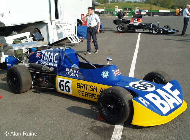
I don't think that shows it. Scroll down a bit to the picture of Keegan's car for a better example.
#14

Posted 11 December 2012 - 14:13
Just to add a little to what Nigel has already said: In 1971 F3 changed from the 1000cc ‘screamers’ to 1600cc with restrictor. This was the first time such a device had been mandated in any major single-seat formula. All the air entering the engine had to pass through this restricting orifice, initially set at 20mm diameter but soon increased to 21.5mm as the smaller hole was too restrictive. This restrictor was deliberately sized to (as its name suggests) restrict air mass flow into the engine and hence power output. As Nigel has pointed out, once the flow through this orifice reaches sonic velocity no further increase in mass flow can be achieved no matter how much the pressure drop across the orifice is increased. Thus there was every advantage to be gained by having slightly less-than-airtight airboxes downstream of the restricting orifice, as then more air could be got into the engine.
Tim, Nigel, thanks very much. The purpose and design of these different airbox devices are now much better understood!
#15

Posted 11 December 2012 - 14:17
I don't think that shows it. Scroll down a bit to the picture of Keegan's car for a better example.
I see what you mean. In the first of the 1971 pictures, is that the restrictor projecting beyond the line of Roger Williamson's roll-hoop? If so, is the Holbay engine in the close-up waiting to have the narrow diameter restrictor fitted to that wider visible orifice?
#16

Posted 11 December 2012 - 15:24
Yes, that's definitely it. Here's a photo of a much more modern Toyota F3 engine, but the restrictor principle is the same:I see what you mean. In the first of the 1971 pictures, is that the restrictor projecting beyond the line of Roger Williamson's roll-hoop?
http://www.motorspor...eb25d469619d135
#17

Posted 11 December 2012 - 18:10

Edited by Nigel Beresford, 11 December 2012 - 18:11.
#18

Posted 12 December 2012 - 08:57
#19

Posted 12 December 2012 - 08:58
If I remember it, Joe advanced it as the only restriction (in any sense) to be placed on the design of a car - in other words you could put what you liked downstream of the hole (which had to be in ambient pressure/temperature).
Advertisement
#20

Posted 13 December 2012 - 03:28
Thanks
#21

Posted 13 December 2012 - 07:36
I don't think that shows it. Scroll down a bit to the picture of Keegan's car for a better example.
Ironically, I believe the current owner of that car discovered the air restrictor that came with the car was illegal! (Not that I'm implying it was like that when Keegan raced it).

#22

Posted 13 December 2012 - 08:39
Ironically, I believe the current owner of that car discovered the air restrictor that came with the car was illegal! (Not that I'm implying it was like that when Keegan raced it).
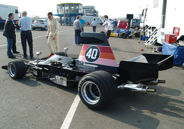
Alan, interesting photo, showing the two sides of the airbox issue that had always confused me! The neat restrictor on the F3 March, and the huge air scoop on...what is that?.... an F5000 Lola? Doubt if the Lola's airbox has a good seal as I see no bungee rope.
#23

Posted 13 December 2012 - 10:32
Alan, interesting photo, showing the two sides of the airbox issue that had always confused me! The neat restrictor on the F3 March, and the huge air scoop on...what is that?.... an F5000 Lola? Doubt if the Lola's airbox has a good seal as I see no bungee rope.
It's a Lola T330. In this case the airbox is blended into the bodywork.


