Jump to content


Photo
- - - - -

PatDan CVJ


  • Please log in to reply
36 replies to this topic

#1 manolis

manolis
  • Member

  • 935 posts
  • Joined: May 03

Posted 25 March 2014 - 04:37

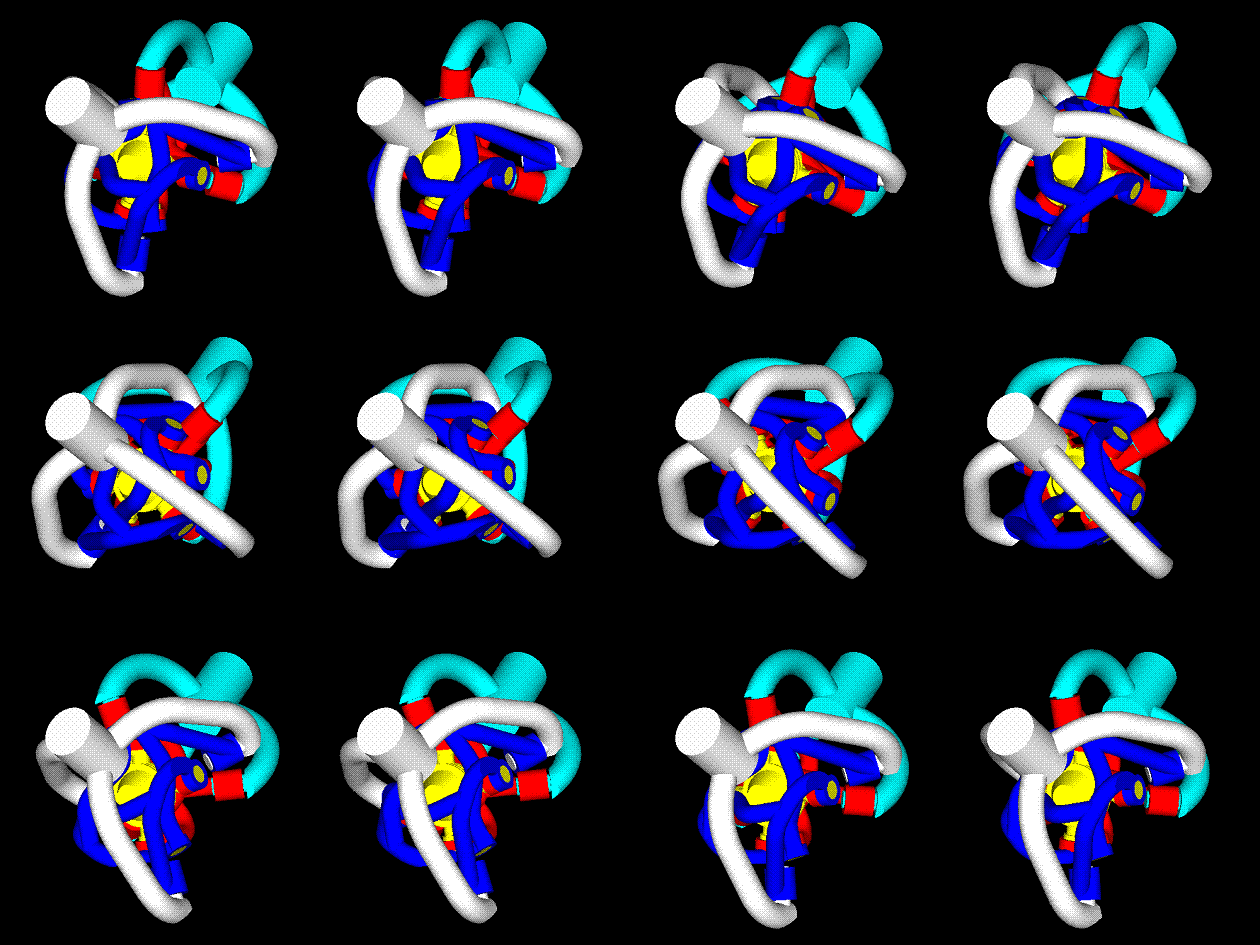
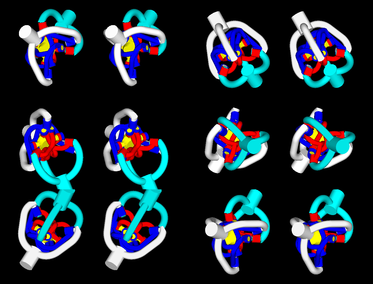
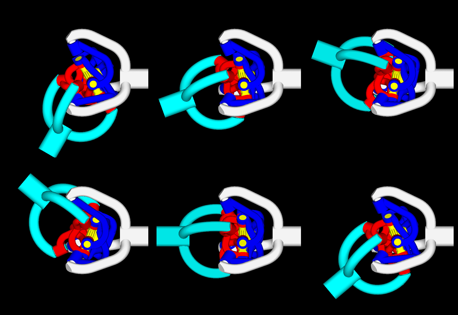
PatDan CVJ: a low-friction drive-shaft CVJ (Constant Velocity Joint) for extreme steering angles.

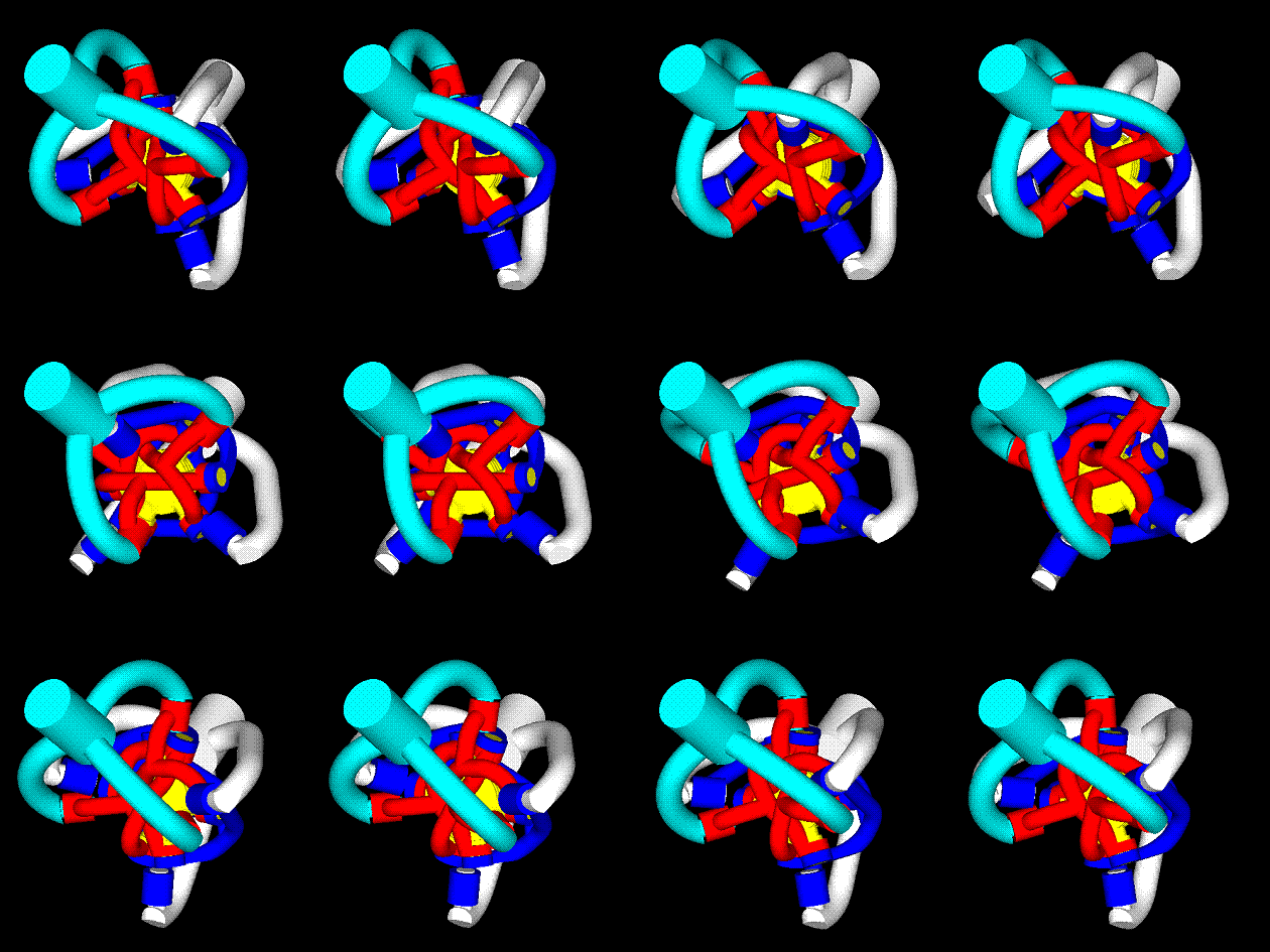
In case you cannot see the following animations stereoscopically (how? click on http://www.pattakon....Stereoscopy.htm ), just focus on the left or on the right image.
However, if a member of the forum does achieve the stereoscopic viewing, he/she is kindly requested to explain to the rest what they lose.

PatDan5.gif

PatDan6.gif

PatDan7.gif

The angle between the shafts of the PatDan CVJ is 60 degrees in the animations (and can be bigger).
In comparison the world's highest maximum operating angle of the Rzeppa CV joints of the automobile drive shafts is only 54 degrees (while the conventional design of the Rzeppa CV joint limits the maximum operating angle to less than 50 degrees).

PatDan_turn.gif

The PatDan CV joint is based on roller bearings and is rid of loaded sliding surfaces.
In comparison the Rzeppa CV joint is based on heavily-loaded sliding surfaces wherein balls slide.
For the same wide angle between the shafts, the PatDan is by far more efficient than the Rzeppa CV joint (the first runs cold while the second soon overheats).

The PatDan has the qualifications to substitute the Rzeppa CV joints in the automobile drive shafts: true constant velocity joint, way more efficient, greater-steering-angles / smaller-turning-radiuses.


By the way, the PatDan can take heavy axial loads (mandatory in other applications, as in helicopters for instance) while the Rzeppa CV is not for axial loads.

For more: http://www.pattakon....takonPatDan.htm

Thanks
Manolis Pattakos

Advertisement

#2 Kelpiecross

Kelpiecross
  • Member

  • 1,730 posts
  • Joined: October 10

Posted 25 March 2014 - 10:10


I think I would have to study the workshop manual very carefully before I pulled your new joint apart.

But if it works as you describe it would be very useful. Not too big is it - compared to a Rzeppa? The Thommo CV joint looks good but it appears to be only about 15 degrees.

#3 blkirk

blkirk
  • Member

  • 319 posts
  • Joined: March 00

Posted 25 March 2014 - 15:30

I can't get the stereo thing to work for me, but I still think I have a pretty good idea of how it goes together.  It looks like the light blue/cyan shaft end and the white shaft end are identical.  There are 3 dark blue links and three red links.  All six of them are nearly identical.  The yellow puck in the middle has six arms.  Each arm has a pivot from a red link and a dark blue link. 


It occurred to me that the dark blue links and the red links can't be identical since the red links are always closer to the center of the yellow puck than the dark blue links.  Would the geometry still work out if one arm was a little longer than the other so that the red and dark blue links alternated which one went on the yellow puck first?  Have you worked through the order of operations to assemble this thing?  It looks like it would be very easy to get into a spot where you don't have enough range of motion to get one of the pivots to slide on.


#4 manolis

manolis
  • Member

  • 935 posts
  • Joined: May 03

Posted 25 March 2014 - 18:42

I can't get the stereo thing to work for me, but I still think I have a pretty good idea of how it goes together. It looks like the light blue/cyan shaft end and the white shaft end are identical. There are 3 dark blue links and three red links. All six of them are nearly identical. The yellow puck in the middle has six arms. Each arm has a pivot from a red link and a dark blue link.
It occurred to me that the dark blue links and the red links can't be identical since the red links are always closer to the center of the yellow puck than the dark blue links. Would the geometry still work out if one arm was a little longer than the other so that the red and dark blue links alternated which one went on the yellow puck first? Have you worked through the order of operations to assemble this thing? It looks like it would be very easy to get into a spot where you don't have enough range of motion to get one of the pivots to slide on.


Blkirk,

The cyan shaft and the white shaft are not identical (spot on the three pivot axes – actually the bearings - in each one of them). It is easier to see the difference in the last animation. The center of the CV joint is at the yellow assembly, where the axes of the three yellow “beams” intersect. The three pivot axes of the left shaft (cyan) lean to the left. The three pivot axes of the right shaft (white) lean also to the left.

The yellow assembly at the center comprises three arms (three beams) pivotally mounted to each other to pivot about a common axis (say about a common central pin). Imagine thee cans connected at their centers by a pin nail (as in some kites); the pin nail is the “common axis”.

The geometry has nothing to do with the length of the arms; it has to do only with the angles of the pivot axes. I.e. the geometry still works if one arm is longer than the others; and it doesn’t matter which link (the red or the blue) is closer to the center of the joint. For instance, at the one end of the one (of three) yellow beam the red link can be near to the center, while at the other end of the same yellow beam the same red link can be far from the center, with the CV joint still operating normally.

For the assembly: the red and blue arms are initially assembled on the cyan and white shafts respectively; then the three “yellow” beams are inserted and bridge the red links with the blue links; the rollers bearings are then inserted between the red – blue – yellow parts; then the roller bearings of the yellow assembly are inserted in their place; then the roller bearings between the red links and the cyan shaft (and between the blue links and the white shaft) are inserted; finally the “common pin” is inserted securing the complete mechanism (the common pin is normal to the three yellow “beams” and acts like the “key” of the CV joint).

Thanks
Manolis Pattakos

#5 Fondles

Fondles
  • Member

  • 52 posts
  • Joined: July 11

Posted 25 March 2014 - 21:25

Similar to the Thompson Coupling .... ?


http://www.thompsoncouplings.com/


#6 NotAPineapple

NotAPineapple
  • Member

  • 715 posts
  • Joined: July 13

Posted 25 March 2014 - 22:19

Doesn't look like it can support axle plunge unless another sliding part is added, which would kind of wreck the whole point of the joint...


#7 Greg Locock

Greg Locock
  • Member

  • 6,364 posts
  • Joined: March 03

Posted 25 March 2014 - 22:34

The Thomson coupling is an overhyped slight derivative of a double cardan. The idea of stabilising the floating section has been around for donkey's years, the Thomson is merely one implementation of that.


Manolis although your work on engines is much more interesting I think you should pursue this, as you know auto manufacturers almost always use the full articulation available. The first problem is that OEMs don't actually do any design work any more, so your best way in would be via the transmission components people, NTN and the like.


#8 John Brundage

John Brundage
  • Member

  • 309 posts
  • Joined: July 08

Posted 25 March 2014 - 22:52

How much radial torque can this design handle?


#9 manolis

manolis
  • Member

  • 935 posts
  • Joined: May 03

Posted 26 March 2014 - 05:37

Fondles,

The Thompson coupling is different.
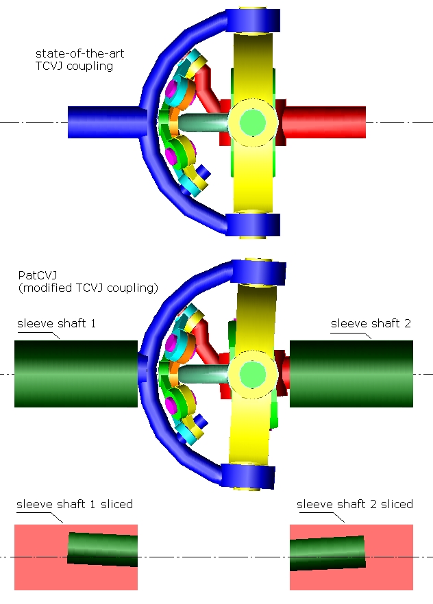
TCVJtoPatCVJ.jpg

The Thomson coupling (TCVJ) is shown at top.
According the inventor and maker of the TCVJ coupling, a minimum angle of two degrees between the shafts is required, otherwise the parts of the TCVJ coupling rapidly wear.

The TCVJ is for small angles between the driving and driven shafts (some models are for 15 degrees, some other for no more than 10 degrees). Imagine putting in the middle of an already narrow range of angles another limitation not allowing angles from –2 to +2 degrees. What is left?

Under the TCVJ, in the figure above, it is a modification (we call it PatCVJ) that solves this problem of the TCVJ. The pivot axes A1 and A2 are oblique to the rotation axes of the respective shafts. The PatCVJ is already patented in the UK; in the US the patent has already been approved and is to be granted in a few weeks.

Both, the PatCVJ and the TCVJ comprise a main set of yokes and an auxiliary set of yokes / links.
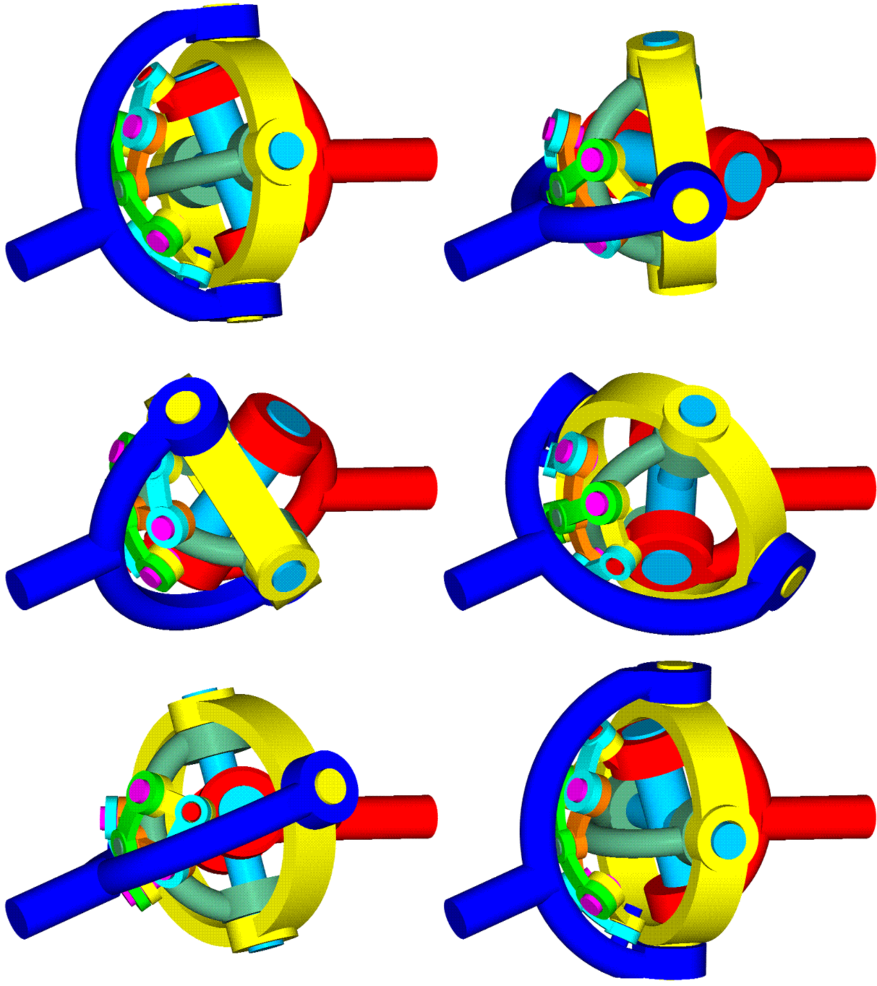
PatCVJ.gif

The "main set of yokes" comprises:
a first yoke (the cyan cross at the center, in the animation above) pivotally mounted to a first shaft (the red shaft),
a second yoke (the yellow ring-cross) pivotally mounted to a second shaft (the blue shaft),
and a "control" yoke (the dark green fork) which is pivotally mounted to said first yoke and to said second yoke so that the three yokes of the "main set of yokes" pivot about a common axis.

The three "main yokes" make the hard work of transferring the torque load and the axial load from the one shaft to the other.

The "auxiliary set of yokes" comprises six articulated arc-shaped links (or yokes) that constitute a spherical pantograph mechanism (the two yellow links, the two cyan links, the green "rocker" link and the brown "rocker" link in the above animation). The one end of the pantograph pivots about an oblique pin of the first shaft, the other end of the pantograph pivots about an oblique pin of the second shaft. The center of the spherical pantograph keeps the "control" yoke at the right orientation so that the transmission ratio remains strictly at 1:1.

The PatDan Constant Velocity Joint is different.
It comprises three "main sets of yokes" like the abovementioned, and none "auxiliary set of yokes".
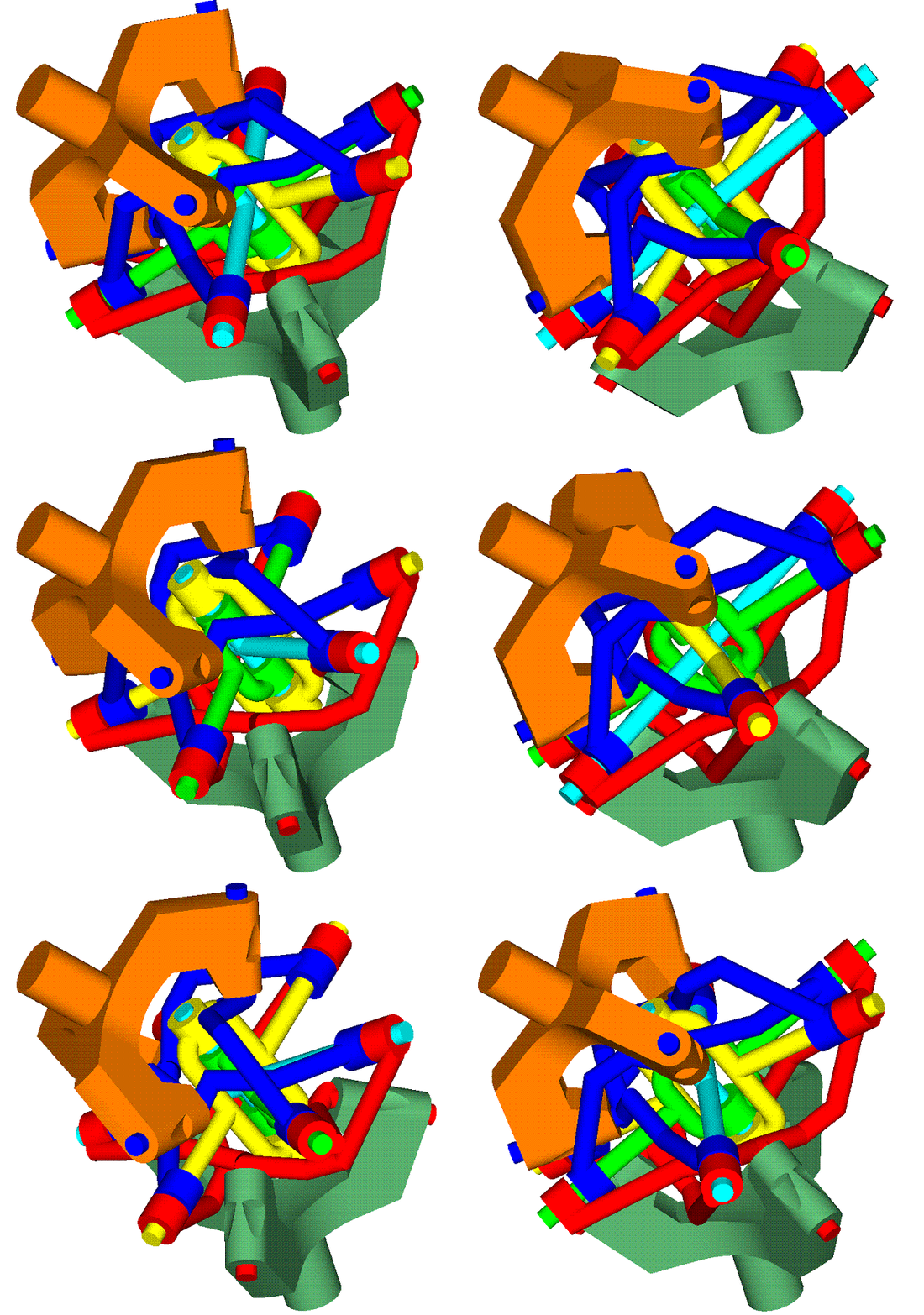
PatDan.gif

The three "control" yokes (the green, the yellow and the cyan crosses at the center of the animation above) are pivotally mounted to each other so that they pivot about a common axis.
The rest yokes are forks (the blue ones are pivotally mounted to the upper / brown shaft, the red ones are pivotally mounted to the lower / dark green shaft).
The forks are properly bend to allow wider angles of operation.
The torque load and the axial load split among all yokes.
The PatDan can take heavy axial loads.
So, the PatCVJ is similar to the TCVJ of the Australian Thompson Coupling, but the PatDan CVJ is quite different.


NotAPineapple:
The PatDAN shown in the stereoscopic animations fits to wide angles and to axial loads as is. But if you want to take heavy axial loads, crosses supported at both ends can substitute the red and blue yokes (or links), as in:
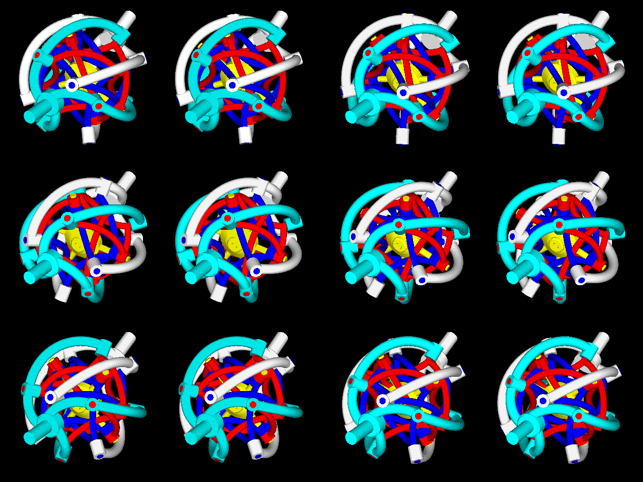
PatDan_7.gif

Can you, please, explain what you mean by: “Doesn't look like it can support axle plunge unless another sliding part is added”. Does a Rzeppa CV joint need "another sliding part to be added"?


Greg Locock:
Geometrically speaking, the PatDan is a very interesting and, at the same time, complicated problem. For instance, try to figure out the angle between the pivot axes and the respective shaft axes in order to achieve an operating angle range between, say, 0 and X degrees between the driving / driven shafts.

Thanks for mentioning the NTN.
At http://www.ntn.co.jp...R75_en_P016.pdf (pdf of 2007) NTN explains the steps/modifications they did in order to increase the highest maximum operating angle of the Rzeppa CV joints of the automobile drive shafts to 54 degrees. With the PatDan we can have, at once, more than 60 degrees, with several times lower friction.


John Brundage:
What do you mean by radial torque? There is a torque passing from the one shaft to the other, there is also an axial load passing from the one shaft to the other. The limiting factor is the strength of the yokes / shafts involved and the static / dynamic loads the roller bearings can bear.

Thanks
Manolis Pattakos
#10 MatsNorway

MatsNorway
  • Member

  • 2,822 posts
  • Joined: December 09

Posted 26 March 2014 - 08:00

Done any FEM analysis? i would love to try ;) And it looks more doable than your other designs. step file is prefered.


#11 manolis

manolis
  • Member

  • 935 posts
  • Joined: May 03

Posted 26 March 2014 - 17:53

Done any FEM analysis? i would love to try ;) And it looks more doable than your other designs. step file is prefered.


Hello Mats.
The drawing of the PatDan CVJ (in dxf format) was emailed to you a few minutes ago.
Thanks
Manolis Pattakos
#12 NotAPineapple

NotAPineapple
  • Member

  • 715 posts
  • Joined: July 13

Posted 26 March 2014 - 19:22

What I mean by plunge is that as the wheel moves up and down, the distance between the inner and outer CV joints changes. In a typical CV joint the load bearing assembly in the joint slides axially in the housing to account for this. I.e. it has built in axial free play.


It looks to me like your solution is fixed on both ends so how would it account for required change in inner to outer joint distance?


#13 Greg Locock

Greg Locock
  • Member

  • 6,364 posts
  • Joined: March 03

Posted 26 March 2014 - 23:49

You don't use that style of joint at the inboard end of the halfshaft because it only needs a lot of vertical articulation, say 20-30 degrees, whereas the outboard end has to cope with steer as well 45 degrees or more, which is much greater angles. I agree, you do need plunge somewhere, but it should not be in the most complex joint.


#14 manolis

manolis
  • Member

  • 935 posts
  • Joined: May 03

Posted 27 March 2014 - 05:24

What I mean by plunge is that as the wheel moves up and down, the distance between the inner and outer CV joints changes. In a typical CV joint the load bearing assembly in the joint slides axially in the housing to account for this. I.e. it has built in axial free play.
It looks to me like your solution is fixed on both ends so how would it account for required change in inner to outer joint distance?


Hello NotAPineapple.

If after the explanation of Greg Locock you are still confused, please take a look at the drawing at the bottom right of the first page of the http://www.ntn.co.jp...R75_en_P016.pdf review of NTN. It shows a drive shaft with a "fixed" CVJ (a Rzeppa CV joint) near the tyre and a plunging CVJ near the differential. This is the conventional architecture in all front wheel drive cars.

By the way, did anyone achieve the stereoscopic viewing?

Thanks
Manolis Pattakos

#15 Kelpiecross

Kelpiecross
  • Member

  • 1,730 posts
  • Joined: October 10

Posted 27 March 2014 - 06:04


Manny - I may be a little dim but I have to admit that I am not quite sure how it all works. Is the PatDan equivalent to a three-ball/three groove Rzeppa with the common axis of the green/yellow/cyan crosses acting as the equivalent of the Rzeppa "cage"? Did you develop your PatDan idea from a modification of a Rzeppa to replace the higher-friction balls/grooves with lower-friction roller bearings?

The "stereoscopic" images are interesting. I find that by focussing my eyes at distance (infinity) between the two images a third image does form (with a bit of practice) between the left and right images which neatly combines the two images. But I didn't find it especially useful.

How about rotating images that can be "frozen" and maybe separate images of each component?

My mechanically-ignorant son thinks it looks like an "octopus wrestling death match" - he has got a point.

#16 manolis

manolis
  • Member

  • 935 posts
  • Joined: May 03

Posted 27 March 2014 - 07:09

Manny - I may be a little dim but I have to admit that I am not quite sure how it all works. Is the PatDan equivalent to a three-ball/three groove Rzeppa with the common axis of the green/yellow/cyan crosses acting as the equivalent of the Rzeppa "cage"? Did you develop your PatDan idea from a modification of a Rzeppa to replace the higher-friction balls/grooves with lower-friction roller bearings?


Hello Kelpiecross.

I would rather say that the PatDan is the evolution of the Thompson coupling (TCVJ) and the likes: the "auxiliary set of yokes" (which comprises six yokes and which causes several problems) is replaced by two triads of yokes (again six yokes in total).
Instead of having some yokes for the transferring of the loads and some others for the orientation of the other ones, in the PatDan CVJ the loads and the orientation are shared among all yokes.

I could also say that the architecture of the PatDan is symmetrical in the space and fits to the three dimensions. In comparison, the TCVJ and the PatCVJ have a "preferable" plane / direction (say the plane wherein the forks of the two shafts are on, when the shafts are at a straight line).

On the other hand, what really matters is whether or not:
the PatDan is a true CVJ,
the PatDan is capable for bigger angles between the shafts,
the PatDan is rid of heavily loaded sliding surfaces (which means a several times less friction as compared to the current state-of-the-art Rzeppa CV joint),
the PatDan can transfer heavy torque loads,
the PatDan can take heavy axial loads.
If yes, there are many applications for the PatDan (from driveshafts, to helicopters).


The "stereoscopic" images are interesting. I find that by focussing my eyes at distance (infinity) between the two images a third image does form (with a bit of practice) between the left and right images which neatly combines the two images. But I didn't find it especially useful.


You did all the way to see stereoscopically.
Just ignore the two side images (if necessary hide them by your palms as explained at http://www.pattakon....Stereoscopy.htm )

On the other hand, the PatDan is a complicated mechanims (not the best to start seeing stereoscopically).
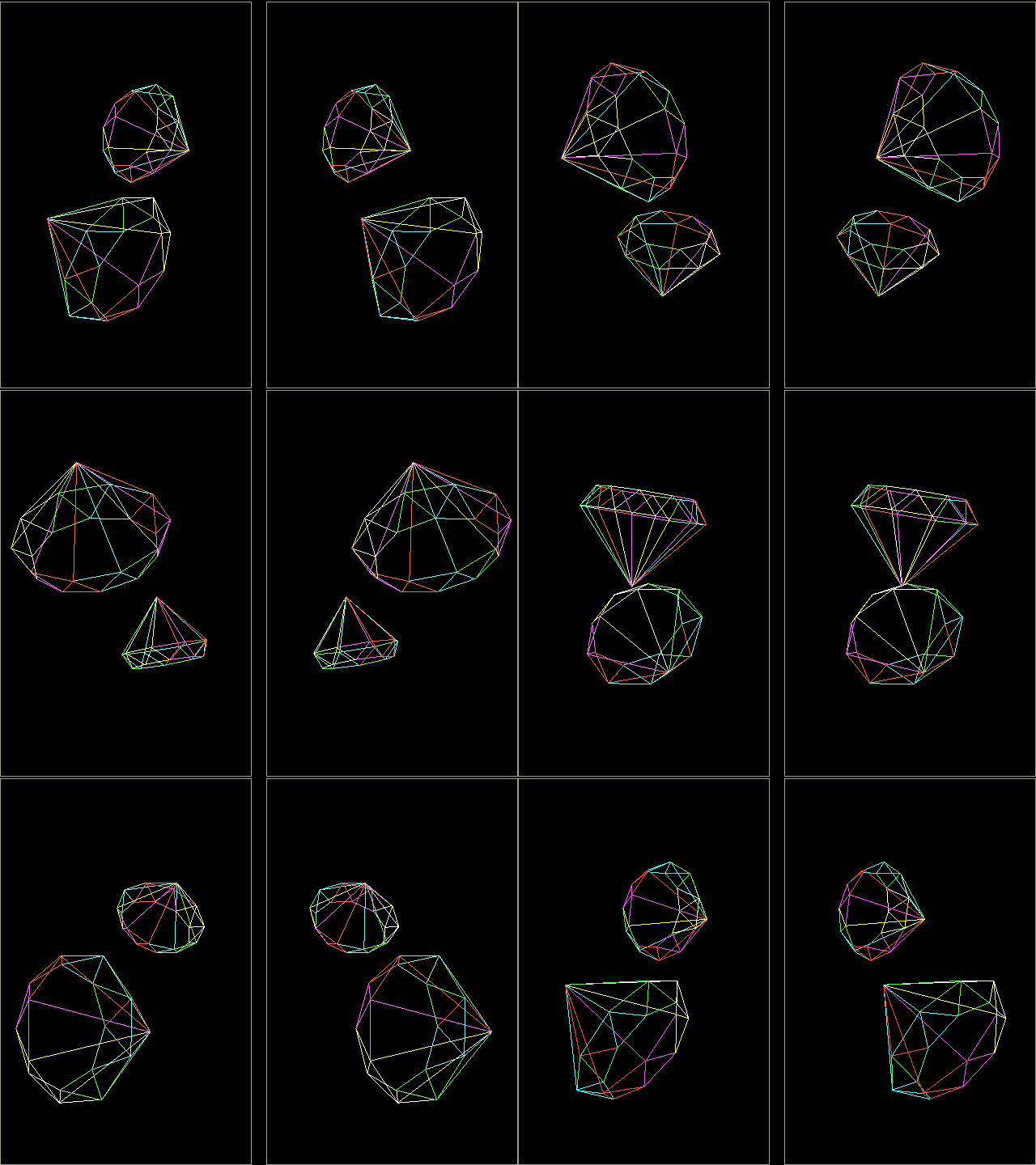
Try this:

Diamonds.gif

and let me know.

Thanks
Manolis Pattakos
#17 RogerGraham

RogerGraham
  • Member

  • 183 posts
  • Joined: October 12

Posted 27 March 2014 - 08:25

Manolis, do you see any negatives in the design of your PatDan CVJ (e.g. weight or cost or size or...)?


#18 manolis

manolis
  • Member

  • 935 posts
  • Joined: May 03

Posted 27 March 2014 - 09:22

Manolis, do you see any negatives in the design of your PatDan CVJ (e.g. weight or cost or size or...)?


Hello RogerGraham.


I don't think PatDan will weight more than an equivalent Rzeppa CVJ, nor that it is more expensive or substantially bigger (there is space in the drive shafts for a little bigger diameter).


While with traditional tools I cannot manufacture a good Rzeppa CV joint,  I can make a good quality PatDan prototype.


The true negative I see in the PatDan (and in other concepts of pattakon) is that it comes not from the existing manufactures.


Take for instance  the PatMar concept at http://www.pattakon....takonPatMar.htm .

It solves an existing problem.


The problem as defined in Wartsila's(*) Technical Journal, Feb 2010 (click here for the article):
"A slightly more ambitious idea is to apply the four-stroke trunk piston engine cylinder lubrication concept to the two-stroke crosshead engine, i.e. to "over-lubricate" the cylinder liner, apply an oil scraper ring, and then collect the surplus oil, clean it, and recycle it. This will of course be a radical change of concept, and whether or not it is viable remains to be demonstrated, but an outline exists and a patent is pending. The aim is to increase scuffing resistance and to achieve the same low specific oil consumption level as on the four-stroke trunk piston engines."

                                                                       (*) Wartsila is a global leader in complete lifecycle power solutions for the marine and energy markets


The solution: The PatMar engine applies the four-stroke trunk piston engine cylinder lubrication concept to the two-stroke crosshead engine, i.e. it "over-lubricates" the cylinder liner, applies an oil scraper ring, and then collects the surplus oil, cleans it, and recycles it.
The PatMar not only increases the scuffing resistance of the two-stroke engines, but it achieves the same scuffing resistance as on the four-stroke trunk piston engines.
The PatMar achieves the same low specific oil consumption level as on the four-stroke trunk piston engines.


With the patents granted by the USPTO and by the UK-IPO we tried to communicate with the Wartsila's R&D. They simply refuse to respond (please try to ask them why). They could save a lot of money. The big container ships consume typically more than 500.000 dollars per year for the oil consumed for the cylinder lubrication, which then pollutes the atmosphere. They could save even more money by eliminating the mechanism that brings the oil to the cylinders. They could also save a lot of money by the substantially extended intervals between overhauls.


We can't make a big prototype for the PatMar; we are working on a 1.2lt per cylinder PatMar (210mm stroke). In the four-in-line version it could be used in trucks.


If the invention was made by Wartsila or MAN (the two manufacturers of the marine giant two stroke engines) I am sure it would be presented as "the evolution" for the marine communications (and the power generating stations) in every magazine, newspaper and forum around the world. Don't you think?


Similarly, if the PatDan was owned by NTN, I am sure it would be in the drive shafts of FWD cars for tests in a few days.


Thanks

Manolis Pattakos


#19 Kelpiecross

Kelpiecross
  • Member

  • 1,730 posts
  • Joined: October 10

Posted 28 March 2014 - 06:42


Manny - I find that while the "bundle of snakes" PatDan images work well I can't really get the "diamonds' to work at all - they combine at the smaller size and separate as they get bigger. Nor can I get the covering each eye trick to work - I need both images/both eyes. I did a lot of microscope work at uni and we were advised that it was best to keep both eyes open and ignore the image from the eye that wasn't looking down the barrel of the microscope. I found it best to use the micro in this fashion - but I think most students didn't.

Are these images truly stereoscopic (that is; slightly different as seen by each eye) or just two identical images? It makes me wonder if 3-D viewing of TV (with two separate screens etc.) may be possible - more money in that than a PatDan I would guess.

What I was thinking about the PatDan being a little like a Rzeppa joint was that I think if a single-ball Rzeppa is possible (if not very practical) a similar very simplified version of the PatDan may also be possible. A few scribbles on paper make me think that such a simplified PatDan might work.

Advertisement

#20 manolis

manolis
  • Member

  • 935 posts
  • Joined: May 03

Posted 28 March 2014 - 13:39

Manny - I find that while the "bundle of snakes" PatDan images work well I can't really get the "diamonds' to work at all - they combine at the smaller size and separate as they get bigger. Nor can I get the covering each eye trick to work - I need both images/both eyes. I did a lot of microscope work at uni and we were advised that it was best to keep both eyes open and ignore the image from the eye that wasn't looking down the barrel of the microscope. I found it best to use the micro in this fashion - but I think most students didn't.
Are these images truly stereoscopic (that is; slightly different as seen by each eye) or just two identical images? It makes me wonder if 3-D viewing of TV (with two separate screens etc.) may be possible - more money in that than a PatDan I would guess.
What I was thinking about the PatDan being a little like a Rzeppa joint was that I think if a single-ball Rzeppa is possible (if not very practical) a similar very simplified version of the PatDan may also be possible. A few scribbles on paper make me think that such a simplified PatDan might work.


Hello Kelpiecross.


I think you try to see the left image by your left eye and the right image by your right eye. This is wrong.

To see the diamonds stereoscopically, just hide the left image from your left eye and the right image from your right eye by your palms (put your palms at a distance, say, 10cm from your head, and at a distance, say, 5cm from each other) and then try to concentrate your sight on a small object located at the intersection of the line from your left eye to the right figure and the line from your right eye to the left image.

The "software" is already into your brain waiting for activation.

Just follow the instructions above and try again.


The left and right images are different.

If you look carefully, you can see the differences.

For instance, see the following transparent "cube"


image002.gif


Take the letter P (of the Pattakon) which is exactly over the G (of the Greece) at the left side of the left image; the respective P (of the Pattakon) in the right image is substantially displaced to the right of the G (of the Greece). The differences are translated by the brain. The brain knows how.


"The 3-D viewing of TV (with two separate screens etc.)" is, for sure, possible. Actually you do not need two TV sets: in a window at the left side of the TV you have the one "movie" playing and in a window at the right side of the same TV you have the other "movie" playing. That is all you need. 

For the money you write, let me doubt. People need first to learn to see stereoscopically. As you see in this thread, nobody yet achieved.


The conventional Rzeppa CV joint (used in all(?) FWD cars) comprises six balls, a cage that keeps the balls on the same plane, an extension of the one shaft comprising six grooves wherein the balls slide, an extension of the other shaft comprising six grooves wherein the balls slide (the one extension surrounds the other).


Thanks

Manolis Pattakos


#21 munks

munks
  • Member

  • 428 posts
  • Joined: January 03

Posted 28 March 2014 - 15:38

The stereo works. I originally thought I was supposed to be gazing beyond the screen, but dangit my eyes aren't that far apart! But yeah, covering left from left eye and right from right eye and focusing closer works super.


#22 manolis

manolis
  • Member

  • 935 posts
  • Joined: May 03

Posted 28 March 2014 - 17:31

The stereo works. I originally thought I was supposed to be gazing beyond the screen, but dangit my eyes aren't that far apart! But yeah, covering left from left eye and right from right eye and focusing closer works super.

Thank you Munks.

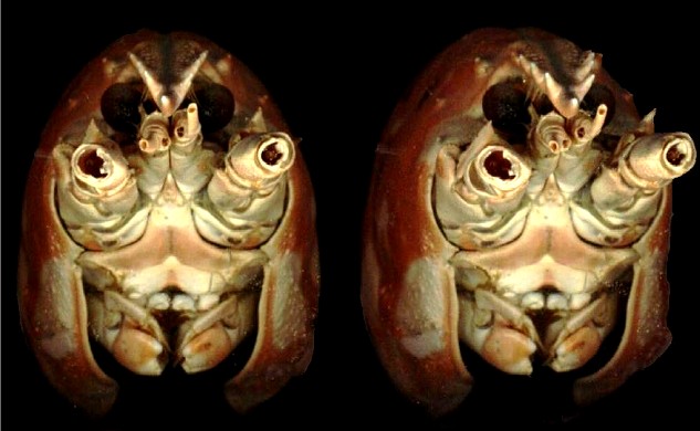
Here is a stereo photo of a lobster:

lobster.jpg

Looking at the stereo photo, you can see more details than if you were looking at the lobster.

I think you will also like the (windows exe) stereo photos at http://www.pattakon....Stereoscopy.htm (after opening the file, move the mouse around the screen to see what happens; to quit/to exit, double click on the window).

Munks, how much easier it is now for you to understand how the parts of the PatDan are assembled and cooperate?


An independent third party (Munks) confirms that "the stereo works". Believe him (not me) and try again. The gain worth the pain.

Thanks
Manolis Pattakos

#23 Kelpiecross

Kelpiecross
  • Member

  • 1,730 posts
  • Joined: October 10

Posted 29 March 2014 - 04:11


Sadly I don't think I can do it - despite much trying. When I do the cover-the-eyes trick my brain insists on seeing only the image from the right eye. Even when I have three images from two eyes (with the combined one in the middle) I think the middle one is mostly the right one - a consequence of being "right-eyed" I imagine.

You could go blind doing this - people have been warning me for years that I will go blind (I don't know why they say this).

#24 manolis

manolis
  • Member

  • 935 posts
  • Joined: May 03

Posted 30 March 2014 - 08:33

Sadly I don't think I can do it - despite much trying. When I do the cover-the-eyes trick my brain insists on seeing only the image from the right eye. Even when I have three images from two eyes (with the combined one in the middle) I think the middle one is mostly the right one - a consequence of being "right-eyed" I imagine.
You could go blind doing this - people have been warning me for years that I will go blind (I don't know why they say this).


Hello Kelpiecross.

I would propose to keep almost closed the "good" eye (in order to darken substantially the image the brain receives from this eye) so that to force your brain to use the image from the other eye, too.
If you achieve, try this http://www.pattakon....lobster_big.jpg

Thanks
Manolis Pattakos

#25 desmo

desmo
  • Tech Forum Host

  • 29,520 posts
  • Joined: January 00

Posted 30 March 2014 - 18:25

I had no problems viewing the stereo effect. I just sort of cross my eyes a bit until I see three distinct images--the center one is stereoscopic.

#26 gruntguru

gruntguru
  • Member

  • 7,642 posts
  • Joined: January 09

Posted 30 March 2014 - 23:06

Yes - brilliant. I was originally making the same mistake as KC - trying to see the right image with the right eye etc.


#27 Kelpiecross

Kelpiecross
  • Member

  • 1,730 posts
  • Joined: October 10

Posted 31 March 2014 - 09:50


The age of miracles is apparently not over - I can do it now - and quite remarkable it is too. That lobster is an ugly bastard - 3D didn't improve his looks any.

My problem was looking through the images at infinity (as you do with the "random dots" type of 3D image) - even though the brain will combine the images like this - it is not the right type of combination. The eyes need to be slightly crossed (as Desmo pointed out).
The best method for me seems to be is to look at the two images, hold a finger fairly close to your nose (about two inches for me) then look at the third (apparent) image - it resolves itself into a very clear 3D image.

For all those who think this is all a bit childish (and there probably are quite a few) as Manny says you really should make an effort to make this work.

This could be a very practical idea for displaying very complex mechanical gadgets.

Even though I had never heard of this type of "bare-eyed" 3D it seems to be well-known - thousands of images on the internet.

#28 munks

munks
  • Member

  • 428 posts
  • Joined: January 03

Posted 31 March 2014 - 17:25

Yes, I could see the PatDan CV mechanism better with this technique. For whatever reason, those other images are easier for me to hold than the lobster. Perhaps it's the ugliness that makes my eyes want to unfocus, or maybe the range of depth is larger?


#29 MatsNorway

MatsNorway
  • Member

  • 2,822 posts
  • Joined: December 09

Posted 01 April 2014 - 08:30

I put it together once. But it would not move when i made the center pieces one solid as they appeared. I might be issues related to the other constrains so i suggest putting flat surfaces on the other fork too. (i am assuming i cant just take the other one and turn it)


#30 manolis

manolis
  • Member

  • 935 posts
  • Joined: May 03

Posted 03 April 2014 - 05:26

Hello MatsNorway.

I emailed the drawing of the PatDan wherein the center triad of yokes is designed in more details.


Hello Munks

According my experience, you will soon be familiar and you will easily see the lobster, too.


Hello Kelpiecross.

Do you know the game wherein two similar pictures have a few small differences that must be found? By putting side by side the two images, in a couple of seconds you can find all the differences (they appear to the eyes/brain as "mistakes").

You write: "This could be a very practical idea for displaying very complex mechanical gadgets."
Imagine how much easier is to present a function of two independent variables (for instance the spark advance vs the engine revs and the engine load, or the injection duration vs, the engine revs and the engine load).

An advantage of this method is that the distance of the two images (and so the horizontal size of each image) can be as big as you like (much bigger than the distance of the eyes).

Another advantage in comparison to the methods wherein glasses are used (as in the 3D-TV) is that the colours stay perfect and the brightness is not affected.


Thanks
Manolis Pattakos

#31 Kelpiecross

Kelpiecross
  • Member

  • 1,730 posts
  • Joined: October 10

Posted 03 April 2014 - 11:48

The Oracle (my older brother) tells me that "cross-eyed 3D" is a recognised method for exercising the eye muscles - helping to stave off the need for reading glasses etc. as you get older.

I thought I would go blind from eye strain but remarkably my vision has improved noticeably especially over the six to ten foot range with my reading glasses off (and I don't think I am kidding myself).

Edited by Kelpiecross, 03 April 2014 - 11:57.


#32 manolis

manolis
  • Member

  • 935 posts
  • Joined: May 03

Posted 15 October 2015 - 05:34

Hello.

Today the US-PTO mailed an Issue Notification according which the US9,175,731 patent is to be granted to the PatDAN CVJ.
The official issue date is: November 03, 2015.

The application number is US14/221,283.
It is a divisional application of the original US13/745,873 application for which the US8,747,236 (PatCVJ) patent has been granted (June 10, 2014).


18 months after the application for a patent (or after the first priority claimed) the Patent Office publishes all related documents.

After this 18-months period, any communication between the USPTO and the inventors/applicants (like the Issue Notification, for instance) is open to the public.


So, you’ve got nothing to lose talking for a pending patent of yours, especially after the publication of the patent application.

Thanks
Manolis Pattakos

#33 bigleagueslider

bigleagueslider
  • Member

  • 1,235 posts
  • Joined: March 11

Posted 18 October 2015 - 04:12

I don't know how you find the time and money to patent all of your ideas. But be sure to let us know if you have any success in commercializing one of your inventions.


#34 manolis

manolis
  • Member

  • 935 posts
  • Joined: May 03

Posted 18 October 2015 - 19:16

Hello BigLeagueSlider.

You write:
“I don't know how you find the time and money to patent all of your ideas.”

I don’t.
Only few of the ideas are patented.


You also write:
“But be sure to let us know if you have any success in commercializing one of your inventions.”

You have patents of your own, so you do know how the system works.


I bet that soon after the commercialization of the first pattakon project, most of the rest pattakon projects / patents will be commercialized.


This thread is about the PatDAN Constant Velocity Joint.

It is a difficult to understand mechanism.
Can you prove geometrically that it really works as I claim?

Commercialized or not, it is an idea (actually a solution of a long existing problem) that deserves to be filed / known / patented.

You claim it is complicated. Complicated relative to what?

To put it differently:
Just show me another CVJ capable of doing what the PatDAN CVJ can do.

Thanks
Manolis Pattakos

#35 Kelpiecross

Kelpiecross
  • Member

  • 1,730 posts
  • Joined: October 10

Posted 19 October 2015 - 04:12

Have you ever made a working example of the PatDan CVJ?  


#36 manolis

manolis
  • Member

  • 935 posts
  • Joined: May 03

Posted 19 October 2015 - 07:50

Hello Kelpiecross.

You write:
“Have you ever made a working example of the PatDan CVJ?”

Yes I have.

And works as expected.

But it is made with bent welded wires, so don't ask for a photo.


With a composite 3-D printer (Mark One or similar) it could be manufactured with the required precision and it could be capable for good load carrying capacity.

Is there somebody having such a 3-D printer?

Thanks
Manolis Pattakos

#37 manolis

manolis
  • Member

  • 935 posts
  • Joined: May 03

Posted 23 November 2018 - 08:09

Hello all.


Here is a demo PatDan CVJ prototype made of PLA plastic on a 3D-printer:


Thanks

Manolis Pattakos