Thanks
Manousos

Member
Posted 29 September 2009 - 15:37
How do you keep the correct cam timing with that?
I quite like the idea though otherwise.

Member
Posted 29 September 2009 - 16:10


Member
Posted 29 September 2009 - 18:33


Member
Posted 29 September 2009 - 22:48
Boy! Why don't we just stick with having the pistons go up and down?
Member
Posted 30 September 2009 - 02:56
Edited by cheapracer, 30 September 2009 - 03:01.

Member
Posted 30 September 2009 - 06:03
Member
Posted 30 September 2009 - 07:05

Edited by gruntguru, 30 September 2009 - 07:11.

Member
Posted 01 October 2009 - 04:27

Member
Posted 02 October 2009 - 03:24
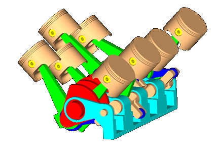
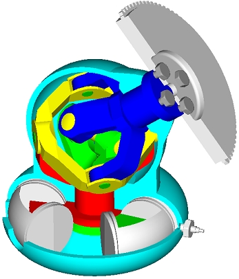
The Ehrlich system is the most promising VCR I have seen, plus it features variable displacement. Moving the pivot left and right varies the displacement. Up and down varies the CR. . . .
Edited by manolis, 02 October 2009 - 03:25.
Member
Posted 02 October 2009 - 03:29
Didn't Yamaha have a hydraulic version on their two stroke 500cc race bikes? I could not find a picture of it but I remember reading it years ago.
Member
Posted 02 October 2009 - 05:35
Member
Posted 02 October 2009 - 06:01
Member
Posted 02 October 2009 - 06:14
The benefits are considerable, especially with downsized, high boost engines. The challenge is to reduce the cost side of the ratio.Are the benefits of VCR really of enough significance to warrant the extra complexity, weight and expense of these mechanisms? Some of these systems look like they would almost double the complexity of a conventional engine, and I wonder about the cost:benefit ratio...
Member
Posted 02 October 2009 - 06:21
Are the benefits of VCR really of enough significance to warrant the extra complexity, weight and expense of these mechanisms? Some of these systems look like they would almost double the complexity of a conventional engine, and I wonder about the cost:benefit ratio...
Edited by manolis, 02 October 2009 - 06:22.
Member
Posted 02 October 2009 - 06:40
So the CR will be basically linked to MAP to give better performance at no/low boost, and allow higher maximum boost pressures to be used?The benefits are considerable, especially with downsized, high boost engines. The challenge is to reduce the cost side of the ratio.
Member
Posted 02 October 2009 - 08:17
Yes. The main shortcoming of turbo downsized engines for production cars is the poor part-throttle/off-boost economy of the low compression engine.So the CR will be basically linked to MAP to give better performance at no/low boost, and allow higher maximum boost pressures to be used?
Member
Posted 02 October 2009 - 08:59
Advertisement
Member
Posted 02 October 2009 - 09:25
Not quite, because pumping and friction losses at part throttle still reduce efficiency significantly, but VCR does help a lot. The high boost downsize engine fares better (than the NA) in this regard since its pumping and friction losses are lower.Alternative to the hybrid technology is the Variable Compression Ratio (VCR) for both naturally aspirating and turbocharged engines.
At partial loads the VCR increases the compression ratio as much as possible (just before knocking) making the engine as efficient as if it were working in heavy load.
Member
Posted 02 October 2009 - 10:08
Not quite, because pumping and friction losses at part throttle still reduce efficiency significantly, but VCR does help a lot. The high boost downsize engine fares better (than the NA) in this regard since its pumping and friction losses are lower.
Member
Posted 02 October 2009 - 10:22
Agree on the VVA. My point on the high boost downsized engine is it has a greater dynamic range -> greater range of cylinder filling -> wider range of TDC cylinder pressure (without VCR) -> greater benefit from VCR.There is the Desmodromic VVA (or DVVA) to minimize the punmping and friction losses ( read at Desmodromic Fully Variable VVA for more). The DVVA controls independently the valve duration and the valve lift, is rid of valve springs and other restroing springs.
The high boost downsized engines do take advantages from a VCR, but this is also true for the naturally aspirating engines.
In town traffic, a big conventional naturally aspirating V8 is more like a CO2 generator than a mechanical energy generator. This can change by a good VCR. A good VVA in the cylinder head can improve things further.

Member
Posted 05 October 2009 - 17:05
Member
Posted 05 October 2009 - 17:11
Member
Posted 05 October 2009 - 17:28
The number of patents and patents applications of Nissan, Honda, Mercedes etc for their multilink VCR says a lot.
Member
Posted 05 October 2009 - 23:13
Actually some of the multi-rod-crank mechanisms (including the Ehrlich system I mentioned in a previous post) are capable of variable displacement and VCR, so therefore should be capable of VCR with constant clearance volume.By the way, the above concept with an eccentric crank journal is exactly new... Gomecsys (working with ProDrive) has a similar approach to yours, since both vary the eccentricity at the con rod big-end. In the scheme of generic VCR concepts (your own picture below again), it falls closest to "2-C". However, almost ALL of the illustrated concepts except "E" suffer from the same fundamental problem I've explained in my previous post above of changing the TDC piston position and altering the quench clearance.
Member
Posted 06 October 2009 - 07:45
Let's suppose we built your ideal VCR system, having constant Vclearance (some call it dead volume) and variable Compression Ratio (CR).You asked for comments, I'll bite. Every incarnation of VCR mechanisms adjust the compression ratio by changing the clearance volume,
where CR = (Vclearance + Vswept) / Vclearance
In the overwhelming majority of VCR incarnations, including the all the ones illustrated above, the change in compression ratio is achieved by altering the clearance volume via adjusting relative piston position at crank TDC. . . .
Otherwise, there is still significant resistance of the added cost/complexity/fuel consumption benefit trade-off preventing widespread OEM deployment of VCR in series production.
Altering the effective compression ratio by valve timing (e.g. Miller/Atkinson cycle) gives most of the benefits of VCR and is robust, proven, cost-effective technology.
Member
Posted 06 October 2009 - 07:58
By the way, the above concept with an eccentric crank journal is exactly new... Gomecsys (working with ProDrive) has a similar approach to yours, since both vary the eccentricity at the con rod big-end. In the scheme of generic VCR concepts (your own picture below again), it falls closest to "2-C". However, almost ALL of the illustrated concepts except "E" suffer from the same fundamental problem I've explained in my previous post above of changing the TDC piston position and altering the quench clearance.
. . .
t the TDC remains shielded in secret development labs... Would you be so kind to give credit where it's due when it comes to the light of day.
FEV also has a Type "3-C" concept, although I'm aware that they have EVERY main type covered in various concepts:
http://www.fev.com/c...ult.aspx?id=498
Member
Posted 06 October 2009 - 11:13
FEV's VCR, with all its problems, was installed and succesfully tested in a VW, confirming the potential of the VCR technology.
Member
Posted 06 October 2009 - 16:32
Edited by TDIMeister, 06 October 2009 - 16:34.
Member
Posted 06 October 2009 - 17:54
Manousos, there is a small flaw in logic. There is absolutely no need to have a range of geometric CR adjustment from 7:1 to 19:1. SI engines attain peak fuel conversion efficiency at compression ratios between 14-16:1. Furthermore, with gasoline direct injection and variable valve timing (cam phaser in the simplest form), you can run obtain >20 bar BMEP in a forced-induction engine with minimal full-load mixture enrichment at compression ratios approaching 10:1. I know because I've done it. I take for granted that any future engines that might incorporate VCR will also incorporate GDI and VVT.
In reality, you only need a range of adjustment between 9.5-14:1 for a forced-induction SI engine to cover the optimum range of BSFC over a wide load and speed range, and maybe 11-14.5:1 for a naturally-aspirated engine, the respective lower limits being for knock control. And when one performs detailed simulation (validated with testing) and cost analyses, the implementation-cost-to-fuel-consumption-benefit ratio still trails behind other solutions (e.g., variable valve timing, cylinder deactivation, downsizing, full-load cooled EGR), etc.
Member
Posted 06 October 2009 - 21:45
To sacrifice everything for the sake of the "optimized combustion chamber" is not reasonable.
Even for the 9.5:1 to 14:1 compression ratio range you mention (which is narrow), an engine having at light load 2600cc capacity (compression ratio 14:1, constant dead volume) operates as a poor 1700cc engine at heavy load / high revs (compression ratio 9.5:1). I.e. your ideal VCR does exactly the opposite it has to do: at peak power it decreases the engine capacity. It is also the balancing issue (vibrations), etc, etc.
The analysis explains what I know and you know: such an approach is not good, not even theoretically.
And the analysis was based on the assumption that you can realize your ideal VCR by a compact, light, reliable and efficient mechanism.
In practice there is no mechanism capable to keep the TDC "constant" and to displace the BDC, keeping at the same time the rest characteristics of the piston motion and of the engine acceptably good (unless you have one).
I propose to get back to the patcrank VCR which is based on a compact, light, reliable and efficient mechanism.
In any case thank you because your reply was the only - until now - "strictly technical".
PS.
They locked me out of Eng-Tips forum and deleted my posts there.
I know you are in.
If you please, write to "JCReynolds79" (thread "Wankel Rotary Engine Geometry") that a program that generates the Wankel rotor "envelope" is prepared and is at http://www.pattakon....man/WANKELN.exe and the code at http://www.pattakon....man/WANKELN.txt If he has any questions, he can e-mail me at vva@pattakon.com .
Manousos
Member
Posted 07 October 2009 - 03:16
9.5:1 to 14:1 is not a narrow compression ratio range. Friction and heat losses increase with the compression ratio, so there is no benefit with very high compression ratios. Saabs SVC engine made use of a 8:1 to 14:1 ratio range, but that was also a port injected engine which adjusted the TDC volume by tilting the cylinders. That engine was functional, the test cars were even driven by journalists (the picture I posted above) and they had a patent on it. But in the end GM stopped the development for cost reasons. There are in other words, as explained by TDIMeister, cheaper ways to improve the fuel consumption. To be competitive you need to spend the money where it gives the biggest return in the form of lower fuel costs.
Edited by manolis, 07 October 2009 - 05:03.
Member
Posted 07 October 2009 - 05:23
It spoils the shape of the combustion chamber for some compression ratios (the combustion chamber becomes narrow at one side and wide at the opposite side of the cylinder).
Member
Posted 07 October 2009 - 06:16
You are right.Whaaaat!! Who wrote this nonsense! The cylinder bores tilt along with the head.
Member
Posted 07 November 2009 - 08:18
Member
Posted 07 November 2009 - 19:04
No.
When the engine operates at light load, let say 1/4 (common situation in urban cycle) the in-cylinder pressure and temp is low.
What the patcrank VCR does?
It simply displaces the piston stroke a little (let say 4mm) closer to the cylinder head to reduce the dead volume.
At these last 4mm of the stroke is where the cycle differs than the cycle without VCR.
You do spend a little more energy to compress the mixture at the last 4mm, but the mixture now burns as if it were in the engine running at heavy load: the flame propagation is fast and the pressure rises to values comparable to the pressures met at heavy load operation.
A greater part of fuel's thermal energy changes into mechanical energy, that means lower consumption, less emissions etc.
This is because the expansion of the mixture - after TDC - returns much more energy than the additional energy spend during the last 4mm of compression.
Member
Posted 08 November 2009 - 04:02
As you know J, torque reduction without throttling is also being achieved using direct injection. By producing a stratified charge the fuelling and therefore the torque can be reduced by up to 50% (maybe more in future?) without throttling.You won't get burns similar to high load by increasing the compression ratio, and increasing the compression ratio WILL increase heat and friction losses and when those losses are greater than the gain seen due to the increase in compression ratio, there is no point to increase the compression ratio further.
There is also simpler and better methods to get around the low load operation you mention. Displacement on demand is one, the other is downsizing and turbocharging. It's also possible to handle low load operation using the Miller cycle with late or early intake valve closing. Can you control the intake valve lift profile it's also possible to get rid of the throttle as the engine torque can be controled by valve timing instead.
Edited by gruntguru, 08 November 2009 - 04:03.
Member
Posted 08 November 2009 - 05:09
You won't get burns similar to high load by increasing the compression ratio . . . timing instead.
Advertisement
Member
Posted 18 November 2009 - 12:53

Member
Posted 18 November 2009 - 16:59
Better fuel?On the same reasoning, the increase of the compression ratio of an engine from 6:1 (typical value many years ago) to 12:1 “WILL increase heat and friction losses”; yet the fuel consumption of a modern engine having 12:1 compression ratio, is way lower.
Member
Posted 19 November 2009 - 02:01
Member
Posted 19 November 2009 - 06:51
The pumping loss is the energy per cycle the engine pays to suction the next charge. With the correct valve lift profile (i.e. valve lift, valve duration, valve timing) the pumping loss can be significantly reduced at partial loads. This is one of the things a good VVA (Variable Valve Actuation) system does.Primarily real benefits to variable compression would be complements from variable cam. At really low to medium engine operation, throttle, detonation would be far away so compression ratio can be pushed very high to obtain good fuel economy. It should be relative to how much air to compression ratio goes. At low to medium throttle, i think in most cases the combustion chamber pressure is pretty much negative at bottom dead center to probably even 90 degree towards TDC so pumping friction should not be so critical.
The higher . . . they call it HCCI and the core to this is both, to obtain high compression for efficient burning and claiming homogeneous charge offer a high charge for the same volume although they found that the petrol charge is too unpredictable resulting in the need for a variable compression ratio method to control the point of combustion.
Member
Posted 07 February 2010 - 10:46


© MOTORSPORT NETWORK 2024. All rights reserved. Community Forum Software by IP.Board

