In the US a couple of weeks ago I had a chance to examine the innards of the Collier Collection's 1913-14 3-litre (183 cubic inch) Peugeot. The engine is currently completely stripped to the last nut and bolt and its fabric bears evidence of a possibly revealing background to the cars' story.
This engine was last rebuilt - we think - for Briggs Cunningham when the Peugeot was part of his Collection, pre-Collier.
Phil Reilly's people have pulled it down and it reveals some curious anomalies.
Every single con-rod had a different offset upon its big-end. In other words every big end bearing was not precisely centred under the centreline of the con-rod itself, but instead each was offset somewhat to one side or the other.
There seemed no rhyme nor reason for this, until the block casting - undoubtedly the original, it would seem - was precisely measured.
Then it was discovered that there was no consistency between the centreline of each cylinder bore. Nobody in his right mind would design an in-line 4-cylinder engine in such a way so how the ------....??????
One theory came up in the minds of Phil's specialists - perhaps the pattern cores had shifted while the cylinder block was being cast?
Now this made sense, because we know that these works team cars for the 1913 Coupe de l'Auto were built very quickly, to an extremely tight schedule.
Castings such as cylinder blocks and crankcases are long lead items, and they would be put in train long before relatively easily forged and machined components.
Now just imagine that terrible Tuesday morning in the experimental department at Peugeot when the long awaited block castings were delivered, and passed through inspection.
"Aaah! Merde! Sacre bleu..." etc - the cores have shifted!
What could be done? Well perhaps - just perhaps, considering the surviving evidence of the block and rods today - some bright spark then knuckled his forehead and said "Eureka! J'ai un idee!" - and he came up with the notion to use the miscast blocks regardless (because there was insufficient time left to have them satisfactorily re-cast), and simply to accommodate the dimensional vagaries by independently offsetting each con-rod big-end to compensate.
Hmm - possible - but it's certainly a scenario which, perhaps, has that ring of believability about it...a glimpse of a past truth perhaps, brought down to us in the surviving metal.
DCN

Indy Peugeot story...
Started by
Doug Nye
, Aug 28 2004 21:40
33 replies to this topic
Advertisement
#2

MPea3
-

- 2,177 posts
- Joined: July 01
Member
Posted 28 August 2004 - 22:19
This is a different model car and engine from the 1913 Peugeots Eddie Rickenbacker and Bob Burman drove (and broke conrods in) in 1914-15? I thought they were somewhere over 5 liters, as reducing the Peugeot engine to 5 liters was part of what Burman hired Miller to do.
Also, is this the engine which was at least partly dismantled and drawn by Jim Toensing while it was at Cunninghams?
Also, is this the engine which was at least partly dismantled and drawn by Jim Toensing while it was at Cunninghams?
#3
Hans Etzrodt
-

- 3,188 posts
- Joined: July 00
Member
Posted 28 August 2004 - 22:37
So, that meant they had to rework their crankshaft-rod-ends or make entirely new modified crankshafts?Originally posted by Doug Nye
...Now just imagine that terrible Tuesday morning in the experimental department at Peugeot when the long awaited block castings were delivered, and passed through inspection.
"Aaah! Merde! Sacre bleu..." etc - the cores have shifted!...

#4
GIGLEUX
-

- 1,519 posts
- Joined: April 03
Member
Posted 28 August 2004 - 22:47
"Merde, Sacre bleu"
Doug, your knowledge of french is increasing consistantly! but better to write "sacrebleu".
Apart that, fascinating info. I read somewhere, but where?, that with pre-WW1 cars cylinders were not always strictly on the same line.
#5
Doug Nye
-
- 11,535 posts
- Joined: February 02
Member
Posted 28 August 2004 - 23:11
Originally posted by Hans Etzrodt
So, that meant they had to rework their crankshaft-rod-ends or make entirely new modified crankshafts?
No Hans - the Peugeot crankshaft is in two halves in order to accept a roller bearing at its middle. Each rod big-end sat happily on the crank - it's just that the shank axis of each con-rod is offset longitudinally - i.e. as in side elevation view - from its integral big-end section - and each one of the four is actually offset by a differing amount.
Yes, by the way MPea3, this is the engine which was drawn by Jim Toensing - and the valvegear drawings - and the drawings of the piece in the Pomeroy 'Grand Prix Car' book - have both got the valvegear wrong. It doesn't work satisfactorily as drawn by Jim and as reworked probably during the Cunningham rebuild - if not before?
J-MG - thanks for the correction - I think the offset you are thinking of was in the lateral-section sense, crankshaft centreline versus cylinder bore centreline - while what I am speaking of is in the longitudinal, side-elevation sense, varying measurements from one cylinder bore centre to the next in line, then to the next after that... I'll post some photos when they come through to me.
Incidentally - the Peugeot engine mounting system is fascinating. The legendary 4-valves per cylinder/hemispherical combustion chamber engine does not bolt - conventionally - via cast-on legs or lugs directly into the forepart of the chassis frame.
Instead it bolts into a separate and lengthy U-shaped sub-frame member which is pivoted up front on the curve of the U onto the chassis' front cross-member, via a kind of gimbal bearing. The rear extremity of each leg of this U - which extends rearwards within the space between the chassis side-frames - is then attached to those main rails on each side via another gimbal bearing.
This must have freed the crankcase casting from torsional stresses within the frame. The front end of the chassis frame itself, meanwhile, is stiffened at each front corner by heftily dimensioned thick steel triangular plates rigidly attached.
There's a whole lot more to these ingenious cars than perhaps one finds in the cold print of most of our history books.
DCN
#6
MPea3
-
- 2,177 posts
- Joined: July 01
Member
Posted 29 August 2004 - 00:41
Originally posted by Doug Nye
Incidentally - the Peugeot engine mounting system is fascinating. The legendary 4-valves per cylinder/hemispherical combustion chamber engine does not bolt - conventionally - via cast-on legs or lugs directly into the forepart of the chassis frame.
Instead it bolts into a separate and lengthy U-shaped sub-frame member which is pivoted up front on the curve of the U onto the chassis' front cross-member, via a kind of gimbal bearing. The rear extremity of each leg of this U - which extends rearwards within the space between the chassis side-frames - is then attached to those main rails on each side via another gimbal bearing.
This must have freed the crankcase casting from torsional stresses within the frame. The front end of the chassis frame itself, meanwhile, is stiffened at each front corner by heftily dimensioned thick steel triangular plates rigidly attached.
DCN
This sounds similar in concept (if not executed the same) to how Offy's were mounted into rail frame cars. Something else that maybe Miller and his gang took from the Peugeot? The Miller marine engines used a more conventional engine mounting arrangement while the car engines used a 3 point mount.
Also, is the crankcase cast iron?
As far as the Toensing drawings, the Gordon Eliot White book on Offenhauser shows drawings of the Peugeot valve train as it was guessed to be, as well as the Toensing drawing, which is stated to have been done after disassembly of the engine. Is the engien in it's current form different now, and if so, was it modified while at Cunningham's?
Also, this word "merde"... being a Yank, I speak no language well, but doesn't that stand for "Motor Racing Development"?

#7
Mike Argetsinger
-

- 948 posts
- Joined: April 00
Member
Posted 29 August 2004 - 05:35
A great thread and one to which I can contribute nothing. But perhaps I will be forgiven an observation that comes to mind while thinking about this 1914 Peugeot.
Briggs Cunningham also owned a 1914 Mercedes Grand Prix car. He brought this out to the vintage race at Bridgehampton in 1959. It was the oldest car in the race and he drove it to a second place finish, beaten only by Dan Donohue in a Type 44 Bugatti. The field included Austin Clark in a 1923 Mercedes, New Yorker cartoonist Charles Addams in a 1932 Alfa Romeo, Dave Garroway of the NBC Today show, in his 1937 Jaguar SS, and others.
What fascinates me - and made me do my math twice before I believed it - is that the Mercedes was 45-years old that day. And now an additional 45-years have passed.
#8
Hans Etzrodt
-
- 3,188 posts
- Joined: July 00
Member
Posted 29 August 2004 - 06:23
Doug - do I understand you correctly when I say that the shank axis of each con-rod was offset longitudinally to achieve the same stroke for each rod/piston in that faulty block?Originally posted by Doug Nye
...the Peugeot crankshaft is in two halves in order to accept a roller bearing at its middle. Each rod big-end sat happily on the crank - it's just that the shank axis of each con-rod is offset longitudinally - i.e. as in side elevation view - from its integral big-end section - and each one of the four is actually offset by a differing amount...
#9
dbw
-

- 993 posts
- Joined: October 00
Member
Posted 29 August 2004 - 07:43
interesting story.....i know phil's gang and highly respect their inputs...the important thing to note however ,does the offset on the big ends match the bore misalignment for each cylinder?..are the rods numbered and faced the correct direction?..i wonder how the bore mis-alignment affected the valve and cam placement...i have to assume the valve stems had to remain in close linear tolerence for the cam to work properly.....some other things to consider;while peugeot was building quality cars in great numbers, i'm sure the race engines were built off-line and literally by hand...with an irregular casting,the fixturing alone is a nightmare to bore blindly from the cylinder skirt up to the top of the combustion chamber.. ask anyone who's attempted to bore and hone a bugatti t-51 block [and they were surfaced on all sides to facilitate ease of alignment..]..i'm sure the core-shift theory has merit but has anyone given the block an MRI to check how the bores center on the waterjackets?....has it ever been overbored?..i can just see ross scratching his head..this is the kind of stuff that drives him crazy!
i just reread the second of dcn's post...if i understand the logitudinal dimensions between bore centerlines differ then i wonder if the camlobes are ground to match or does the lobe to stem action allow for a bit of misalignment?...if the valves remain in proper situation with the bore it would show with the cambox removed....do the sparkplug-to sparkplug dimensions differ?? i guess i'm asking if each bore was machined as an individual unit [bore/valves/sparkplug]or was the bore machined a bit off with all the other stuff in spec..a bit difficult with a monobloc i would assume...
just wondering
#10
fines
-

- 9,647 posts
- Joined: September 00
Member
Posted 29 August 2004 - 09:46
Very interesting! dbw, I suspect the camshafts, lobes, valve and sparkplug seats etc. would've been modified to fit properly over the bore, unless the offset would've been so minimal as to not interfere with the lobe-to-stem action - actually, I'm hard pressed to believe these would tolerate much of an offset!
Also, I don't think I have ever heard of this engine mounting device. But MPea3, from memory, weren't all Miller and Offenhauser engine mounts of the yoke type??? Actually, I'm pretty sure they were, at least I don't recall a similar system to this one!
Also, I don't think I have ever heard of this engine mounting device. But MPea3, from memory, weren't all Miller and Offenhauser engine mounts of the yoke type??? Actually, I'm pretty sure they were, at least I don't recall a similar system to this one!
#11
fines
-
- 9,647 posts
- Joined: September 00
Member
Posted 29 August 2004 - 09:51
Ah yes, and Doug I'm intrigued you're saying that both drawings of the valve gear are wrong! So now, can you draw us a correct version? 
#12
MPea3
-
- 2,177 posts
- Joined: July 01
Member
Posted 29 August 2004 - 11:11
Originally posted by fines
Very interesting! dbw, I suspect the camshafts, lobes, valve and sparkplug seats etc. would've been modified to fit properly over the bore, unless the offset would've been so minimal as to not interfere with the lobe-to-stem action - actually, I'm hard pressed to believe these would tolerate much of an offset!
Also, I don't think I have ever heard of this engine mounting device. But MPea3, from memory, weren't all Miller and Offenhauser engine mounts of the yoke type??? Actually, I'm pretty sure they were, at least I don't recall a similar system to this one!
I don't see how anything of the valve train could have been modified to align over the cylinders. Obviously the camshafts can't, any more than a crank could have been. To correctly align valves over mis-aligned cylinders would require the use of some sort of rocker type of tappet and all sorts of messing around with cam profiles, would it not?
Which leads to the question, with different drawings showing different types of tappets, what type does the engine have?
As far as the engine mounts, I certainly agree that the system Doug describes for the Peugeot is unlike anything I've ever seen. My point (if poorly worded as usual) was that the central from engine mount on Millers and Offys might have been influenced by the Peugeot in order to take into account frame flex. Also, marine engines did have 2 front mount points, and the Kurtis Offy which lives near me definitely has a solid 2 point mount plate bolted to the front of the engine. In White's book he shows examples of both.
#13
fines
-
- 9,647 posts
- Joined: September 00
Member
Posted 29 August 2004 - 11:28
Aren't we speaking of longitudinal offset of the cylinders? In which case, as dbw pointed out, the camlobes could have been offset as well - I'm no expert in machining, but I don't see any fundamental problems with that!
Point taken re engine mounting, i.e. the idea of relieving the block of flexing forces may have come from the Peugeot. Must take another look at the Offy book, since I can't recall the 2-point mounting you described.
Point taken re engine mounting, i.e. the idea of relieving the block of flexing forces may have come from the Peugeot. Must take another look at the Offy book, since I can't recall the 2-point mounting you described.
#14
MPea3
-
- 2,177 posts
- Joined: July 01
Member
Posted 29 August 2004 - 11:40
Originally posted by fines
Aren't we speaking of longitudinal offset of the cylinders?
I don't know, but my best guess is that if cores shifted, it might not be just longitudianlly...
#16
Arturo Pereira
-

- 843 posts
- Joined: March 01
Member
Posted 29 August 2004 - 13:58
Fascinating story for sure, and a mistery to be solved. Work of Les Charlatans maybe ??;)
#17
Doug Nye
-
- 11,535 posts
- Joined: February 02
Member
Posted 29 August 2004 - 15:27
Any substantial core shift - if core shift it was - was certainly most marked in the longitudinal sense. Rest of the assembly all seems to have been tailor-made to line-up...and this is ONLY a theory for what happened but definitely the basic casting lacks the dimensional consistency one might expect and the con-rod shank offsets relative to their big-end sections genuinely all differ.
One other question is the use of substantial H-section rods within this engine, since there's some question of an early Indy photograph being recalled which shows someone holding aloft a tubular 'Peugeot rod' and ring-testing it.
The question here would be might the Premier rods for the Peugeot copies have adopted an alternative form - and if so then which did Peugeot originally use - H or tubular...????
Evidence, anybody?
DCN
#18
fines
-
- 9,647 posts
- Joined: September 00
Member
Posted 29 August 2004 - 15:42
Doug, as far as I know the Peugeots all used H-section rods, but replacement rods by Miller would be tubular. Don't know about the Premier ottomh, though.
#19
robert dick
-

- 1,300 posts
- Joined: October 02
Member
Posted 29 August 2004 - 16:08
The centre-line of the rod is offset in relation to the centre-line of the crankpin: This was typical for Ernest Henry, beginning in 1913 with the 5.6- and 3-litre Peugeots, and still used on the 1919 and 1920 Ballots, the 4.9- and 3-litre straight-eights. It was a consequense of the two-piece crankshafts in the four-cylinder Peugeots and of the four-piece crankshafts in the Ballots, running in ball- or roller bearings (Pomeroy wrote: ... it has since been shown that the extra overhang area obtained by offsetting is virtually useless...).
But of course the original idea was to offset each of the cylinders by the same dimension.
Normally the Peugeot blocks were manufactured by Mégevet, in a small factory at Bellegarde, a few kilometres from Geneva, in France. Mégevet was a serious company so that an "asymmetric" block is really improbable. There was enough time to deliver correct material.
Has the block of the ex-Cunningham Peugeot been rebored? Is it the original block?
According to descriptions in the contemporary press, the crankshafts of the 1913/14 Peugeots ran in three ball bearings
(... the Peugeot crankshaft is in two halves in order to accept a roller bearing at its middle...). A sectional drawing of the WWI Vee-eight Peugeot aero-engine (DOHC four-valve head) shows ball bearings.
Are there roller bearings in the ex-Cunningham Peugeot?
Concerning the Ballots, there are different descriptions, some of them mentioning five ball bearings, others five roller bearings or three ball (ends + middle) and two roller bearings.
As far as I know this ex-Cunningham Peugeot was originally sold by the factory team to the Menier family (of sugar/chocolate fame), driven by Arthur Duray in the 1914 Indianapolis 500, sold to Stutz, and then driven by George Babcock in the 1915 Indianapolis 500. Already in 1915 it was an old warrior. Maybe the block was replaced.
= = = = = =
Tubular connecting rods:
The Burman special, the ex-factory 1914 Indianapolis 5.6-litre rebuilt in the Miller shops, had tubular rods.
Advertisement
#20
Arthur Anderson
-

- 151 posts
- Joined: June 04
Member
Posted 29 August 2004 - 16:55
I would be willing to bet that the "offset" found in the Peugeot engine was not at all uncommon, almost no matter the skills of the machinists of the day. This is certainly not to "knock" the men who conceived and designed this engine, nor any of the people who worked in its original construction.
Even as late as 1913, the concept of absolute precision of engine manufacture (so soundly preached by none other than Henry Leland, founder of Cadillac) hadn't really reached into all corners of the industry--even the most vaunted of cars all over still relied, often, on the individual fitting of parts, due to variations in dimensions. For example, even as late as 1969, mass-production high-output V8's were notorious for mis-matched cylinder bores. I witnessed a very experienced engine-builder here locally having to have the cylinder bores of a 440cid Dodge V8 correctly aligned (none of the cylinders were exactly perpendicular aligned to the centerline of the crankshaft, and while none were out all that much, no two cylinders had the same centerline either!). As a further example, even the mighty Duesenberg Model J straight eight engines had to have their rods individually fitted to the crankshaft due to slight variations between the cylinders, again the result of a very small production run of that engine, only about 500 were produced by Lycoming, themselves an engine producer of no small repute, then, or today.
As the Peugeot racing engines were created in what must have been an "experimental" situation, it's doubtful that absolute precision was then possible, or perhaps even a serious consideration. Given the early state of machine tools then, as compared to today, it might not have been even possible in a 'back shop" situation. With the relatively low rpm range of even racing engines then, it's likely that such seeming imprecise spacing of cylinders (and subsequently the spacing of connecting rods on their respective jounals) really wasn't a serious consideration, as long as there was no serious "out of balance", although it certainly would have made sense to have at least statically balanced all moving components (crank, rods, pistons) as that was certainly known and practiced then, even with the lowly Model T Ford, to at least some degree of fine tolerance.
Even the art of sand-casting foundry work wasn't nearly the precise thing it became over the next decade or so--and sand-casting iron or steel still isn't, hence the need to machine the finished casting.
Just a thought.
Art
#21
Arthur Anderson
-
- 151 posts
- Joined: June 04
Member
Posted 29 August 2004 - 17:16
Originally posted by robert dick
The centre-line of the rod is offset in relation to the centre-line of the crankpin: This was typical for Ernest Henry, beginning in 1913 with the 5.6- and 3-litre Peugeots, and still used on the 1919 and 1920 Ballots, the 4.9- and 3-litre straight-eights. It was a consequense of the two-piece crankshafts in the four-cylinder Peugeots and of the four-piece crankshafts in the Ballots, running in ball- or roller bearings (Pomeroy wrote: ... it has since been shown that the extra overhang area obtained by offsetting is virtually useless...).
But of course the original idea was to offset each of the cylinders by the same dimension.
Normally the Peugeot blocks were manufactured by Mégevet, in a small factory at Bellegarde, a few kilometres from Geneva, in France. Mégevet was a serious company so that an "asymmetric" block is really improbable. There was enough time to deliver correct material.
Has the block of the ex-Cunningham Peugeot been rebored? Is it the original block?
The practice of offsetting the cylinder centerline in relation to the centerline of the crankshaft itself was very common with early inline engines, the centerline of the cylinder bore being offset in the direction of rotation (many production engines, well into the 1930's have the cylinder bore offset as much as a half-inch in the direction of rotation!), which increased the torque, as engineers understood it back then, without having to try to get higher rpm's than the rather primitive (by today's standards) bearings, and the long stroke of the engine.
Given the "assembled" nature of the Peugeot engine (and in the teen's, many inline engines were still built with crankcase separate from the cylinder blocks), it seems only plausible that there was great difficulty in ensuring the precise alignment of cylinder bore with the crankshaft, especially when one considers the dissimilar metal used (iron block, aluminum crankcase), and even more difficult with the then-unique "barrel crankcase" as pioneered by Peugeot, and then carried on into the Miller-Offenhauser-Meyer Drake era's.
It must have been interesting to have seen how that engine was developed, and to have witnessed the discussions, perhaps even passionate arguments amongst the people involved--I'd be willing to bet there were several times when the French language was stretched to the limit of invectives (as any language would have been in similar circumstances). Oh, to have been a fly, on the wall of that shop!
Art
#22
dbw
-
- 993 posts
- Joined: October 00
Member
Posted 29 August 2004 - 17:31
tho it's apples and oranges...miller typically used a solid torque-plate at the crankcase rear and the single coaxial "snout" at the front...indeed to isolate the torque of the parallel frame rails from the crankcase...incidentally ford did had a similar approach that served the ford T faithfully from 1909 to 1927.
the odd thing tho [not surprising] is how messr bugatti, faced with a pair of equally whippy rails, just went ahead and put four rigid feet on each corner of the alloy[!] crankcase from the type 10 right up thru the grand prix cars of the '30s...the result? ..just try to find an original bug lower crankcase without an arm repair--or two!
the odd thing tho [not surprising] is how messr bugatti, faced with a pair of equally whippy rails, just went ahead and put four rigid feet on each corner of the alloy[!] crankcase from the type 10 right up thru the grand prix cars of the '30s...the result? ..just try to find an original bug lower crankcase without an arm repair--or two!
#23
Doug Nye
-
- 11,535 posts
- Joined: February 02
Member
Posted 29 August 2004 - 17:37
This is a case of offset in the longitudinal sense along the length of the engine, not laterally across the engine.
In conversation - remember we were only standing in the workshop examining the bits and pondering the dimensional peculiarities - the odd thing was that the aluminium crankcase casting itself was plainly inconsistent. There is confidence it is the original.
The crankshaft, however, is especially interesting, in two parts which unite amidships via a taper and fine screw-thread. The finish on one crankshaft half appears far superior to that of the other, and within the crankcase there are two gouge marks in the area served by the poorer-finish crankshaft half - which is the suspected replacement for a better-finished original.
When we noticed these gouge marks on the inner face of the crankcase I ran my fingers over the outside of the case and there - sure enough - were two raised dimples. It looks as if rods had been thrown and had assaulted the inside of the case hard enough to raise two stretched 'domes' without either cracking the material or breaking through it.
Yes Robert this was the Menier car which raced on in modified form for several years in America - ultimately as a special owned and run by a guy with a peculiar name which I cannot right now recall, nor have I time to consult the reference. The basic Peugeot 183CID engine seems simply to have run on, and on, though not - as described above - without experiencing a variety of dramas...and remedial attention.
DCN
#24
T54
-

- 2,504 posts
- Joined: November 03
Member
Posted 29 August 2004 - 17:39
This engine was last rebuilt - we think - for Briggs Cunningham when the Peugeot was part of his Collection, pre-Collier.
Indeed, the engine was partially rebuilt in 1975. I remember seeing the whole mess in the restoration shop with both John Burgess and Jim Toensing looking it over. From the comments I remember, the engine had been previously rebuilt first in the early 1920's then in the late 1940's using available Premier and other hand-machined parts. They were stunned at the weird individual fitting, which they compared to "an old hand-made, pre-civil war rifle".
Later, I got involved in helping them to find the barrel-shaped roller bearings for the 1927 8-cylinder Delage GP, and we discovered that SKF was still using some of identical dimensions in steel caged bearings. We got SKF to donate enough of the bearings to fit the 200-plus rollers, and we had to destroy the cages to get to the actual rollers, then re-fit them in the aluminum half cages. All the original rollers were made into lapel pins with a certificate and a number for each. I still have mine somewhere...
Boy, I LOVED that place.
Regards,
T54
#25
VAR1016
-

- 2,826 posts
- Joined: June 02
Member
Posted 29 August 2004 - 18:11
I don't understand this at all.
If the cylinders were in the "wrong" place, why didn't Peugeot simply line them? Surely that would have been easier and probably much quicker, than making off set con-rods?
PdeRL
If the cylinders were in the "wrong" place, why didn't Peugeot simply line them? Surely that would have been easier and probably much quicker, than making off set con-rods?
PdeRL
#26
xkssFrankOpalka
-

- 242 posts
- Joined: March 04
Member
Posted 30 August 2004 - 02:10
I have my Delage pin also but didnt know the story, thanks, wish I had the Certificate to go with it, I guess Blueprinting engines didnt start until much later.
#27
Ray Bell
-

- 80,260 posts
- Joined: December 99
Member
Posted 31 August 2004 - 21:40
On the contrary, I would say this is an extreme case of blueprinting...
Working with dimensions that simply didn't work (ie. fitting the cylinders in the block above a crankshaft that had to have room for its bulky bearings at the front, rear and centre...), the offset big ends were a necessity. And then there was the hand finishing undoubtedly required by the final dimension of the crankshaft.
Remember this, with that taper in the crankshaft joint, the tiniest fraction of machining difference to the diameter would make a large difference to crankshaft placement fore and aft. This was the point driven home to me by Ron Edgerton when we discussed his self-manufacture of the replacement 4-piece shaft for the 1919 Ballot he rebuilt. A thousand man-hours in the machining... that was something that might have dictated a bit of 'compromise' in other components if there was a very minor mismatch!
And could it be that the replacement half of the crank was mismatched, and so there might have been some further 'adjustments' to the big ends in that half of the engine to compensate?
By the way, there are modern (or semi-modern, anyway) engines with similar offsets. I'm fairly sure the BMC 1275 engine has them.
As for the engine cradle mounting, though I'm not sure if the Ballot had its version mounted in two, three, four or more points on the chassis, it certainly had the separate cradle for the engine.
#28
arttidesco
-

- 6,709 posts
- Joined: April 10
Member
Posted 16 April 2013 - 13:59
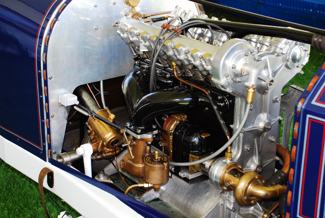
#14 Peugeot Motor, photograph by Geoffrey Horton at Palo Alto in 2011.
With out wishing to disturb the essential character of this thread I'm wondering if anyone could confirm if the car raced by Duray in 1914 had any racing history prior to it being acquired by the Menier family and I wonder if anyone can remember the name of "of the guy with the peculiar name" that Doug could not recall in post 24 above ?
Relevant answers may be credited and used in a forth coming blog.
Thanking you in anticipation of your responses.
Edit: Correction to original '#16' which of course was the number of the winning René Thomas Delage

Edited by arttidesco, 16 April 2013 - 14:32.
#29
Doug Nye
-
- 11,535 posts
- Joined: February 02
Member
Posted 16 April 2013 - 19:04
I wonder if anyone can remember the name of "of the guy with the peculiar name" that Doug could not recall in post 24 above ?
After its Indy days there is some suggestion it returned to France, plus a parallel suggestion that it stayed in the US. Sold to Harry Harkness who ran it a little in the north-eastern area, then sold to Kaufman, himself a New York Peugeot agent and team owner. The engine might have been "swapped out" of the chassis at some stage. Car then found at Benny Brandfon’s yard for old race cars and exotics in NY...
'Brandfon' was the 'peculiar name' I struggled to recall.
Info courtesy Scott George at The Collier Collection.
DCN
Edited by Doug Nye, 16 April 2013 - 19:08.
#30
arttidesco
-
- 6,709 posts
- Joined: April 10
Member
Posted 16 April 2013 - 19:11
After its Indy days there is some suggestion it returned to France, plus a parallel suggestion that it stayed in the US. Sold to Harry Harkness who ran it a little in the north-eastern area, then sold to Kaufman, himself a New York Peugeot agent and team owner. The engine might have been "swapped out" of the chassis at some stage. Car then found at Benny Brandfon’s yard for old race cars and exotics in NY...
'Brandfon' was the 'peculiar name' I struggled to recall.
Info courtesy Scott George at The Collier Collection.
DCN
Most kind Doug, how many bags of nuts do I owe you now ?
#31
Steve L
-

- 547 posts
- Joined: October 02
Member
Posted 17 April 2013 - 17:47
Incidentally - the Peugeot engine mounting system is fascinating. The legendary 4-valves per cylinder/hemispherical combustion chamber engine does not bolt - conventionally - via cast-on legs or lugs directly into the forepart of the chassis frame.
Instead it bolts into a separate and lengthy U-shaped sub-frame member which is pivoted up front on the curve of the U onto the chassis' front cross-member, via a kind of gimbal bearing. The rear extremity of each leg of this U - which extends rearwards within the space between the chassis side-frames - is then attached to those main rails on each side via another gimbal bearing.
This must have freed the crankcase casting from torsional stresses within the frame. The front end of the chassis frame itself, meanwhile, is stiffened at each front corner by heftily dimensioned thick steel triangular plates rigidly attached.
There's a whole lot more to these ingenious cars than perhaps one finds in the cold print of most of our history books.
DCN
I would love to see some pictures of this arrangement if any are available please

#32
arttidesco
-
- 6,709 posts
- Joined: April 10
Member
Posted 17 April 2013 - 19:16
I would love to see some pictures of this arrangement if any are available please
Not something I can help you with from the five pics Geoffrey Horton sent me I am afraid.
While I was checking I did notice what appears to be a 21st Century digital device held clamped on to the front axle with what appears to be a period G clamp,
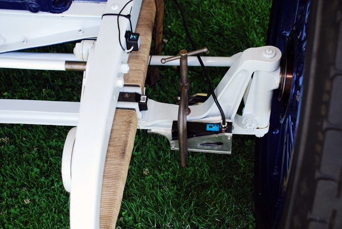
would anybody be able to hazard a guess what the black box is for ?
#33
Michael Ferner
-

- 7,203 posts
- Joined: November 09
Member
Posted 18 April 2013 - 16:16
A timing device, perhaps?
#34
arttidesco
-
- 6,709 posts
- Joined: April 10
Member
Posted 03 May 2013 - 07:37
A timing device, perhaps?
Turns out the sensor was attached to a computer by students of the Revs Programme at Stanford University for vehicle dynamics testing.
Thanks to Doug for his contribution to yesterdays blog


