Jump to content


Photo
* * - - - 5 votes

New engine


  • Please log in to reply
2073 replies to this topic

#551 Feliks

Feliks
  • Member

  • 1,033 posts
  • Joined: December 04

Posted 29 March 2011 - 12:12

Hi Andrew. If you point a 6m diameter frictionless pipe into a 5.8m/s wind you will get the massflow calculated (200 kg/s). If you reduce the diameter at some point along the pipe you will get less massflow. (If your venturi is 1.8m diameter the flow will be a LOT less than 200 kg/s.)


I see that you do not know the rules of venturi nozzle. The flow of 200 kg / sec will be maintained at its narrowest point, because there the velocity grows more than 10 times. And that's what makes this speed raised to the third power makes such a huge increase obtained for its use of energy.

We only have to insert there similarly constructed durable turbine engine as Harrier. because its diameter is not much larger.
And besides, how will the wind of 15 m / sec, the flow will be 600 kg / sec.....

Andrew :smoking: :smoking:

Advertisement

#552 cheapracer

cheapracer
  • Member

  • 10,388 posts
  • Joined: May 07

Posted 29 March 2011 - 12:23

I see that you do not know the rules of venturi nozzle.


Posted Image

DING!

#553 Feliks

Feliks
  • Member

  • 1,033 posts
  • Joined: December 04

Posted 29 March 2011 - 12:37

Another way to go. The narrowest point is less Venturiego nozzle pressure. It's like found in the center of the lowlands of atmospheric ( weather ). This causes larger than hurricanes weather.
Except that here we have a much shorter way from the boom to the lowlands....
Huricane flows from areas of high pressure to areas of low pressure.

Andrew :smoking: :smoking:

Edited by Feliks, 29 March 2011 - 12:38.


#554 Feliks

Feliks
  • Member

  • 1,033 posts
  • Joined: December 04

Posted 29 March 2011 - 12:43

DING!


After a few seconds, I was victorious FOR IN Technical knockout

DING

Andrew

Edited by Feliks, 29 March 2011 - 12:45.


#555 gruntguru

gruntguru
  • Member

  • 7,642 posts
  • Joined: January 09

Posted 29 March 2011 - 14:53

I see that you do not know the rules of venturi nozzle. The flow of 200 kg / sec will be maintained at its narrowest point, because there the velocity grows more than 10 times. And that's what makes this speed raised to the third power makes such a huge increase obtained for its use of energy.

We only have to insert there similarly constructed durable turbine engine as Harrier. because its diameter is not much larger.
And besides, how will the wind of 15 m / sec, the flow will be 600 kg / sec.....

Andrew :smoking: :smoking:

You don't need to understand venturi rules. Read CAREFULLY.

1. Place a 6m diameter pipe facing the 5.8 m/s wind. Flow = 200kg/s.
2. Now put a restriction 1.8 m in diameter somewhere inside the pipe. THE FLOW WILL DECREASE. ie it is now less than 200 kg/s REGARDLESS OF Cd.

Edited by gruntguru, 29 March 2011 - 14:54.


#556 cheapracer

cheapracer
  • Member

  • 10,388 posts
  • Joined: May 07

Posted 29 March 2011 - 15:11

1. Place a 6m diameter pipe facing the 5.8 m/s wind. Flow = 200kg/s.
2. Now put a restriction 1.8 m in diameter somewhere inside the pipe. THE FLOW WILL DECREASE. ie it is now less than 200 kg/s REGARDLESS OF Cd.


Posted Image

#557 gruntguru

gruntguru
  • Member

  • 7,642 posts
  • Joined: January 09

Posted 29 March 2011 - 15:20

Float like a butterfly . . .

#558 Feliks

Feliks
  • Member

  • 1,033 posts
  • Joined: December 04

Posted 29 March 2011 - 16:10

Float like a butterfly . . .


O yes. you right .my be 199 kg/sec. Select Venturi type : welded tube or machined.


So what will the mass flow exiting the venturi nozzle?

Andrew :rolleyes:

#559 Greg Locock

Greg Locock
  • Member

  • 6,366 posts
  • Joined: March 03

Posted 29 March 2011 - 21:25

O yes. you right .my be 199 kg/sec.

So what will the mass flow exiting the venturi nozzle?


Step back from the equations, and think about what would happen if you put a disc with a hole in it up to the airflow. Now stretch the disc out along the axis of the hole. All the air in the disc bit will be still 'see' disc ahead of them, not the hole you'd like them to go for. A big wodge of stagnated air will build up ahead of the venturi. For the equations just use continuity and Bernouilli, for the lossless case.


Advertisement

#560 Feliks

Feliks
  • Member

  • 1,033 posts
  • Joined: December 04

Posted 29 March 2011 - 22:37

Step back from the equations, and think about what would happen if you put a disc with a hole in it up to the airflow. Now stretch the disc out along the axis of the hole. All the air in the disc bit will be still 'see' disc ahead of them, not the hole you'd like them to go for. A big wodge of stagnated air will build up ahead of the venturi. For the equations just use continuity and Bernouilli, for the lossless case.


In this reasoning, the disc does not have thickness. The reasoning for the classic windmill, to which all are used: flat disk, with virtually no thickness. Therefore, the classic windmill has a low efficiency, because this disc is not dispensed air mass and its speed is only such as wind.
The venturi nozzle are two cones and a not insignificant thickness of 25 meters. And now this whole mass of air that is housed in a venturi nozzle is involved in the flow through it. It should be noted that the cones are of unequal length. Cone output is 30 % longer than the input... why? Well, because this is the output cone of doing it at low pressure in the narrowest point.
With reduction in pressure, is involved the whole mass of air in which the output is a cone, that is, the average disk X 16m. Cone can not be shorter because they do not provide laminar flow, which is a prerequisite for good work Venturi nozzle. With disorders of movement ( for a short cone ) in action will take part, only a small mass of air, to lower pressure. The condition is llaminar flow, because the cone has to be quite so long. For that produces a significant vacuum in the narrowest point, causing fresh air to the input cone...

Andrew :smoking: :smoking:

Edited by Feliks, 29 March 2011 - 22:50.


#561 gruntguru

gruntguru
  • Member

  • 7,642 posts
  • Joined: January 09

Posted 30 March 2011 - 00:11

The total kinetic energy in a 6m diameter cylinder of wind at 5.8 m/s is (mv^2)/2 = (200kg x 5.8m/s^2)/2 = 3.36 kW. At the small diameter of your venturi the kinetic energy is (200kg x 64.67m/s^2)/2 = 418 kW. Your machine has created a lot of energy from "thin air".

Why didn't you use an even smaller diameter at the throat of your venturi? Every time you halve the diameter the area reduces by 1/4, the velocity increases by 4 times and the power by 16 times!

The venturi calculator you used is for pipe flow - the air coming into the venturi cannot bypass the pipe like free atmospheric air can. The power required to drive this "venturi-in-a-pipe" is (approximately)
= delta P x Volumetric flow rate.
= (P1 - P2) x V x A
= (1.0332274 Atm - 1.0065 Atm) x 101 kPa/Atm x 5.8 m/s x Pi x 3m x 3m
= 442.7 kW.

That's a very powerful fan required to generate the "free" energy you hope to extract further downstream.

Edited by gruntguru, 30 March 2011 - 04:22.


#562 Feliks

Feliks
  • Member

  • 1,033 posts
  • Joined: December 04

Posted 30 March 2011 - 13:02

Posted Image

Regards Andrew


Another way .

The most significant is the speed at narrowest place.
Because the speed of local government units in the formula for the power of the windmill to the third power.

normal widmil: 5 X 5 X 5 X 6 X 6 / 1530 X 0,4 = 2,94 HP

Venturi widmil : 64 X 64 X 64 X 1,8 X 1,8 / 1530 X 0,8 = 441 HP

And it is not energy from nowhere, but its use is much more appropriate when the wind velocity


Andrew :smoking: :smoking:

Edited by Feliks, 30 March 2011 - 13:05.


#563 Wuzak

Wuzak
  • Member

  • 8,507 posts
  • Joined: September 00

Posted 30 March 2011 - 21:29

Another way .

The most significant is the speed at narrowest place.
Because the speed of local government units in the formula for the power of the windmill to the third power.

normal widmil: 5 X 5 X 5 X 6 X 6 / 1530 X 0,4 = 2,94 HP

Venturi widmil : 64 X 64 X 64 X 1,8 X 1,8 / 1530 X 0,8 = 441 HP

And it is not energy from nowhere, but its use is much more appropriate when the wind velocity


Andrew :smoking: :smoking:


Andrew, what the guys are telling you is that to get the 56m/s at the throat and 5m/s at the entrance of the venturi system the freestream air has to have more speed/energy than the air at 5m/s. That the air at the intake will be significantly slowed by the back pressure of the venturi, and that effect will be even worse with a fan inside.

Does anybody have CFD to graphically show what happens?

Edited by Wuzak, 30 March 2011 - 21:30.


#564 Greg Locock

Greg Locock
  • Member

  • 6,366 posts
  • Joined: March 03

Posted 30 March 2011 - 21:55

Andrew the equation for a venturi is easily googled. It will reveal the not very astonishing fact that if you don't put any energy into the free flowing fluid, you won't get any more out.


#565 Feliks

Feliks
  • Member

  • 1,033 posts
  • Joined: December 04

Posted 30 March 2011 - 23:31

...air has to have more speed/energy than the air at 5m/s. .....
Does anybody have CFD to graphically show what happens?


...air has to have more speed/energy than the air at 5m/s (speed) :lol:

Speed ​​or energy, because it's two different concepts. ?

The amount of energy is constant, but the rate differs 10 times.

Only traditional windmill at such low speeds are not used in wind energy, even at 5 %

Fan in the middle, actually conceal a little, but it will depend on the number of blades, etc. should be counted in the Venturi nozzle, then, as if the cross at the narrowest point was lower. Then for sure the exhaust cone is longer, in order to keep the flow laminary.

Draw a traditional windmill drive, and draw his blade. You will see that they are not even 5% of the disk surface. How to make even the low speed wind... it is primitive :rotfl:


Andrew :smoking: :smoking:

What is Back Presure in venturi nozzle ? Probably a mistake from the spot vacuum at the narrowest point.


Edited by Feliks, 30 March 2011 - 23:40.


#566 Greg Locock

Greg Locock
  • Member

  • 6,366 posts
  • Joined: March 03

Posted 30 March 2011 - 23:47

Draw a traditional windmill drive, and draw his blade. You will see that they are not even 5% of the disk surface. How to make even the low speed wind... it is primitive :rotfl:


It may be primitive but it works. Froude did a lot of measurements on the efficiency of propellers, and found that the Blade Area Ratio has an astonishingly small effect on the power output of a prop. This is because the extra friction from the larger blades offsets the extra power drawn from the air.

In addition, a definition of efficincy for a system where the input side is effectively unlimited is rather different than one for a car, where you pay directly for the fuel.

SO the optimum windmill is the one that creates the most power for the money spent (perhaps), rather than the one that extracts the maximum %age of the available enegry in the local airstream. The latter is an engineering efficincy, the former is the one that'll feed your grandchildren.


#567 gruntguru

gruntguru
  • Member

  • 7,642 posts
  • Joined: January 09

Posted 30 March 2011 - 23:48

If you can't get your head around the theory, at least try this. Build two models. Model 1 is a cylinder, model 2 is the same cylinder with a venturi built into it. Put one model in a steady breeze and use a mosquito coil to see where the air goes. Repeat for the other model. Depending on the throat diameter in the venturi you will see that most of the air approaching the venturi actually dodges around it instead of going through.

To add to my previous post. The maximum pressure difference available to drive your venturi is the stagnation pressure given by P(static) = (rho x v x v)/2 (Bernouilli)
= (1.2 x 5.8 x 5.8)/2
= 20 Pa.

The pressure difference required in your venturi calculator (post 548) is 1.0332274 - 1.0065 = 0.0267 Bar = 2699 Pa. So the 20 Pa available in the wind will never drive your venturi - like I said you need to add a 442 kW fan at the inlet.

(No mistake on the back pressure. As I showed in my previous post, that is how much pressure is required to accelerate 200 kg/s from 5.8 m/s to 64 m/s.)

Edited by gruntguru, 30 March 2011 - 23:52.


#568 gruntguru

gruntguru
  • Member

  • 7,642 posts
  • Joined: January 09

Posted 30 March 2011 - 23:52

It may be primitive but it works. Froude did a lot of measurements on the efficiency of propellers, and found that the Blade Area Ratio has an astonishingly small effect on the power output of a prop. This is because the extra friction from the larger blades offsets the extra power drawn from the air.

In addition, a definition of efficincy for a system where the input side is effectively unlimited is rather different than one for a car, where you pay directly for the fuel.

SO the optimum windmill is the one that creates the most power for the money spent (perhaps), rather than the one that extracts the maximum %age of the available enegry in the local airstream. The latter is an engineering efficincy, the former is the one that'll feed your grandchildren.

To add to that, modern wind turbines operate at extraordinarily high efficiency. The number of blades is the maximum possible without each blade operating in the wake of the previous blade.

#569 Feliks

Feliks
  • Member

  • 1,033 posts
  • Joined: December 04

Posted 31 March 2011 - 00:22

[quote name='gruntguru' date='Mar 30 2011, 23:48' post='4932073']
If you can't get your head around the theory, at least try this. Build two models. Model 1 is a cylinder, model 2 is the same cylinder with a venturi built into it. Put one model in a steady breeze and use a mosquito coil to see where the air goes. Repeat for the other model. Depending on the throat diameter in the venturi you will see that most of the air approaching the venturi actually dodges around it instead of going through.

/Quote

This is not true that entrusting will mostly bypass the Venturi nozzle.


Why? because in a venturi nozzle at the narrowest point a vacuum (vacuum ). THIS IS Venturi nozzle base theory - Reduced pressure.
And it is, however, causes a vacuum sucking the air in most of the drive input.

What causes the formation of low pressure - sent the momentum of the air in the output cone - P = M x V .

This drive is very high because the air mass in the cone output is also high - the average disk X 16 meters x 1 kg.

Andrew :smoking: :smoking:

Posted Image


Edited by Feliks, 31 March 2011 - 00:48.


#570 gruntguru

gruntguru
  • Member

  • 7,642 posts
  • Joined: January 09

Posted 31 March 2011 - 00:40

This is not true that entrusting will mostly bypass the Venturi nozzle.

Are you a gambling man? A small wager perhaps?

#571 Feliks

Feliks
  • Member

  • 1,033 posts
  • Joined: December 04

Posted 31 March 2011 - 00:58

Are you a gambling man? A small wager perhaps?


No mostly , little yes.


These small losses, for example, air friction losses walls of the nozzle.


Andrew :smoking: :smoking:


#572 gruntguru

gruntguru
  • Member

  • 7,642 posts
  • Joined: January 09

Posted 31 March 2011 - 01:01

These small losses, for example, air friction losses walls of the nozzle.

No they are not. The downstream restriction causes an increase in pressure at the entry. This increased pressure bends the streamlines so most of the wind turns and goes around the pipe not through it.

#573 Feliks

Feliks
  • Member

  • 1,033 posts
  • Joined: December 04

Posted 31 March 2011 - 01:17

No they are not. The downstream restriction causes an increase in pressure at the entry. This increased pressure bends the streamlines so most of the wind turns and goes around the pipe not through it.


I have not read anywhere else, lest the input was increased pressure. Why is that supposed to be so, since 10 meters is an area of ​​very low pressure. Rather, it predisposes to a hurricane....
I created....


Andrew :wave:


#574 Greg Locock

Greg Locock
  • Member

  • 6,366 posts
  • Joined: March 03

Posted 31 March 2011 - 01:56

Andrew, up til now I've read most of your posts with interest. However, if you really persist in this bizarre line of attack on well established physics, it means that everything else you've written could be seriously cracked. Is it really worth maintaining some attempt at a verbal argument when the maths is well known, relatively trivial (Bernouilli and mass continuity), and you are destroying your credibility?

Edited by Greg Locock, 31 March 2011 - 02:28.


#575 gruntguru

gruntguru
  • Member

  • 7,642 posts
  • Joined: January 09

Posted 31 March 2011 - 04:21

I have not read anywhere else, lest the input was increased pressure. Why is that supposed to be so, since 10 meters is an area of ​​very low pressure.

Unfortunately the very low pressure you imagine does not exist unless you achieve the 64 m/s velocity. There is not enough energy in the wind to accelerate it to that velocity so you won't get the low pressure either.

Conservation of energy.

Power in freestream (6m dia) = Power at throat

1/2MVf^2 = 1/2MVt^2
1/2 x (rho x Af x Vf) x Vf^2 = 1/2 x (rho x At x Vt) x Vt^2
Af x Vf^3 = At x Vt^3
Vt = (Af/At x Vf^3)^1/3
Vt = (36/3.2 x 5.8^3)^1/3
Vt = 13 m/s (A lot less than 64 m/s)
(M=mass flow Vf=freestream velocity Vt=throat velocity Af=freestream area harnessed At=throat area)

Massflow is 40 kg/s not 199. These are high end numbers assuming all the energy in a 6m diameter "sausage" of wind approaching the venturi, ends up in the throat. In reality, the theoretical maximum is only 69% of that (Betz's law) and a real machine will not even achieve that much.

#576 Feliks

Feliks
  • Member

  • 1,033 posts
  • Joined: December 04

Posted 31 March 2011 - 08:44

Unfortunately the very low pressure you imagine does not exist unless you achieve the 64 m/s velocity. There is not enough energy in the wind to accelerate it to that velocity so you won't get the low pressure either.

Conservation of energy.


[/i]Massflow is 40 kg/s not 199. These are high end numbers assuming all the energy in a 6m diameter "sausage" of wind approaching the venturi, ends up in the throat. In reality, the theoretical maximum is only 69% of that (Betz's law) and a real machine will not even achieve that much.


"does not exist " - plane not flying, carburator is not work and Fukushima not dangerous :lol:

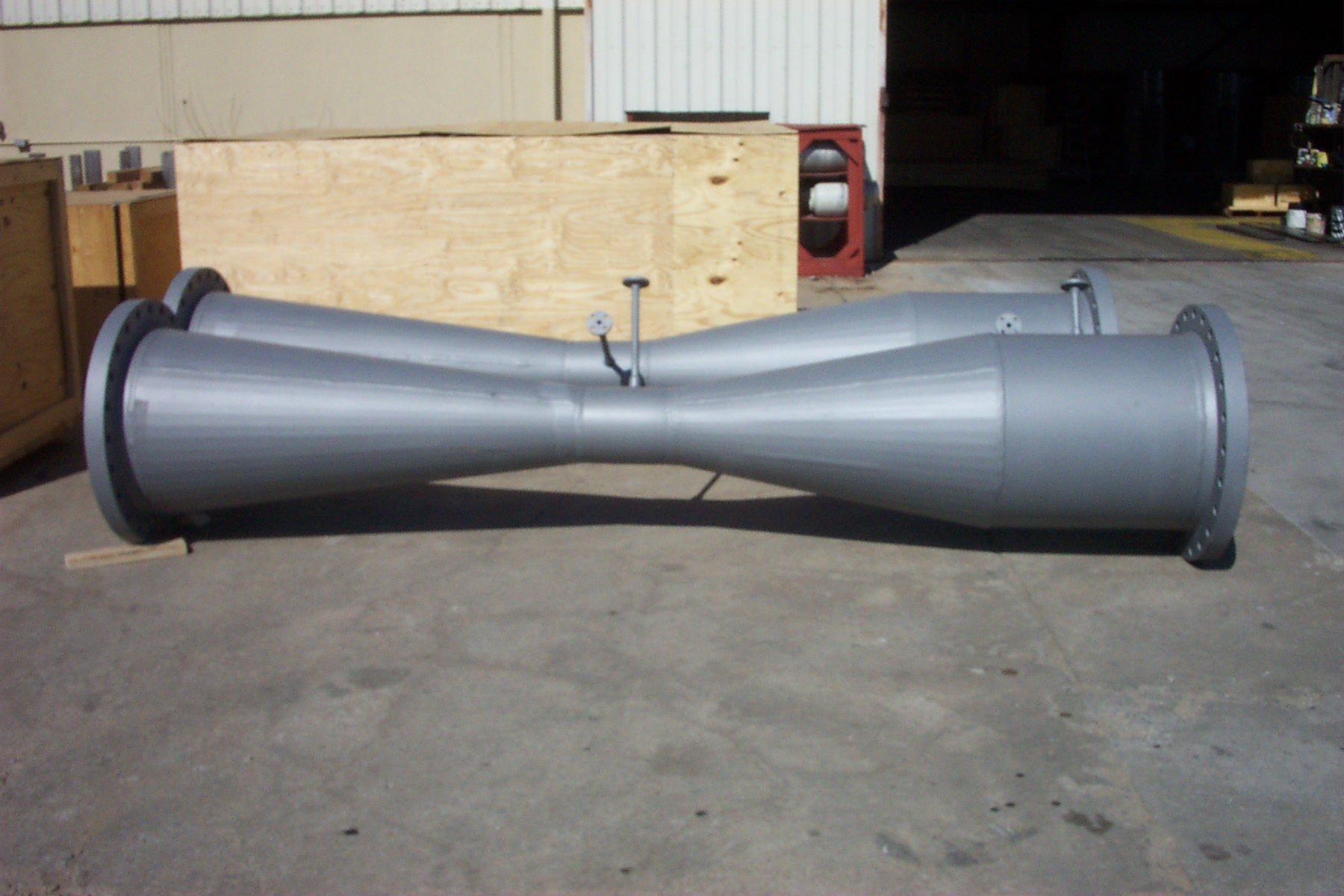
However, few venturi nozzle in the world already taken:

Posted Image

Posted Image

Posted Image


Posted Image


And that's all this, lest the narrowest point of the birds can build a nest :rolleyes:


Andrew :smoking: :smoking:

#577 gruntguru

gruntguru
  • Member

  • 7,642 posts
  • Joined: January 09

Posted 31 March 2011 - 13:21

Nice photos. OK so venturis do exist!

Design a scale model of your venturi. Check the numbers in your venturi design calculator - you will see that scaling down does not affect the results. Build the model and test it.

#578 Feliks

Feliks
  • Member

  • 1,033 posts
  • Joined: December 04

Posted 31 March 2011 - 13:47

Nice photos. OK so venturis do exist!

..... Build the model and test it.


Open a new faculty at universities

Andrew :wave:


#579 Feliks

Feliks
  • Member

  • 1,033 posts
  • Joined: December 04

Posted 01 April 2011 - 13:43

If you need a really high torque without gear:


Posted Image

Regards Andrew :smoking: :smoking:


Advertisement

#580 Greg Locock

Greg Locock
  • Member

  • 6,366 posts
  • Joined: March 03

Posted 02 April 2011 - 01:01

If you need a really high torque without gear:


Posted Image

Regards Andrew :smoking: :smoking:

Oh, one of these you mean? http://www.csiro.au/...rces/pf11g.html How many do you want?

#581 Feliks

Feliks
  • Member

  • 1,033 posts
  • Joined: December 04

Posted 02 April 2011 - 07:41

Now he will show and I will explain the rule of operation my new dynastarter :


Posted Image


Next on hard PCB put some coils end electronics.
every so the "green cylinder" has the magnet, two tubules with shuffled teeth for the half of their size of the division, a bit electronics of the type small bridge on mossfets, securities on varistors electronics controlling generate the electricity . Current on each coil about 5 Ampers menage mossfets.
Everything contloled of course with microprocessor .


Posted Image


It is put on this hard PCB plate about 150 of such arrangements with coils and the electronics parts

Posted Image


everyone so complet of elements is decreeing with 5 amperes, rally if to do about 150 pieces of these elements and to put them on this PCB tile, we can manage about 750 amperes what should completely be enough for the warming up the engine. Receiving the electric current in the same way for charging a battery is already a banally simple matter.

Posted Image

I think, that such PCB it "Automotive mother board" the same "Automotive mother board" is replacing the alternator and the starter. Flywheel still is always in the engine.

Posted Image


Principe as same , but in disc version linear stepper

Regards Andrew :smoking: :smoking:


Oh no, rather it. Several times a better momentum and more modern electronics ....


Andrew :smoking: :smoking:

#582 MatsNorway

MatsNorway
  • Member

  • 2,822 posts
  • Joined: December 09

Posted 03 April 2011 - 19:37

Thats just a linear motor wrapped around a thing isn`t it?

http://www.youtube.c...detailpage#t=7s

Very expensive stuff.

#583 Greg Locock

Greg Locock
  • Member

  • 6,366 posts
  • Joined: March 03

Posted 03 April 2011 - 22:44

The motor I linked to is 98% efficient, and costs 12000 dollars, for a 5 kW unit. However, the real cost in production would be more like $500, and quite seriously I'd expect Cheapy to knock them out for 1/3 of that. Most of that cost is the rare earth magnets, I'd guess you could halve the magnet cost for a 3% reduction in efficiency by using an iron backplate.

Andrew's motor ina flywheel is already available. For that matter a zillion years ago there was Dynastart.


#584 cheapracer

cheapracer
  • Member

  • 10,388 posts
  • Joined: May 07

Posted 04 April 2011 - 06:06

The motor I linked to is 98% efficient, and costs $12000 dollars, for a 5 kW unit. However, the real cost in production would be more like $500, and quite seriously I'd expect Cheapy to knock them out for 1/3 of that.


Ok, how many you want at $4000?

#585 mariner

mariner
  • Member

  • 2,334 posts
  • Joined: January 07

Posted 04 April 2011 - 08:42

A neat trick on this sort of " pancake" shaped motor would be to design it so it can also be the disc brake rotor at each wheel. That way you eliminate most of the electric motor net weight penalty as vented discs ( up to four of them ) are one of the heaviest items on a chassis.

I suspect it would be hard to do because whilst the heat soak pattern is potentially attractive ( you either heat the core up on acceleration OR braking but never together) the heat range for a brake disc would push any electrical components to the very limit.

Good if it could be done though.

#586 Feliks

Feliks
  • Member

  • 1,033 posts
  • Joined: December 04

Posted 04 April 2011 - 11:55

Straight structure of dynastarter brought the thought to mind for me in order on the similar principle to do electric brakes and the electric assisting engine on the not-drived pivot of the car .
Instead of the flywheel I used the brake disc from one side having small teeth made an incision.

They are also put on the PCB plate green "pins" in the bulk. http://www.new4stroke.com/greenpin.jpg

Posted Image

Such an arrangement allows on not-drived pivot to carry the electric brake out also. Yeah but very much work opportunities of such an arrangement are also an important case on not-drived pivots, as the electric motor driving wheels directly. Perhaps it won't be such an excellent drive as classical 4 x 4, but in critical situations can replace such a four-drive arrangement. I think that it is possible to name him 2 + 2.

And have a electronic lock.... simile ABS

Regards Andrew :smoking: :smoking:


A neat trick on this sort of " pancake" shaped motor would be to design it so it can also be the disc brake rotor at each wheel. That way you eliminate most of the electric motor net weight penalty as vented discs ( up to four of them ) are one of the heaviest items on a chassis.

I suspect it would be hard to do because whilst the heat soak pattern is potentially attractive ( you either heat the core up on acceleration OR braking but never together) the heat range for a brake disc would push any electrical components to the very limit.

Good if it could be done though.


Andrew :smoking: :smoking:


#587 Feliks

Feliks
  • Member

  • 1,033 posts
  • Joined: December 04

Posted 04 April 2011 - 12:49

Nice photos. OK so venturis do exist!

Design a scale model of your venturi. Check the numbers in your venturi design calculator - you will see that scaling down does not affect the results. Build the model and test it.


Vinturi Wine Pourer

Andrew :wave:


#588 Feliks

Feliks
  • Member

  • 1,033 posts
  • Joined: December 04

Posted 04 April 2011 - 19:04

If they move to the Thames this venturi nozzle:

D=1 meter, L = 5 meter V min 0,6 m/sec V max 6 m/sec , Flow 500 kg/sec .....

A little power except that she did....

The same goes for the sea tidal and sea currents.

Regards Andrew :smoking: :smoking:

Edited by Feliks, 04 April 2011 - 21:00.


#589 Feliks

Feliks
  • Member

  • 1,033 posts
  • Joined: December 04

Posted 09 April 2011 - 01:18

Animation showing how using venturi nozzle drives the gyroscope to the flight instruments. Historically, the aircraft was not an electric current...
But now, if we do the jets in the right size, we thus also powered electric generator...


Posted Image


Even used a double Venturi nozzle, in order to increase the vacuum to best drive "turbine"


Posted Image


Regards Andrew :smoking: :smoking:


#590 Wuzak

Wuzak
  • Member

  • 8,507 posts
  • Joined: September 00

Posted 09 April 2011 - 03:55

I did a SW simulation (FEA) training course last week, and was able to play with Flow Simulation during breaks. So I modelled a venturi tube, inlet and outlet diameter of 5m, throat diameter of 1m and a free air speed of 5m/s.

I don't know how good the flow sim is, but the results still, IMO, show what Greg and Grubt have been saying about the operation of a vnturi tube wind generator.

For some reason I cannot use the on-line venturi calculator. But I will give an estimate.

Ignoring other effects the flow velocity will increase in proportion to the square of the diameter change - ie V2/V1 = (D1/D2)^2

Thus, for an initial velocity of 5m/s and a change in diameter from 5m to 1m the flow velocity in the throat is 125m/s.

So, to compare Power.

In the free stream the power is P = 0.5 * rho * pi*D^2/4*V^3*eff = 0.5*1.2*pi*25/4*125*0.4 = 0.59kW

In the throat of the venturi the power is P = 0.5*1.2*pi*1/4*1953125*0.4 = 368kW.

But if we look at the flow simulation results:

Posted Image

We can see that the air velocity is much reduced before the air enters the tube, the stagnation zone, and the maximum flow velocity at the throat is 10.678m/s - someway below the theoretical predicted. The air flow in teh entrance part of the pipe has dropped from the free stream velocity of 5m/s to around 15-2.5m/s.

Plugging that back into the equation P = 0.5*1.2*pi*1/4*10.768^2*0.4 = 0.23kW

The power available at the throat is much reduced (to about 30%) due to aerodynamic considerations.

This diagram is of flow trajectories, and it shows that on the exit side of the venturi there is some turbulance.

Posted Image

This diagram also shows that the diameter of free air that actually works its way through teh venturi is much smaller than the entrance diameter of 5m.

#591 gruntguru

gruntguru
  • Member

  • 7,642 posts
  • Joined: January 09

Posted 09 April 2011 - 04:25

We can see that the air velocity is much reduced before the air enters the tube, the stagnation zone, and the maximum flow velocity at the throat is 10.678m/s - someway below the theoretical predicted.

Nice analysis Wuzak. In post #575 above I showed that conserving all of the energy in the 6m diameter free stream results in a throat velocity of 13 m/s. Betz's law says that the power in the throat will be less than 69% of this. Power is proportional to velocity cubed so the maximum velocity in the throat would be [(13^3) x 0.69]^1/3 = 11.48 m/s. This agrees nicely with the 10.678 you have simulated for a "real" machine which is unlikely to approach the theoretical maximum given by Betz's law.

#592 Wuzak

Wuzak
  • Member

  • 8,507 posts
  • Joined: September 00

Posted 09 April 2011 - 05:37

Nice analysis Wuzak. In post #575 above I showed that conserving all of the energy in the 6m diameter free stream results in a throat velocity of 13 m/s. Betz's law says that the power in the throat will be less than 69% of this. Power is proportional to velocity cubed so the maximum velocity in the throat would be [(13^3) x 0.69]^1/3 = 11.48 m/s. This agrees nicely with the 10.678 you have simulated for a "real" machine which is unlikely to approach the theoretical maximum given by Betz's law.


Thanks grunt.

I was going to try a couple of different free stream velocities - say 2.5m/s and 10m/s - to see if the stagnation zone worsened, and to see how much the throat speed changed - would doubling the free stream velocity double the throat velocity.

I would suspect that for a doubling of free stream velocity the throat velocity would be less than double. And if the wind could go fast enough then there would be a stage where the throat velocity would reach a maximum, and no increase in free stream velocity would increase the throat velocity. Though the wind may have to be doing an unrealistic velocity for that to occur.

I did get a pressure plot, but it isn't a great picture. The maximum pressure charted was 101.35kPA at the entrance of the venturi, to a minimum of 101.27kPa at the throat.

#593 gruntguru

gruntguru
  • Member

  • 7,642 posts
  • Joined: January 09

Posted 09 April 2011 - 10:51

I was going to try a couple of different free stream velocities - say 2.5m/s and 10m/s - to see if the stagnation zone worsened, and to see how much the throat speed changed - would doubling the free stream velocity double the throat velocity?

I think it would. In simplest terms for small throat diameters - the pressure at the entry will be stagnation pressure since the entry velocity will be much less than the free-stream velocity. Stagnation pressure is proportional to V squared. The flow through the venturi will then be driven by that pressure and the velocity in the throat will be proportional to the square root of the pressure - ie proportional to free-stream velocity.

I would suspect that for a doubling of free stream velocity the throat velocity would be less than double. And if the wind could go fast enough then there would be a stage where the throat velocity would reach a maximum, and no increase in free stream velocity would increase the throat velocity. Though the wind may have to be doing an unrealistic velocity for that to occur.?

I don't think there will be any "choking" - at least in the subsonic region. I am rusty on supersonic flow theory but there may be some effect as you approach Mach 1.

#594 Feliks

Feliks
  • Member

  • 1,033 posts
  • Joined: December 04

Posted 09 April 2011 - 13:24

Open a new faculty at universities

Andrew :wave:


I think that before the creation of such faculty, today is good day for the opening lecture. :rolleyes:


But first.

I did a SW simulation (FEA)... In the free stream the power is P = 0.5 * rho * pi*D^2/4*V^3*eff = 0.5*1.2*pi*25/4*125*0.4 = 0.59kW

In the throat of the venturi the power is P = 0.5*1.2*pi*1/4*1953125*0.4 = 368kW.

But if we look at the flow simulation results:


That " something " which did a simulation, it is not a venturi nozzle. This is a restrictor " Wuzak ", because it is absolutely symmetrical. Well, the simulations can see that there is no exact turbolent flow which will prevent proper operation in line with expectations. :smoking:
http://www.flowmeter...nturi_calc.html
You must have Java


So yes, I think it best to start with what everyone has long-standing knowledge and know how not to reinvent the wheel.
Ideally we'll see this in professional.

http://www.croll.com/pr/pdf/vacpro.pdf
http://www.croll.com...f/fundament.pdf
http://www.croll.com...vetheory#matcon
http://www.croll.com.../DesigSteam.pdf

http://www.croll.com/pr/a_ejectors.htm
http://www.croll.com...pdf/vacpump.pdf
http://www.croll.com...df/vacwater.pdf
http://www.croll.com...uperheaters.pdf
http://www.croll.com...oisecontrol.pdf

I think that for the first time, that's enough. :rolleyes:


Posted Image

Regards Yoda


Andrew :smoking: :smoking:

Edited by Feliks, 09 April 2011 - 13:26.


#595 Wuzak

Wuzak
  • Member

  • 8,507 posts
  • Joined: September 00

Posted 09 April 2011 - 14:33

That " something " which did a simulation, it is not a venturi nozzle. This is a restrictor " Wuzak ", because it is absolutely symmetrical. Well, the simulations can see that there is no exact turbolent flow which will prevent proper operation in line with expectations. :smoking:


Here's a definition of a venturi from The Free Dictionary:

ven·tu·ri
n. pl. ven·tu·ris
1. A short tube with a constricted throat used to determine fluid pressures and velocities by measurement of differential pressures generated at the throat as a fluid traverses the tube.
2. A constricted throat in the air passage of a carburetor, causing a reduction in pressure that results in fuel vapor being drawn out of the carburetor bowl.


Doesn't say anything about the venturi needing to be asymmetric. In fact I doubt that most are anything other than symmetric.

Most ventruis are used in pipe sections, and used for local flow measurement. They are used for this because of the pressure difference between the main flow and the throat is measureable and consistent - at least in incompressible (or nearly so) fluids.

If I made the test sample a straight piece of pipe, with the same ID and OD along the same length as the venturi it would have had the same aerodynamic effects at the inlet, leading to a reduction in flow velocity through the pipe compared with the free stream velocity.

It has been suggested you do some experiments in previous posts.

You could build something like this: Posted Image

There are several points for pressure measurements so a pressure distribution along the pipe's length would easily be determined. I'd suggest you lose the pipe flanges at each end when you test the pipe in the wind tunnel (or in front of a fan).

Not sure the vacuum generating solutions are relevent to the problem of using a venturi to (hopefully) increase the power that can be generated by the wind.


http://www.flowmeter...nturi_calc.html
You must have Java


I do have Java.

#596 gruntguru

gruntguru
  • Member

  • 7,642 posts
  • Joined: January 09

Posted 10 April 2011 - 04:20

That " something " which did a simulation, it is not a venturi nozzle. This is a restrictor " Wuzak ", because it is absolutely symmetrical. Well, the simulations can see that there is no exact turbolent flow which will prevent proper operation in line with expectations. :smoking:

So if Wuzak moves the throat section upstream a little and thus reduces the diffuser angle a little, you think the velocity in the throat will improve from 10.6 m/s to 64 m/s??? (You are expecting the throat velocity to improve by a factor of 6.03 and the power by a factor of 220!)

You don't think it interesting that Wuzak's CFD simulation agrees quite closely with my earlier calculations?

You don't think engineers and scientists around the world have already considered and tested what happens when you place a venturi in the wind?

You don't recognise that some of the people trying to help you on this forum have actually studied such devices at university level?

#597 Feliks

Feliks
  • Member

  • 1,033 posts
  • Joined: December 04

Posted 12 April 2011 - 19:50

And I think that the plane, which has wings that are in the middle, symmetrically to the highest point, it will not fly....
New faculty at the university, too, of course, must have a high level. But it is necessary, because the brew appearances to build everything as far as reasonably, you will need a lot of information and testing.
It's like airplanes. You can build yourself at home, but professionally, this it takes Boeing...

I still have some of the existing achievements Venturi Nozzle:
http://books.google....d...uri&f=false

http://64.201.227.3/...roductBroch.pdf

http://www.pdfio.com/k-214799.html
http://www.nitech-va...am_ejectors.htm

Posted Image


I think that the next step will be to manufacture large quantities of electricity from wind, by the use of Venturi nozzles

Andrew :smoking: :smoking:

Edited by Feliks, 12 April 2011 - 19:53.


#598 Wuzak

Wuzak
  • Member

  • 8,507 posts
  • Joined: September 00

Posted 13 April 2011 - 00:23

And I think that the plane, which has wings that are in the middle, symmetrically to the highest point, it will not fly....


You are joking right?

Posted Image


Posted Image

#599 Feliks

Feliks
  • Member

  • 1,033 posts
  • Joined: December 04

Posted 13 April 2011 - 22:42

The Underground Windmill.

Underground windmills will be an really new alternative to the Atom

Posted Image


Regards Andrew :smoking: :smoking: :smoking:

Advertisement

#600 Wuzak

Wuzak
  • Member

  • 8,507 posts
  • Joined: September 00

Posted 14 April 2011 - 03:08

What sort of pressure do you expect at the throat?

The simulation I posted earlier suggested that the pressure drop was not that great.

So I doubt that you can get more power this way than you could just capturing the wind energy.