VW W16 Possible Crank Alternative?
#1
Posted 24 April 2008 - 20:07
I'm wondering why VW didn't go for the high performance Flat-Plane layout? Understandably the crank can't actually be flat like in a V8 but would have to be an asymmetric Cross-Plane design, with angles of 60, 120, 60 and 120 degrees between the pairs of 4 arms.
Here is a possible (in my head at least ) configuration:
Arms 1 and 2 could correspond to the first and last cylinders of the outside minor (secondary) bank, that is built within the major (externally visible) left bank and first and last cylinders of the inside minor (secondary) bank that is built within the major (externally visible) right bank .
Arms 3 and 4 will be at 60 degrees to arms 1 and 2 and will correspond to the middle 2 cylinders of the inside minor bank, within the left major bank and the middle 2 cylinders of the outside minor bank, within the right major bank.
Arms 5 and 6 will be at 120 degrees to arms 3 and 4 and will correspond to the middle 2 cylinders of the outside minor bank, within the left major bank and the middle 2 cylinders of the inside minor bank, within the right major bank.
Arms 7 and 8 will be at 60 degrees to arms 5 and 6 and will correspond to the first and last cylinders of the inside minor bank, within the left major bank and the first and last cylinders of the outside minor bank, within the right major bank.
I'm not completely sure but I think this method would cancel out end-to-end vibrations without the need for heavy counter weights.
What do you think?
Cheers
Obi
Advertisement
#2
Posted 24 April 2008 - 21:35
The 45-degree arrangement is to have an even firing interval (720° crank angle / 16 cylinders) = 45°. Having a flat-plane arrangement gives uneven firing intervals.
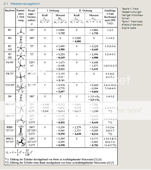
What is the bank angle of the W16 anyway? On the W8 and W12, it's 72°, requiring offset crankpins for even firing and balance shafts for full balancing. The graphic below shows the balancing of some less common cylinder arrangements used in the VW Group.
The driving factor in arriving to the selected layout and firing order of the W16 was to give the best compromise of balancing and more importantly, torsional vibration modes. As cylinder counts increase and crankshafts become longer and less stiff (offset crankpins, little overlap between throws and mains journals due to relatively long stroke), critical torsional vibration modes become more of an issue.
#3
Posted 25 April 2008 - 12:11
Thanks for the table its been really helpful
There is a 90 degree angle between the two banks of the W16 engine so the crank pins are not offset. Also because of the W16 layout isn't the crank equal to or shorter than that of a V12 engine?
For the W12 I can see the following figures 120/22/12/0.075. Are the first two figures the angle between the crankpins, the third the offset/splay angle and the last (0.075)?
What does Kraft mean?
After thinking about an alternative W16 crank I think that my initial idea may cause slight end-to-end vibration, as the the two outer cylinders (on each end of the bank) are not in the same position. For the W16 a symmetrical 'X' dual flat plane layout could be used (withstanding your comments about rigidty of course).
Here is a good animation of the W8 if you haven't already seen it:
W8 3D Engine Animation
I another thread Greg Locock mentioned splitting a V10 into 2 V5 with a flywheel inbetween to increase the revs of a high capacity V10. I wouder if such an idea could be used on the W16 to reduce the loads on a single crank?
Cheers
Obi
#4
Posted 25 April 2008 - 15:42
"Kraft" means force.
Any crank layout could be conceivably employed, but any arrangement that gives anything but a 45° interval in a 16-cylinder engine -- like your dual-flat "X" proposal (i.e. 90° interval) without offset crankpins -- will be odd-firing.
#5
Posted 25 April 2008 - 17:55
Originally posted by TDIMeister
I also tried to figure out what the value of 0.075 means. At first, I thought it was the bank offset distance from the centerline, but even if quoted in metres, 7.5 cm is an awful lot. I honestly don't know. Maybe I should read the paper from which the chart came in closer detail...
"Kraft" means force.
Any crank layout could be conceivably employed, but any arrangement that gives anything but a 45° interval in a 16-cylinder engine -- like your dual-flat "X" proposal (i.e. 90° interval) without offset crankpins -- will be odd-firing.
Thanks TDIMeister.
Do you have a translation for *1} and *2} at the bottom of the page?
BTW, both of the crank examples I gave will fire every 45 degrees without needing any crank offset/splay.
Looking at the crank from head-on as in the diagrams you posted, my first idea would look most like the 75 degree V8 accept there would be no angle between 5 & 1 (my 1 & 2), 6 & 2 (my 3 & 4), 8 & 4 (my 5 & 6) and 7 & 3 (my 7 & 8). The angle between 1/2 and 3/4 is 60 degrees, the angle between 3/4 and 5/6 is 120 degrees, the angle between 5/6 and 7/8 is 60 degrees. That then leaves 60 degrees between 7/8 and 1/2.
The crank would look like this Apache tail rotor: Crank Angle Shape
Having looked at things further I discovered that VW treat each main bank as a normal bank in a standard V engine. In the case of the W16 each main bank contains 8 cylinders as we know, and as we know they are not inline as in the bank of a V16 but staggered. Even though the cylinders are staggered VW matched the absolute first and last cylinder in each main bank to each others vertical position, despite there being a 15 degree angle between them.
I think in my first example there would be slight end-to-end vibration because whereas VW will match the first and last cylinder in each main bank (lets call them 1 & 8 for one bank and 9 & 16 for the other), my example treats the engine as two V8 engines, the outside cylinders of one main bank match the inside cylinders of the other main bank. Because of this cylinders 1 & 7 then 2 & 8 in one bank will match and 9 & 15 then 10 & 16 in the other bank will match.
Because the W16 has its main banks set 90 degrees apart I would think an 'X' crank with 90 degrees between each pair of arms (1/2 - 90 degrees, 3/4 - 90 degrees, 5/6 - 90 degrees, 7/8 - 90 degrees) could be used, with cylinders at the end of each bank matching.
Cheers
Obi
#6
Posted 25 April 2008 - 18:13
#7
Posted 25 April 2008 - 19:30
I'm sorry you're correct, ignore what I wrote about the 90 degree crank. The crank should be the same as the one I specified earlier like the Apache tailrotor. Also when I mentioned VW matching the cylinders end-to-end, I was talking about the W8 and W12 engines, the description of the W16 being matched end-to-end is if an Apache tailrotor type crank is used.
Rewriting my first post about cylinder arrangement:
Arms 1 and 2 will correspond with cylinders 1/8 and 9/16 respectively and is at 120 degree to arms 7 & 8.
Arms 3 and 4 will correspond with cylinders 2/7 and 10/15 respectively and is at 60 degrees to arms 1 & 2.
Arms 5 and 6 will correspond with cylinders 3/6 and 11/14 respectively and is at 120 degrees to arms 3 & 4.
Arms 7 and 8 will correspond with cylinders 4/5 and 12/13 respectively and is at 60 degrees to arms 5 & 6
I hope that makes things clearer.
Currently I don't have the facility to store data online so it would be difficult to post a diagram. If you still find my descriptions a little confusing however, I will try and sort something out.
Cheers
Obi
#8
Posted 28 April 2008 - 02:18
Apologies again but my last post was wrong, hopefully I'll get it right this time.
Second rewriting of my first post about cylinder arrangement :
Arms 1 and 2 will correspond with cylinders 1/8 and 9/16 respectively and is at 135 degree to arms 7 & 8.
Arms 3 and 4 will correspond with cylinders 2/7 and 10/15 respectively and is at 45 degrees to arms 1 & 2.
Arms 5 and 6 will correspond with cylinders 3/6 and 11/14 respectively and is at 135 degrees to arms 3 & 4.
Arms 7 and 8 will correspond with cylinders 4/5 and 12/13 respectively and is at 45 degrees to arms 5 & 6.
The even numbered arms will be offset from their respective odd numbered arms by +15 degrees.
Arm 1 = 0 degrees ----- Arm 2 = 15 degrees
Arm 3 = 45 degrees ---- Arm 4 = 60 degrees
Arm 5 = 180 degrees --- Arm 6 = 195 degrees
Arm 7 = 225 degrees --- Arm 8 = 240 degrees
So the effect of this arrangement should be a W16 engine with the characteristics of dual Flat-Plane V8 engines pieced together.
Obi
#9
Posted 28 December 2008 - 02:51
Looking at the diagram of the VW cranks posted, we can see that the WR12 crank is like a V12 crank but with half of the shaft twisted by 15 degrees, as well as the arms being split by 12 degrees. The crank I'm proposing will be like an Apache tail rotor (not a truely symmetrical cross shape), but with the same 15 degree crankshaft twist I mentioned above with the WR12.
Arms 1 & 2 are 15 degrees apart and correspond with cylinders 1-9 and 8-16 respectively.
Arms 3 & 4 are 15 degrees apart and correspond with cylinders 2-10 and 7-15 respectively.
Arms 5 & 6 are 15 degrees apart and correspond with cylinders 3-11 and 6-14 respectively.
Arms 7 & 8 are 15 degrees apart and correspond with cylinders 4-12 and 5-13 respectively.
The even numbered arms will be offset from their respective odd numbered arms by +15 degrees.
Arm 1 = 0 degrees -- Arm 2 = 15 degrees
Arm 3 = 45 degrees -- Arm 4 = 60 degrees
Arm 5 = 180 degrees -- Arm 6 = 195 degrees
Arm 7 = 225 degrees -- Arm 8 = 240 degrees
Even though cylinders at both ends of a bank will be at the same height (as in a V12 or flat-plane V8), they will be travelling in different directions due to the 15 degree angle between them. I'm wondering if this coupled with the fact that the respective arms are 15 degrees apart (so the the crank by 'itself' will be unbalanced end to end, unlike a V12 in which half of the 6 arms have identical angles), will lead to an engine with end to end vibrations?
Obi