Jump to content


Photo

Clever ...


  • Please log in to reply
88 replies to this topic

#1 cheapracer

cheapracer
  • Member

  • 10,388 posts
  • Joined: May 07

Posted 10 December 2011 - 16:28

Clever, I love clever and can look at clever things all day long.

Here is something clever, a way to mount your much shorter upper control arms in an extremely neat fashion (at a quick glance it just looks like a big upper control arm) that's also very economical engineering wise ie strong and light. Obviously a great place to mount your outboard shocks as well .. that upper compression load rod could of course go underneath in tension if required (bodywork clearance etc)....

Posted Image

If you have something clever to show .......

Edited by cheapracer, 10 December 2011 - 16:32.


Advertisement

#2 MatsNorway

MatsNorway
  • Member

  • 2,822 posts
  • Joined: December 09

Posted 10 December 2011 - 17:06

Since we are looking at small racers i might as well dump it here..
http://speedhunters....ini-can-am.aspx

Edited by MatsNorway, 10 December 2011 - 17:13.


#3 rachael

rachael
  • Member

  • 118 posts
  • Joined: October 10

Posted 10 December 2011 - 21:18

I disagree about the adequacy of the shock mount - looks far too flexible, but the upper arm mounting is reasonable.

This gets my vote for clever; negative stiffness


#4 Tony Matthews

Tony Matthews
  • Member

  • 17,519 posts
  • Joined: September 08

Posted 10 December 2011 - 21:31

I disagree about the adequacy of the shock mount - looks far too flexible, but the upper arm mounting is reasonable.

Even with the strut going from just inboard of the top damper mount to the top chassis rail? It looks quite good to me - where do you think the flexibility would reveal itself?

#5 rachael

rachael
  • Member

  • 118 posts
  • Joined: October 10

Posted 10 December 2011 - 21:40

Even with the strut going from just inboard of the top damper mount to the top chassis rail? It looks quite good to me - where do you think the flexibility would reveal itself?


Hi Tony! the strut looks like it's at an oblique angle and is mounted to an unsupported span of chassis rail - really needs a brace spanning the chassis between the two struts imo.

#6 Tony Matthews

Tony Matthews
  • Member

  • 17,519 posts
  • Joined: September 08

Posted 10 December 2011 - 22:05

Nice to have you back Rachael! I know what you mean, the photograph doesn't give quite enough info., but those struts seem to join the top rails at the same point(ish) as the braces to the instrument roll hoop. The rack is in an interesting place, either the u/j in the steering column is working at quite an angle, or the wheel is mounted like a dodgem car!

#7 mariner

mariner
  • Member

  • 2,334 posts
  • Joined: January 07

Posted 10 December 2011 - 22:35

I cant find a pic easly but although it was no great success the Lotus 70 F5000 car had a clever front suspension whereby the top of the coil spring/damper was mounted in a cup of matching pressed steel halves which were attached to the top wishbone mount.

This had two benefits

1) - the spring/damper unit could be longer and therefore possibly better stroke options because the top mount was well above the top wishbone/ chassis line.

2) Only the top wishbone chassis mounts are required and all the loads go into them so avoiding loading chassis tubes halfway along as in some many designs

I will try to find a drawing if anyone is interested

Edited by mariner, 11 December 2011 - 01:47.


#8 Lee Nicolle

Lee Nicolle
  • Member

  • 11,064 posts
  • Joined: July 08

Posted 11 December 2011 - 02:05

To me there is several faults. A the top wishbone is quite short, may or not be an issue. B Those rod ends are mounted flat, they should be at 90 eg to what they are.The suspension loads are trying to pull the ball out of the socket!! And have very little travel in comparison. C as was pointed out another brace between the top pick ups would be nice.
Though its plus is that having the shock and spring out near the wheel like that a very soft spring, read less unsprung weight, and easier to fine tune too I would imagine.

#9 Lee Nicolle

Lee Nicolle
  • Member

  • 11,064 posts
  • Joined: July 08

Posted 11 December 2011 - 02:05

To me there is several faults. A the top wishbone is quite short, may or not be an issue. B Those rod ends are mounted flat, they should be at 90 eg to what they are.The suspension loads are trying to pull the ball out of the socket!! And have very little travel in comparison. C as was pointed out another brace between the top pick ups would be nice.
Though its plus is that having the shock and spring out near the wheel like that a very soft spring, read less unsprung weight, and easier to fine tune too I would imagine.

#10 cheapracer

cheapracer
  • Member

  • 10,388 posts
  • Joined: May 07

Posted 11 December 2011 - 05:03

Lotus 70 F5000

I will try to find a drawing if anyone is interested


http://carblueprints...-f5000-1969.gif
http://www.oldracing...lv-20000721.jpg

Hi Tony! the strut looks like it's at an oblique angle and is mounted to an unsupported span of chassis rail - really needs a brace spanning the chassis between the two struts imo.


Maybe the picture doesn't show it so well but the loads go up into the front rollbar support which may look flat in that picture but are not and is well braced side to side.

I would do the bracing/load feeds in and around the footwell differently though.

To me there is several faults. A the top wishbone is quite short, may or not be an issue. B Those rod ends are mounted flat, they should be at 90 eg to what they are.The suspension loads are trying to pull the ball out of the socket!! And have very little travel in comparison.

Though its plus is that having the shock and spring out near the wheel like that a very soft spring, read less unsprung weight, and easier to fine tune too I would imagine.


A. It's not short but that's relevant to other things, roll stiffness, tyre type etc so a determination can not be made by looks alone - the car was successful in it's class (American DSR).

B. The top arm has none of those loads you mention but the lower inner joints do and sure they could be turned 90 degrees.

Mats, http://dsr.racer.net/ I spend hours here sometimes, click on the "chassis" link on the left.

I just posted this as a generally better way to do it rather than specific to the car itself and a few of us here have seen that mounting top arms is often poorly done and ugly to get that outboard mounting position.

I hope some might post other clever thing they see over time, not specific to suspension just specific to "clever"!


#11 Woody3says

Woody3says
  • Member

  • 426 posts
  • Joined: January 11

Posted 11 December 2011 - 05:07

Hey cheapracer, any thoughts on working this into your car?

#12 gruntguru

gruntguru
  • Member

  • 7,642 posts
  • Joined: January 09

Posted 11 December 2011 - 05:11

Hi Tony! the strut looks like it's at an oblique angle and is mounted to an unsupported span of chassis rail - really needs a brace spanning the chassis between the two struts imo.

In fact none of the 3 members locating the shock mount is feeding into a laterally supported node.

#13 cheapracer

cheapracer
  • Member

  • 10,388 posts
  • Joined: May 07

Posted 11 December 2011 - 05:22

Hey cheapracer, any thoughts on working this into your car?


Not at all, but I still think it's a good idea.


#14 MatsNorway

MatsNorway
  • Member

  • 2,822 posts
  • Joined: December 09

Posted 11 December 2011 - 09:56

To me there is several faults. A the top wishbone is quite short, may or not be an issue.


Could be wish for Camber lift. due to experience.. or could be a sideeffect with little issues as you say.

#15 carlt

carlt
  • Member

  • 4,169 posts
  • Joined: June 09

Posted 11 December 2011 - 18:46

Chapman certainly wouldn't have been impressed - far too many chassis tubes doing what could adequately be done with fewer

#16 MatsNorway

MatsNorway
  • Member

  • 2,822 posts
  • Joined: December 09

Posted 11 December 2011 - 20:06

Clever pump. perhaps.
http://www.youtube.c...feature=related

#17 Kelpiecross

Kelpiecross
  • Member

  • 1,730 posts
  • Joined: October 10

Posted 13 December 2011 - 05:06

I hope some might post other clever thing they see over time, not specific to suspension just specific to "clever"!
[/quote]

My nomination for "clever" has to be the Helical Camshaft. This is probably only relevant to people who have had a long-term interest in the search for a method of varying the duration of a camshaft (like me) - but I find this gadget amazing. For something like this to suddenly appear after maybe 80 years of trying by big companies and individual engineers and inventors is almost unheard of.

On the subject of Colin Chapman and "clever" - I was reminded recently just how clever Chapman was by the "Lotus" episode of "Design for Victory". It is amazing just how many breakthroughs he came up with.
On the downside - he was inclined to overdo things a little and be a little flimsy in his search for lightness and simplicity. The original rear, upper inner suspension mounting points on the Lotus 49 - unbelievably flimsy.

#18 cheapracer

cheapracer
  • Member

  • 10,388 posts
  • Joined: May 07

Posted 13 December 2011 - 05:19

Chapman certainly wouldn't have been impressed - far too many chassis tubes doing what could adequately be done with fewer


The Lotus 7 chassis has been referred to as being made from spaghetti and has been developed from less than 1000 ftlbs/deg to well over 3000 ftlbs/deg with very little addition of weight in Locost form.

People seem to forget that Chapman made some pretty awful cars.


#19 Tom17

Tom17
  • Member

  • 36 posts
  • Joined: December 05

Posted 22 December 2011 - 18:18

How about moving that horizontal tube that passes under the two diagonal tubes that meet at the front roll bar? It doesn't seem to be doing a lot where it is so would be more useful further toward the front where the two diagonals meet the side tubes and pick up on that compression rod. Yes?

Advertisement

#20 Fat Boy

Fat Boy
  • Member

  • 2,594 posts
  • Joined: January 04

Posted 22 December 2011 - 19:38

Just say 'no' to feeding loads into the middle of a tube.

#21 carlt

carlt
  • Member

  • 4,169 posts
  • Joined: June 09

Posted 22 December 2011 - 19:44

The Lotus 7 chassis has been referred to as being made from spaghetti and has been developed from less than 1000 ftlbs/deg to well over 3000 ftlbs/deg with very little addition of weight in Locost form.

People seem to forget that Chapman made some pretty awful cars.


'Adequately' was the key word

no need for 3000ftlb/deg when the power plant develops 50hp and the performance tyres of the day were 550x15 crossply


The Lotus 7 with a very few added thin guage tubes and bonded alloy panels is still the chassis to beat
not bad for a cheap 50 year old design ?

yes he made some pretty awful cars - when you've made that many new designs consistently over a long period of time then make the same judgment
:)

#22 24gerrard

24gerrard
  • Member

  • 2,008 posts
  • Joined: March 11

Posted 22 December 2011 - 21:40

Colin once said of F1 car. If they fell apart just after going over the finish line they were optimum.

#23 cheapracer

cheapracer
  • Member

  • 10,388 posts
  • Joined: May 07

Posted 23 December 2011 - 07:10

yes he made some pretty awful cars - when you've made that many new designs consistently over a long period of time then make the same judgment
:)


I can make a superior car to Chapman any day of he week, different times, different tools.

Oh and I start in a couple of months (relative to production, not "one offs") so your chance to judge me is close :)


#24 carlt

carlt
  • Member

  • 4,169 posts
  • Joined: June 09

Posted 23 December 2011 - 09:09

I can make a superior car to Chapman any day of he week, different times, different tools.

Oh and I start in a couple of months (relative to production, not "one offs") so your chance to judge me is close :)


Lotus Mark I (1948): Austin 7 based car
Lotus Mark II (1949–1950): Ford-powered trials car
Lotus Mark III (1951): 750 cc formula car
Lotus Mark IV (1952): Trials car
Lotus Mark V (1952 2): 750 cc formula car—never built
Lotus Mark VI (1953–1955): The first "production" racer—about 100 built
Lotus Seven (1957–1970): Classic open sports car, a minimalist machine designed to manoeuvre a racing circuit and nothing else. The rights to the Seven were sold in 1973 to Caterham Cars, who continue to produce it today. Updated versions of this 1957 design are also produced by other speciality firms, including Westfield Sportscars and Donkervoort. Originally the number seven was applied to a Riley-powered Formula 2 car, but the vehicle was never completed in its original form, finally emerging instead as the Clairmonte Special, a two-seat sports car powered by a Lea-Francis engine.
Lotus Mark VIII (1954): sports racer
Lotus Mark IX (1955): sports racer, based on Eight
Lotus Mark X (1955): sports racer, a more powerful Eight
Lotus Eleven (1956–1957): sports racer
Lotus 12 (1956–1957): Formula Two and Formula One racecar
Lotus 13: Designation not used
Lotus 14 (1957–1963): First production street car—the Elite
Lotus 15 (1958): Sports racer—successor to the Eleven
Lotus 16 (1958–1959): F1/F2 car based on the Twelve
Lotus 17 (1959): Sports racer update of the 15—not successful
Lotus 18 (1960–1961): First mid-engined Lotus single seater—Formula Junior/F2/F1
Lotus 19 (1960–1962): Mid-engined sports racer—"Monte Carlo"
Lotus 20 (1961): Formula Junior
Lotus 21 (1961): Formula One
Lotus 22 (1962–1965): Formula Junior/F3
Lotus 23 (1962–1966): Small displacement mid-engined sports racer
Lotus 24 (1962): Formula One
Lotus 25 (1962–1964): Formula One World Champion
Lotus 26 (1962–1971): Production street sports car—the original Elan.
Lotus 27 (1963): Formula Junior
Lotus 28 (1963–1966): Lotus version of the Ford Cortina street/racer
Lotus 29 (1963): Indy car—Ford stock block
Lotus 30 (1964): Large displacement sports racer (Ford V8)
Lotus 31 (1964–1966): Formula Three space frame racer
Lotus 32 (1964–1965): Monocoque F2 and Tasman Cup racer
Lotus 33 (1964–1965): Formula One World Champion
Lotus 34 (1964): Indy car—DOHC Ford
Lotus 35 (1965): F2/F3/FB
Lotus 36 (1965–1968): Fixed Head Coupe version of the original Elan, so called perhaps to distinguish it from the Type 26 Elan which could be fitted with a removable hard top)
Lotus 38 (1965): Indy winning mid-engined car
Lotus 39 (1965–1966): Tasman Cup formula car
Lotus 40 (1965): Improved(?) version of the 30
Lotus 41 (1965–1968): Formula Three, Formula Two, Formula B
Lotus 42 (1967): Indy car—raced with Ford V8
Lotus 43 (1966): Formula One
Lotus 44 (1967): Formula Two
Lotus 45 (1966–1974): Convertible (Drop Head Coupe), a version of the original Elan with a revised body style, most notable for its permanent side window frames.
Lotus 46 (1966–1968): Original Renault-engined Europa
Lotus 47 (1966–1970): Racing version of Europa
Lotus 48 (1967): Formula Two
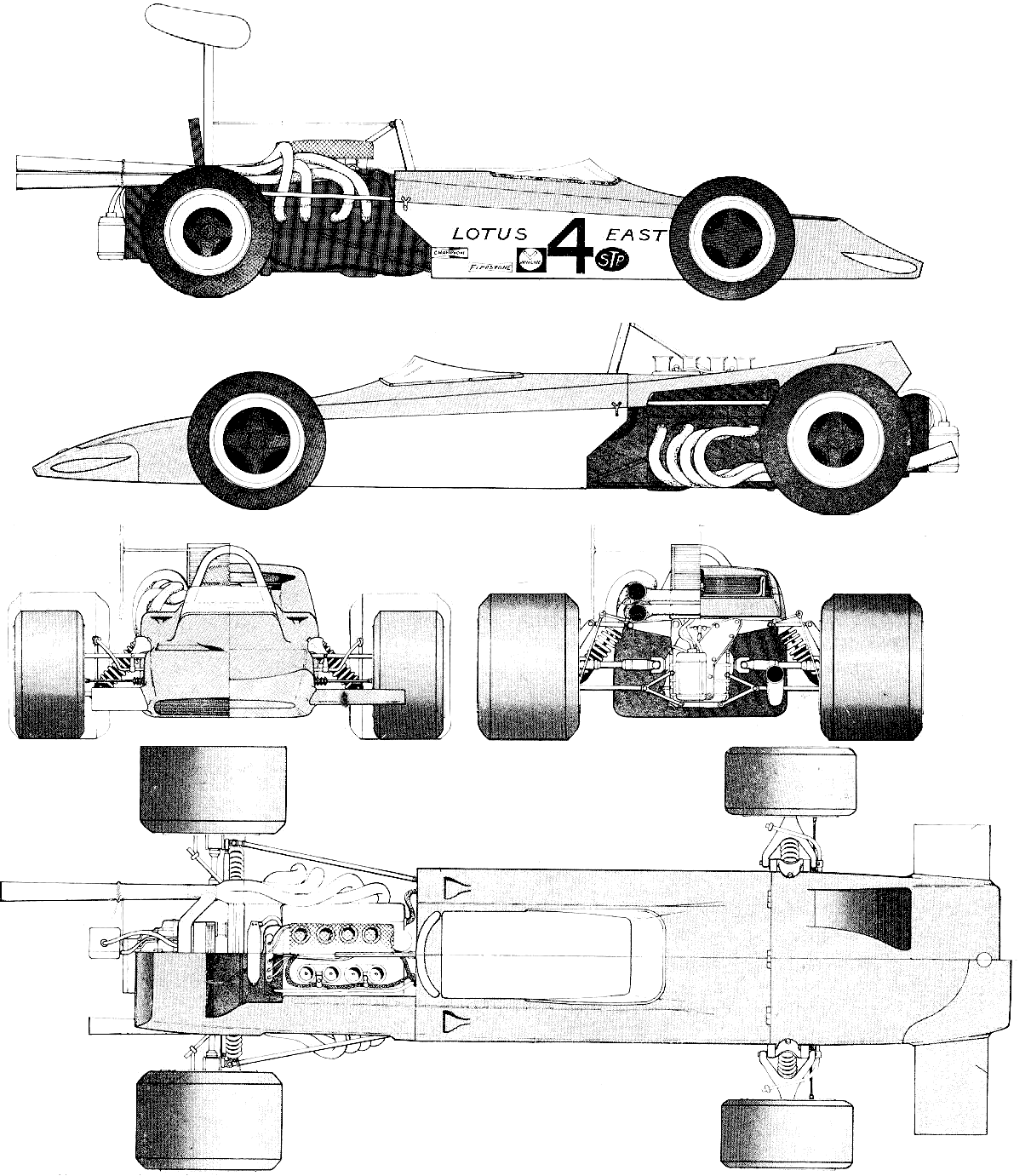
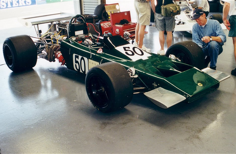
Lotus 49 (1967–1969): Formula One World Champion
Lotus 50 (1967–1974): Four-seat "Elan +2" production car
Lotus 51 (1967–1969): Formula Ford
Lotus 52 (1968): Prototype "Europa" twincam
Lotus 53 (1968): Small displacement sports racer—never built
Lotus 54 (1968–1970): Series 2 "Europa" production car.
Lotus 55 (1968): F3
Lotus 56 (1968–1971): Indy turbine wedge/F1 turbine (56B)
Lotus 57 (1968): F2 design study
Lotus 58 (1968): F1 design study
Lotus 59 (1969–1970): F2/F3/Formula Ford
Lotus 60 (1970–1973): Greatly modified version of the Seven—AKA Seven S4
Lotus 61 (1969): Formula Ford wedge
Lotus 62 (1969): prototype Europa racer
Lotus 63 (1969): 4-wheel drive F1
Lotus 64 (1969): 4-wheel drive Indy cars—did not compete
Lotus 65 (1969–1971): "Federalized" Europa S2
Lotus 66: designation not used
Lotus 67 (1970): Proposed Tasman Cup car—never built
Lotus 68 (1969): F5000 prototype
Lotus 69 (1970): F2/F3/Formula Ford
Lotus 70 (1970): F5000/Formula A
Lotus 71: Undisclosed design study
Lotus 72 (1970–1972): Formula One World Champion
Lotus 73 (1972–1973): F3
Lotus 74 (1971–1975): Europa Twin Cam production cars
Lotus 75 (1974–1982): Luxury 4-seat GT—"Elite II"
Lotus 76 (1975–1982): Fastback version of Elite II—"Éclat S1"—also 1974 F1
Lotus 77 (1976): F1
Lotus 78 (1977–1978): F1 ground effects car
Lotus 79 (1978–1979): Formula One World Champion—also street GT "Esprit" (1975–1980)
Lotus 80 (1979): F1
Lotus 81 (1980–1981): F1—designation also used for Sunbeam Talbot rally car
Lotus 82 (1982–1987): Turbo Esprit street GT car
Lotus 83 (1980): Elite series 2
Lotus 84 (1980–1982): Éclat series 2
Lotus 85 (1980–1987): Esprit series 3
Lotus 86 (1980–1983): F1 dual chassis—never raced
Lotus 87 (1980–1982): F1
Lotus 88 (1981): F1 dual chassis car—banned
Lotus 89 (1982–1992): Lotus Excel GT—re-engineered Éclat


Then we'll judge you on the 'pretty awful" car you made

#25 24gerrard

24gerrard
  • Member

  • 2,008 posts
  • Joined: March 11

Posted 23 December 2011 - 09:34

Hes Australian, dont knock it, they can build darn good cars.
At least he is abroad and away from the sheep so give him credit.

#26 cheapracer

cheapracer
  • Member

  • 10,388 posts
  • Joined: May 07

Posted 23 December 2011 - 10:23

Then we'll judge you on the 'pretty awful" car you made


I'm lost, I have no idea what your point is :confused:


#27 carlt

carlt
  • Member

  • 4,169 posts
  • Joined: June 09

Posted 23 December 2011 - 17:26

People seem to forget that Chapman made some pretty awful cars.


just saying in context -- on the quantity and rapidity of design [and some pretty groundbreaking ideas as well]

a few awful ones are almost inevitable.

when you personally have achieved the equivalent we will no doubt pick out your 'awful' cars ? :)

I thought you Aussies had thick skins ? :)

#28 cheapracer

cheapracer
  • Member

  • 10,388 posts
  • Joined: May 07

Posted 23 December 2011 - 18:25

when you personally have achieved the equivalent we will no doubt pick out your 'awful' cars ? :)

I thought you Aussies had thick skins ? :)


Well I do have thick skin but I need to understand what it is I'm shrugging off :cool:

I nor anybody else has to achieve his equivalent to quote history, what is seen can't be unseen and anyway as I said, I (and many others) can do better simply because of the different times that we live in, it's actually difficult to make a really bad car nowadays.

FWIW, no one has ever released a car with the front and rear suspension that I have designed and am using, it's a first so you will have a chance to judge me very shortly ....it may be awful :lol:

BTW, the current Locost and current Caterham car's FEA developed chassis has no relationship to the Lotus 7 Mark 1 through Mark 4 other than obviously being vaguely similar having to have tubes in similar areas to form the same basic shape.


#29 Wolf

Wolf
  • Member

  • 7,883 posts
  • Joined: June 00

Posted 23 December 2011 - 18:58

My memory may have gone, but if you're still talking about Lotus 7, might I just add that ISTR that one of those little cars had abut an inch cut out from midlle section (lengthwise) and was welded back together in order to comply with then current F1 rules and was actually raced in non-championship F1 race*? Not bad for something made of spaghetti. (And might I add that back in the day, F1 engines usualy had over 140BHP)

* can't give you details off top of my head- but I think it was one of South African races in 1.5l era (I would think '62 if I had to take a guess, Natal GP also seems to ring a bell)

#30 cheapracer

cheapracer
  • Member

  • 10,388 posts
  • Joined: May 07

Posted 23 December 2011 - 19:35

* can't give you details off top of my head- but I think it was one of South African races in 1.5l era (I would think '62 if I had to take a guess, Natal GP also seems to ring a bell)


Wow, Wolf, blast from the past! Thought you were long gone, hope things are all good.

http://www.theracedr...f1-nothing-new/

Posted Image

Edited by cheapracer, 23 December 2011 - 19:37.


#31 carlt

carlt
  • Member

  • 4,169 posts
  • Joined: June 09

Posted 23 December 2011 - 20:25

BTW, the current Locost and current Caterham car's FEA developed chassis has no relationship to the Lotus 7 Mark 1 through Mark 4 other than obviously being vaguely similar having to have tubes in similar areas to form the same basic shape.


The Lotus 7 series 1 is a very good chassis , a very elegant design - has there been any torsional tests done on it ? [ it is essentially a Lotus 11 with revised suspension pick up points suitable for road car ground clearance]

the series 2 is an inferior chassis , many of the tubes considered non essential for a road car chassis were deleted by Lotus from the production run and the internal cockpit panelling [steel lamiplate] was used as a substitute - this is usually removed from competition cars for 'weight saving' - most people not realising that this removes all the structural triangulation from the chassis sides - I think this is the spaghetti chassis you refer to

Edited by carlt, 23 December 2011 - 20:32.


#32 desmo

desmo
  • Tech Forum Host

  • 29,523 posts
  • Joined: January 00

Posted 23 December 2011 - 21:31

Nice to see you've dropped in again Wolf.

#33 cheapracer

cheapracer
  • Member

  • 10,388 posts
  • Joined: May 07

Posted 24 December 2011 - 06:33

has there been any torsional tests done on it ?


Posted Image

Posted Image

Notice how many boxes are unbraced/no triangulation and poor use of node intersection, even for 1950's. I believe it's under 700 ft/lbs per degree. Even with barely 50 hp and skinny conventionals you would notice that.

Edited by cheapracer, 24 December 2011 - 07:01.


#34 Greg Locock

Greg Locock
  • Member

  • 6,364 posts
  • Joined: March 03

Posted 24 December 2011 - 07:35

Presumably there's nothing in the rules against triangulating the frame. So which win races, the lighter ones with the original frames, or the heavier triangulated ones? Given that some quite serious machinery comes in at 1500-4000 lb ft/deg, is 700 so unreasonable for a 50 hp car?


#35 24gerrard

24gerrard
  • Member

  • 2,008 posts
  • Joined: March 11

Posted 24 December 2011 - 09:50

Also how much flex improves handling, it does in karts and scale model cars.
At this size and weight there is a cross over.

#36 cheapracer

cheapracer
  • Member

  • 10,388 posts
  • Joined: May 07

Posted 24 December 2011 - 09:58

Presumably there's nothing in the rules against triangulating the frame. So which win races, the lighter ones with the original frames, or the heavier triangulated ones? Given that some quite serious machinery comes in at 1500-4000 lb ft/deg, is 700 so unreasonable for a 50 hp car?


I have to presume your refering to those older days where tyre's performance were below the chassis performance.

Mind you it's come the complete circle almost, road surfaces and tyres are so good now they hide chassis defects to a point.


Also how much flex improves handling, it does in karts and scale model cars.


Because they have no suspension.


#37 carlt

carlt
  • Member

  • 4,169 posts
  • Joined: June 09

Posted 24 December 2011 - 11:27

Posted Image

Posted Image

Notice how many boxes are unbraced/no triangulation and poor use of node intersection, even for 1950's. I believe it's under 700 ft/lbs per degree. Even with barely 50 hp and skinny conventionals you would notice that.


you'll find, if you care to, that that is not a series 1 Lotus 7

also the alloy transmission tunnel was structural andfed into the seat back [ which was fully triangulated in the series1 [there were a few built with dedion suspension - the diff being mounted on the seat back ]

Edited by carlt, 24 December 2011 - 11:31.


#38 24gerrard

24gerrard
  • Member

  • 2,008 posts
  • Joined: March 11

Posted 24 December 2011 - 12:58

QUOTE (24gerrard @ Dec 24 2011, 17:50)
Also how much flex improves handling, it does in karts and scale model cars.


Cheapracer: Because they have no suspension.


1:10 scale cars have very sofisticated suspension but also take chassis flex into account.
Mainly because of the spool diffs and 4wd used.

Karts only have no suspension because of regulations.
My suggested design for an 'electric' kart/short circuit car has both.

Edited by 24gerrard, 24 December 2011 - 12:59.


#39 mariner

mariner
  • Member

  • 2,334 posts
  • Joined: January 07

Posted 24 December 2011 - 14:11

If the frame pics above are meant to represent the Lotus 7 as orignally made then they are not very representative because they miss out the rear bulkhead, floor and prop. shaft panelling, all of which contributed to the torsional stiffness.

I agree that the older cars needed less rigidity as tyres gave less grip but then surely that shows good design as no material was wasted on rigidity that was not needed.

I won't get into long arguments about how good or ( as Cheapy sees it, bad) Chapman's cars were, only to say he both innovated AND won, a very rare thing indeed in motor racing history. I love the Chapparal's for their innovation etc. but in reality they were not very successful in race wins , wonderful though they are.


In terms of how rigid the Lotus 7 actually was I would suggest that if somebody has both the Costin and Phiipps book AND acess to FEA then if you go to the appendices in Costin and Phipps there is a full stress analysis of the Lotus 9( it may be the 8) in appendix 1, page 109. All the weights, tube sizes and loads are laid out in detail so I would think that with todays FEA tools it would be easy to work out the torsoinal rigidity. Not exactly the 7 but very similar. Again the lack of contribution from panelling will be missing.

So if everybody else is asleep after Christmas lunch that is a way to occupy the rest of your day - Happy Christmas to all!

Advertisement

#40 Tony Matthews

Tony Matthews
  • Member

  • 17,519 posts
  • Joined: September 08

Posted 24 December 2011 - 15:13

So if everybody else is asleep after Christmas lunch that is a way to occupy the rest of your day - Happy Christmas to all!

Happy Christmas to you too, mariner, and let's hope that the New Year will see an absence of these stupid arguments about who killed who with what and I don't have to look at whole pages of 'ignore' signs...

#41 carlt

carlt
  • Member

  • 4,169 posts
  • Joined: June 09

Posted 24 December 2011 - 15:36

the best pic I could find at short notice
http://www.andywilts...er_products.htm

incidentally the engine bay floor and the rear of the cockpit floor was fully paneled on the series 1 contributing hugely to torsional strength

both dropped from series 2 production as considered unnecessary for a road car [ cheapyness of production was priority :) ]

contrary to meester cheapies analysis I would suggest there is very little difference between the series 1 and the Caterham 7 [ until the recent fully automated metric chassis ]

merry crassmess

seasons greatings

Carl

#42 carlt

carlt
  • Member

  • 4,169 posts
  • Joined: June 09

Posted 24 December 2011 - 16:00

Something that might interest you over the holiday Cheapy [ looks a bit similar in concept to yours ? ]

http://www.ten-tenth...mp;d=1273135257

this is the worlds first production multi-tubular spaceframe chassis

The Buckler MK5 chassis [ beam axles both ends :) ]

http://www.bucklercars.com/

I am Trialing one MK5 and currently building another with a few developments, supercharged sidevalve ! [ and building a Lotus 7 series 1 :) ]

Edited by carlt, 24 December 2011 - 16:03.


#43 cheapracer

cheapracer
  • Member

  • 10,388 posts
  • Joined: May 07

Posted 24 December 2011 - 16:46

Chapman's cars were ( as Cheapy sees it, bad)


I said he made some awful cars ......


and the Caterham 7 [ until the recent fully automated metric chassis ]


Maybe you mistook my use of the word "current" for something else being Xmas and all? - the sort mixed with raisins?


Something that might interest you over the holiday Cheapy [ looks a bit similar in concept to yours ? ]


On a moonless night wearing sunglasses in a thick fog, sure, can't tell the difference...


this is the worlds first production multi-tubular spaceframe chassis

The Buckler MK5 chassis [ beam axles both ends :) ]


Saying anything is a first in the automotive world especially Post War I have found to be a very shaky thing to do. It may have beam axles both end and was in those years a better option if well done, but I doubt bear any relationship to my setup.


I am Trialing one MK5 and currently building another with a few developments, supercharged sidevalve ! [ and building a Lotus 7 series 1 :) ]


Would love to see pictures and details .. :up:

Merry Xmas to one and all :wave: - remember it's just a forum, words on a screen and not important in the greater scheme of things ;)

Edited by cheapracer, 24 December 2011 - 16:47.


#44 carlt

carlt
  • Member

  • 4,169 posts
  • Joined: June 09

Posted 24 December 2011 - 17:55

[ looks a bit similar in concept to yours ? ]

http://www.ten-tenth...mp;d=1273135257


Concept - meaning the double beam lozenge chassis sides + cheap, readily available production car components [ Buckler utilised the whole of the E92A Pop mechanicals ]

#45 carlt

carlt
  • Member

  • 4,169 posts
  • Joined: June 09

Posted 24 December 2011 - 17:57

Would love to see pictures and details .. :up:


sorry - too many secret competitive tweeks , don't know who's looking :lol:

#46 24gerrard

24gerrard
  • Member

  • 2,008 posts
  • Joined: March 11

Posted 24 December 2011 - 18:24

Concept - meaning the double beam lozenge chassis sides + cheap, readily available production car components [ Buckler utilised the whole of the E92A Pop mechanicals ]


Remember it well. got fed up with the half shaft coming out like eyes on stalks.
Swapped it for an early Cooper Porche.
That was a bit like a miniature birdcage Masa.

#47 24gerrard

24gerrard
  • Member

  • 2,008 posts
  • Joined: March 11

Posted 24 December 2011 - 18:26

sorry - too many secret competitive tweeks , don't know who's looking :lol:


Know what you mean could show you mine but would have to shoot you after.

#48 carlt

carlt
  • Member

  • 4,169 posts
  • Joined: June 09

Posted 24 December 2011 - 18:41

could show you mine but would have to shoot you after.


You'd have to shoot me first :lol:

#49 cheapracer

cheapracer
  • Member

  • 10,388 posts
  • Joined: May 07

Posted 24 December 2011 - 19:02

sorry - too many secret competitive tweeks , don't know who's looking :lol:


Posted Image


#50 Wolf

Wolf
  • Member

  • 7,883 posts
  • Joined: June 00

Posted 24 December 2011 - 20:36

Very nice of you to remember me guys (you certainly surprised me in a pleasant way)- glad to be back. :)

I'd like to add, regarding Chapman and stiffnes, is that I was very surprised when I read Costin's remark that Lotus Mk 8 spaceframe* was nearly perfect example of spaceframe in terms of stiffness and lightness (and best up-to-date)... I understand it had stressed floorboard and skin panels, but to me it seemed like half of tubes were missing. :) Those guys had a great 'feel' for the loads and how they were transmitted through chassis- and I'd say the only considerable improvement from those days (in terms of spaceframe construction) would be newer 'version' of gussets.

* in case anyone's interested, I could post a picture

Edited by Wolf, 24 December 2011 - 20:40.