Jump to content


Photo

Spaceframe joints with dissimilar tube sizes


  • Please log in to reply
141 replies to this topic

#1 NeilR

NeilR
  • Member

  • 623 posts
  • Joined: October 09

Posted 01 January 2012 - 10:43

I'm interested to see if any members have seen space frame joint designs that retain the maximum structural performance (stiffness), particularly when the tube sizes are dissimilar e.g. joining a 30mm round tube to the side of a 50mm square tube.
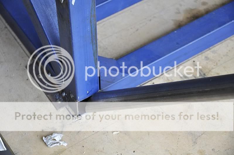
I have been experimenting and have noticed that the contact wall of the larger tube distorts with quite low loads when the smaller tube does not extend to the edges of the square - thus the stiffness of the joint is markedly lower than calculations would suggest.
One of the fixes is to double the local thickness with a welded on plate, internally sleeve the tube with another tube or an internal baffle (perpendicular to the tube) linking all of the walls (assuming you can get access with the welder)...but what other solutions are there?

Edited by NeilR, 01 January 2012 - 10:47.


Advertisement

#2 Greg Locock

Greg Locock
  • Member

  • 6,349 posts
  • Joined: March 03

Posted 01 January 2012 - 10:59

Once upon a time somebody, somewhere, posted a picture of various frame joining details and their joint efficiencies. I can't find it. Google my pretty slaves, google.

#3 NeilR

NeilR
  • Member

  • 623 posts
  • Joined: October 09

Posted 01 January 2012 - 11:15

I've been googling for two days...cue scene from oliver.
BTW I consider myself more of a minion than a slave to all but my wife and cat and then 'staff' seems to be in order.

#4 mariner

mariner
  • Member

  • 2,325 posts
  • Joined: January 07

Posted 01 January 2012 - 17:10

I have no idea on theoretical data but the original Lola 1100 sports racer had as many as" eight tubes having a common apex" ( source Costin and Phipps page 33)

A not too clear photo is here

http://britishraceca...la-Mark1-CA.jpg

Now how many were diferent diameter I don't know but maybe the Nostalgia forum could locate some real detail , or even somebody who has actually worked/repaired the lola 1100.

Anyway I would think that eight tubes with one apex might give some clues.

The other, more theoretical point is that a study showed plates across tube joints increases stiffness ( Milliken p 677).

I would think that brazing, as opposed to welding , might well produce better overall results for lots of different size tubes converging as the braze fllets could produce a nice smooth finish fillet between different sizes which are reasonably close in dimater.

#5 cheapracer

cheapracer
  • Member

  • 10,388 posts
  • Joined: May 07

Posted 01 January 2012 - 17:49

It's very simple, I bore a hole straight through the larger tube, run the smaller tube through and out the other side and weld both sides - I have also seen this a number of times in furniture and other applications.

Or if it's near an open end, bore just one hole and run the tube through to the far wall and weld what you can get too - the "Fable" has a few of those...

#6 Charles E Taylor

Charles E Taylor
  • Member

  • 213 posts
  • Joined: December 07

Posted 01 January 2012 - 18:18

Happy New Year

I do not think This is what you really want, but it provides some good practical advice.

You can find more information here

For a more practical feel, perhaps a visit to an Aircraft Museum might provide a much better insight to best practice.


I hope that helps.


Charlie


#7 desmo

desmo
  • Tech Forum Host

  • 29,343 posts
  • Joined: January 00

Posted 01 January 2012 - 19:59

It's very simple, I bore a hole straight through the larger tube, run the smaller tube through and out the other side and weld both sides - I have also seen this a number of times in furniture and other applications.

Or if it's near an open end, bore just one hole and run the tube through to the far wall and weld what you can get too - the "Fable" has a few of those...


The one example of this joinery I'm familiar with similar to this is a bicycle frame builder who instead of using a conventional chainstay bridge, which is a short tube spanning the two tubular chainstays normally a simple mitred piece brazed into postion, pierced the larger diameter chainstays and ran the chainstay bridge clean through. This was probably done as a simple differentiation move so his frames looked distinvt - as most bicycle frame novelties are - and it looked appealing as one could sight through the pierced chainstays through the tubular bridge but apparently it weakened the chainstays enough to anecdotally cause uncommon failures.

In this case though, the chainstays were highly stressed and the chainstay bridge probably wasn't, being merely a stiffening brace frequently omitted altogether to little or no apparent effect.


#8 Greg Locock

Greg Locock
  • Member

  • 6,349 posts
  • Joined: March 03

Posted 01 January 2012 - 20:55

In a ladder chassis if you run a tube up to a box section, and just do a butt joint, you get about 60% of the ideal torsional stiffness of the joint. If you run the tube through the box and weld it at both ends you get about 90-95%.

Obviously these numbers will vary, depending on gauges and proportions, but those are typical. I sent Neil separately a pretty picture (FEA model) of one joint on the Tbird where an I beam runs up to a box. This is the most important part of the chassis for torsional stiffness. In that case the butt joint was 70% of the ideal stiffness, running it right through gave 95%.

The Corus paper Charles found at http://www.tatasteel.....s 9-08-05.pdf includes guidelines for using an external plate as reinforcement, they call it a saddle, and nomograms for calculating exactly how crappy your plain butt joint will be.

#9 kikiturbo2

kikiturbo2
  • Member

  • 869 posts
  • Joined: December 04

Posted 02 January 2012 - 00:09

I have no idea on theoretical data but the original Lola 1100 sports racer had as many as" eight tubes having a common apex" ( source Costin and Phipps page 33)


seven down, one more to go...

Posted Image


Another option for the 30 mm to 50mm square joint would be an external gusset... like

Posted Image


#10 NeilR

NeilR
  • Member

  • 623 posts
  • Joined: October 09

Posted 02 January 2012 - 04:39

Charles and Greg thanks, that is exactly what I am looking for. I see internal baffles and sleeving is not part of the bracing solution, but then such things can be problematic in an industrial setting.

#11 cheapracer

cheapracer
  • Member

  • 10,388 posts
  • Joined: May 07

Posted 02 January 2012 - 15:18

In a ladder chassis if you run a tube up to a box section,


I forgot all about truck chassis, 'through tubes' abound on them.


Charles and Greg thanks,


:lol:


#12 Wolf

Wolf
  • Member

  • 7,883 posts
  • Joined: June 00

Posted 02 January 2012 - 17:03

NeilR, I think Ducati used a 'brace' in structurally crucial nodes where several tubes met... They used an open-ended tubular insert (or a tube) as a joint 'core' to which structural tubes were welded- but the point was to load that insert in multiple directions (if it was loaded uniaxially it would deform easily*, whereas multiaxial loading would have to 'crush' the tube which is significantly harder; and apparently leaving that insert open increased the stiffness).

* in that case I've seen the mentions of bracing (even internal bracing you mentioned), like in this picture:

Posted Image


#13 mariner

mariner
  • Member

  • 2,325 posts
  • Joined: January 07

Posted 02 January 2012 - 17:25

Another , cost not an issue, solution would be to cast the joint area and fit each tube in individually. If you had access to low cost casting capabilty ( Cheapy?) then this might be a very good solution.

#14 Tony Matthews

Tony Matthews
  • Member

  • 17,519 posts
  • Joined: September 08

Posted 02 January 2012 - 17:45

The world of bicycle frames might be worth looking at...

#15 Greg Locock

Greg Locock
  • Member

  • 6,349 posts
  • Joined: March 03

Posted 02 January 2012 - 18:17

Even in spotwelded unibody cars there is some attention paid to this - for example where the subframe bolts to the rails it is very common to include a tube for the bolt to run through, (otherwise it would crush), and internal bulkheads inside built up sections are occasionally used, though quite how they are secured is not known to me.

#16 Charles E Taylor

Charles E Taylor
  • Member

  • 213 posts
  • Joined: December 07

Posted 02 January 2012 - 18:26

The world of bicycle frames might be worth looking at...


Ars Gratia Artis.


http://www.hetchins.org/501mo-01.htm

A New Year gift, from a time before commercial realism.


Charlie


#17 cheapracer

cheapracer
  • Member

  • 10,388 posts
  • Joined: May 07

Posted 03 January 2012 - 03:01

Another option for the 30 mm to 50mm square joint would be an external gusset... like


One of the beaut things about gussets on a smaller to larger tube joint is that you can make them flush and quite nice looking.


#18 Wolf

Wolf
  • Member

  • 7,883 posts
  • Joined: June 00

Posted 03 January 2012 - 03:31

But would it make sense to 'beef-up' the smaller tube to more appropriate diameter with 'gusset' of bigger diameter? I've seen recommendations for the most appropriate ways of joining/blending smaller to bigger tubes (in the context of chassis construction), and this purpose would seem the most logical reason...

P.S. not meaning to be boastful, but I've seen things beyond your wildest imagination- like plans for attaching 50mm tubes for roll cage to 30mm tubes loaded in pure shear/bending supporting structure... how many of you can say that? :D

#19 cheapracer

cheapracer
  • Member

  • 10,388 posts
  • Joined: May 07

Posted 03 January 2012 - 04:41

It's hard to explain what I have to face literally daily with the stupidity of some of the workers here but this thread reminded me - see the front 42mm cross tube running into the 75mm main spars, well I told the worker to bore a hole and run the tube through to the far wall and weld the inside and this is what I got, tube inside a bit and he welded the near inside wall ...... as this faux pas was quite common he is no longer with me.

Posted Image

Advertisement

#20 Fat Boy

Fat Boy
  • Member

  • 2,594 posts
  • Joined: January 04

Posted 03 January 2012 - 04:45

I hope that helps.


Charlie


Very good stuff, Charlie.

#21 NeilR

NeilR
  • Member

  • 623 posts
  • Joined: October 09

Posted 03 January 2012 - 06:26

Ars Gratia Artis.


http://www.hetchins.org/501mo-01.htm

A New Year gift, from a time before commercial realism.


Charlie


Thanks Charlie, the lower pic is very achievable for a hand made product.


side of chassis needs little help:

Posted Image

Corner node but weld is where I have concerns - the round tube should be higher than in pic to align with node, but you'll get the idea:

Posted Image


Rear of chassis:

Posted Image

Edited by NeilR, 03 January 2012 - 06:27.


#22 cheapracer

cheapracer
  • Member

  • 10,388 posts
  • Joined: May 07

Posted 03 January 2012 - 07:19

On my chassis where I have 2 x 25mm square box runs (a vertical and a 25 degree) meeting a 50mm square box and I also wanted the outside flush for panel fitment, I cut a 3mm thick plate to spread the load across the face of the 50mm surface .. obviously the answer for the issue above.

Posted Image

Edited by cheapracer, 03 January 2012 - 10:59.


#23 24gerrard

24gerrard
  • Member

  • 2,008 posts
  • Joined: March 11

Posted 03 January 2012 - 11:18

The ultimate spaceframe IMO was the Maserati birdcage Tipo.
I was fortunate to have been able to see an original under renovation in the UK.

http://www.modelcar....309222303.shtml

However, I do remember Colin Chapman talking about the possible use of a construction method pioneered by the late Sir Barnes Wallis.
It was used in his R101 airship and the (arguably) most succesful WW2 bomber the Wellington.
The MK Wellington had the seperate sections made of duralumin as did the airship.

http://en.wikipedia....kers_Wellington

http://en.wikipedia.org/wiki/Geodesic

http://en.wikipedia....odesic_airframe

http://www.f1technic...c...?f=6&t=8194

It is a shame that AFAIK no cars were ever built using this method.
This idea was of course dropped in favour of the simpler and potentialy lighter monocoque construction.
This was mainly because of the (at the time) revolutionary mid engined layout pioneered by Cooper.
This reduced the mounting requirements for the powertrain up front within the chassis structure and opened the way for what some would say were flimsier (at the time) chassis' with the powertrain all at the rear.

Edited by 24gerrard, 03 January 2012 - 12:49.


#24 NeilR

NeilR
  • Member

  • 623 posts
  • Joined: October 09

Posted 03 January 2012 - 12:18

it was perhaps the most complicated chassis. One that was difficult to repair and not very well designed, failing frequently in use in period and have many redundant tubes...but then this is much discussed elsewhere on this forum.
Colin often used ideas to distract others...one of his less charming traits. The geodesic construction of wallis is too complicated for a car, which is probably why it was never used in period - but then Chapman had taken Costins 'monocoque' chassis idea from the ugly duckling to make a F1 car - the stress calculations of which were worked out by Richard Parker, an ex-bristol aircraft engineer who was poached from Rochdale Motor Panels at the motorsport show. Perhaps he recognised talent because the Olympic did not fall apart like the Elite, which was slowly bankrupting his company.
However we are so far off the topic that we may as well be in another thread!

#25 Magoo

Magoo
  • Member

  • 3,694 posts
  • Joined: October 10

Posted 03 January 2012 - 12:33

What could possibly go wrong.

Posted Image


#26 Tony Matthews

Tony Matthews
  • Member

  • 17,519 posts
  • Joined: September 08

Posted 03 January 2012 - 12:54

Posted Image
I stumbled upon something similar decaying in a hedgerow on New Years Day...

#27 wrighty

wrighty
  • Member

  • 3,794 posts
  • Joined: November 06

Posted 03 January 2012 - 12:56

Thanks Charlie, the lower pic is very achievable for a hand made product.


side of chassis needs little help:

Posted Image


Hi Neil,
She looks sturdy mate :) if it's the side of chassis toward driver side and door form strengthening and protection, i'd suggest you could do a lot worse than have a look at how companies like Sonny Howard preparations and Haird Motorsport do their National Hotrod chassis . These cars, while not being blessed with mountains of horsepower (approx 250-300 i believe) race on short ovals where the potential for car-car and car-fence contact is very high and the chassis are very strong and very safe (the same cars are also used for the Super Silhouette series at Brands Hatch and Lydden).

Have fun......what you putting in the chassis engine-wise?

All the best......wrighty

#28 Kelpiecross

Kelpiecross
  • Member

  • 1,730 posts
  • Joined: October 10

Posted 03 January 2012 - 12:59

What could possibly go wrong.

Posted Image


Odd design or not - the Birdcage was very successful in racing.
I recently saw on "Design for Victory" (one of my favourite shows) some fairly close-up views of the welding on the Birdcage - the welds appeared to be untidy verging on the diabolical.

#29 cheapracer

cheapracer
  • Member

  • 10,388 posts
  • Joined: May 07

Posted 03 January 2012 - 13:35

The ultimate spaceframe IMO was the Maserati birdcage Tipo.


Until somebody a few years ago put it into FEA and destroyed the myth.


I stumbled upon something similar decaying in a hedgerow on New Years Day...


Now that's what you call a "Barn Find"! :lol:


#30 Tony Matthews

Tony Matthews
  • Member

  • 17,519 posts
  • Joined: September 08

Posted 03 January 2012 - 15:21

the welds appeared to be untidy verging on the diabolical.

I wonder where it was fabricated.

#31 cheapracer

cheapracer
  • Member

  • 10,388 posts
  • Joined: May 07

Posted 03 January 2012 - 17:09

I wonder where it was fabricated.


Good news is I can make identical replicas in China!


#32 rachael

rachael
  • Member

  • 118 posts
  • Joined: October 10

Posted 03 January 2012 - 19:55

Knocked out this over lunch - 50mm sqr box section interfacing to 30mm dia tube. Both tubes modelled as 2.5mm thick, only half modelled using symmetry bcs at cut-plane, 200mm of box section simply supported at ends, circular tube loaded axially.

Baseline is top left, cheapy's version is top right and is 1.7x stiffer, bottom left and bottom right are very similar 2.8x and 2.9x stiffer respectively.

Posted Image

#33 Magoo

Magoo
  • Member

  • 3,694 posts
  • Joined: October 10

Posted 03 January 2012 - 21:18

Odd design or not - the Birdcage was very successful in racing.
I recently saw on "Design for Victory" (one of my favourite shows) some fairly close-up views of the welding on the Birdcage - the welds appeared to be untidy verging on the diabolical.


Was the car successful due to or in spite of the chassis design?

Here's an interesting experiment: build ten of them and bolt them to the plate and measure them for dimensional fidelity and torsional rigidity. I project that the best one will be kinda decent and the worst two or three will be scrap. I believe that after six months to a year of practice building several dozen examples, focusing on pre-welding tube fitment and the order of welding joins, the build crew could obtain something roughly approaching consistency.


#34 Magoo

Magoo
  • Member

  • 3,694 posts
  • Joined: October 10

Posted 03 January 2012 - 21:19

Knocked out this over lunch - 50mm sqr box section interfacing to 30mm dia tube. Both tubes modelled as 2.5mm thick, only half modelled using symmetry bcs at cut-plane, 200mm of box section simply supported at ends, circular tube loaded axially.

Baseline is top left, cheapy's version is top right and is 1.7x stiffer, bottom left and bottom right are very similar 2.8x and 2.9x stiffer respectively.

Posted Image


Thank you, good stuff.


#35 carlt

carlt
  • Member

  • 4,169 posts
  • Joined: June 09

Posted 03 January 2012 - 23:06

Corner node but weld is where I have concerns - the round tube should be higher than in pic to align with node, but you'll get the idea:

Posted Image


what about a gradual flaring of the tube end
or a larger diameter/thinner wall tube that correspond to your box section [ stronger and lighter ?]


#36 cheapracer

cheapracer
  • Member

  • 10,388 posts
  • Joined: May 07

Posted 04 January 2012 - 06:15

Baseline is top left, cheapy's version is top right and is 1.7x stiffer, bottom left and bottom right are very similar 2.8x and 2.9x stiffer respectively.


Maybe for a pre-determined set parameter but I know in the real world those results are far from correct.

FEA is an awesome tool but it can only tell you what you ask it to tell you.


#37 rachael

rachael
  • Member

  • 118 posts
  • Joined: October 10

Posted 04 January 2012 - 06:23

what about a gradual flaring of the tube end
or a larger diameter/thinner wall tube that correspond to your box section [ stronger and lighter ?]


The problem with flaring the round tube out to a 50km dia would be only a small amount of the tube would be transferringthe load into the box section. This would be less stiff and would also be a stress concentration that might crack the weld.

The problem with very thin walled tubes is that they can suffer local buckling where the wall collapses changing the section I value dramatically.

#38 Greg Locock

Greg Locock
  • Member

  • 6,349 posts
  • Joined: March 03

Posted 04 January 2012 - 08:51

Cheapy - But we do seem to be homing in on ~60-70% as a rough joint efficiency for a butt joint vs a double butt tube through the box joint. Definitely worth a bit of trouble to reclaim that. Did anyone work through the Corus/tata stuff to see what a saddle is worth?


#39 NeilR

NeilR
  • Member

  • 623 posts
  • Joined: October 09

Posted 04 January 2012 - 08:58

Hi Neil,
She looks sturdy mate :) if it's the side of chassis toward driver side and door form strengthening and protection, i'd suggest you could do a lot worse than have a look at how companies like Sonny Howard preparations and Haird Motorsport do their National Hotrod chassis . These cars, while not being blessed with mountains of horsepower (approx 250-300 i believe) race on short ovals where the potential for car-car and car-fence contact is very high and the chassis are very strong and very safe (the same cars are also used for the Super Silhouette series at Brands Hatch and Lydden).

Have fun......what you putting in the chassis engine-wise?

All the best......wrighty


Yes she is sturdy Wrighty, I value my health and have a firm view of my own driving skills - so sturdy is good. It is a little deceptive though, as the tubes all have a 1.6mm wall thickness. At the end of the day it was just simpler to use the same 50mm square tube - after all this is a 'fun' car for motorsport and road use, I'm not trying for GT3 wins!
The engine is a Mitsubishi 6G75, 3.8lt V6 and 5spd manual gearbox. There are better engines, but it is what I have and it was free.

Advertisement

#40 NeilR

NeilR
  • Member

  • 623 posts
  • Joined: October 09

Posted 04 January 2012 - 09:03

Maybe for a pre-determined set parameter but I know in the real world those results are far from correct.

FEA is an awesome tool but it can only tell you what you ask it to tell you.


FEA does depend a lot of the questions, the user and the model. But then empirical data also has variables - let alone in the actual construction of the final product.

#41 Engineguy

Engineguy
  • Member

  • 989 posts
  • Joined: February 01

Posted 04 January 2012 - 09:24

... side of chassis needs little help:

Posted Image


How I'd handle it:

[1] Cap, with 0.020" thicker material, that open square tube first (i.e. make sure it's welded to all 4 sides of that tube).
[2] Weld up the remaining square tube joints.
[3] Butt weld the round tube on (that's about a 5" bead).
[4] Fab gussets (same material thickness as that cap) with about 4" weld length on each edge... one gusset from the round tube to the vertical square tube, another from the round tube to the square crossmember.

5+4+4=13 inches of weld bead holding the round tube to the tub... nicely spread.

#42 rachael

rachael
  • Member

  • 118 posts
  • Joined: October 10

Posted 04 January 2012 - 09:34

Maybe for a pre-determined set parameter but I know in the real world those results are far from correct.

FEA is an awesome tool but it can only tell you what you ask it to tell you.


If you could publish your real world correct results then perhaps we could understand where the differences lie with the fea.

Of course if you ask the the wrong question of fe you will get the wrong answer - your problem is that you don't know how to define the question correctly ;-)

#43 Kelpiecross

Kelpiecross
  • Member

  • 1,730 posts
  • Joined: October 10

Posted 04 January 2012 - 09:47

Knocked out this over lunch - 50mm sqr box section interfacing to 30mm dia tube. Both tubes modelled as 2.5mm thick, only half modelled using symmetry bcs at cut-plane, 200mm of box section simply supported at ends, circular tube loaded axially.

Baseline is top left, cheapy's version is top right and is 1.7x stiffer, bottom left and bottom right are very similar 2.8x and 2.9x stiffer respectively.

Posted Image


This modelling is for the orange tube loaded axially - an arrangement like this would usually be for a joiner tube between two frame rails where the loading of the tube would probably not be axial. Commonsense would have to say that the joining method suggested by Cheapy would be much more robust - it is highly unlikely that the tube could ever completely shear off the square section rail if it passed completely through it.

Engineers quoting FEA to justify various points of view really have become something of a plague recently.

#44 cheapracer

cheapracer
  • Member

  • 10,388 posts
  • Joined: May 07

Posted 04 January 2012 - 12:08

it is highly unlikely that the tube could ever completely shear off the square section rail if it passed completely through it.


The wall where the pipe is welded to will quite quickly buckle then, depending on the pipe 's strength as to if it bends first or not, it will tear the wall area out whereas passing the tube through will just bend eventually.


If you could publish your real world correct results then perhaps we could understand where the differences lie with the fea.


I'll take that challenge.


Of course if you ask the the wrong question of fe you will get the wrong answer - your problem is that you don't know how to define the question correctly ;-)


Am I supposed to be surprised that having a 100mm long tube and putting a 40mm gusset up it's length produced a stiffer result? Show me a spaceframe with 40% long gussets all over it .... I believe it was you defined the wrong question.

So go back and use a 1 meter long 30mm tube, one through the box and one welded to the wall with a 30mm long gusset in FEA and see what results you get - this is the test I will do and we can compare those but make it 2mm wall.


#45 Wolf

Wolf
  • Member

  • 7,883 posts
  • Joined: June 00

Posted 04 January 2012 - 12:18

NeilR, my advice should be taken with a grain (to put it mildly) of salt, but that small triangular 'gusset' in that corner is less than optimal solution- the way I see it the most important welds will be placet in least favourable position in respects to tubes it's supposed to brace. Almost all sources nowdays recomment welds along neutral axis of the tube (putting the welds in areas with least stress).

I would consider using a modification of the 2nd method (sheet metal gusset) shown in the picture from Foale I enclose, but instead of welding it along the neutral axis, using the outermost edges of the structural tubes. That way, the open tube would be plugged, allowing easier attachment of the round tube...

Posted Image

#46 rachael

rachael
  • Member

  • 118 posts
  • Joined: October 10

Posted 04 January 2012 - 12:41

This modelling is for the orange tube loaded axially - an arrangement like this would usually be for a joiner tube between two frame rails where the loading of the tube would probably not be axial. Commonsense would have to say that the joining method suggested by Cheapy would be much more robust - it is highly unlikely that the tube could ever completely shear off the square section rail if it passed completely through it.

Engineers quoting FEA to justify various points of view really have become something of a plague recently.


There were no 'points of view' in my post, simply details of how the model was set up and a statement on the relative stiffness' of the different arrangements. Clearly along with manners you need lessons in English as well.

#47 rachael

rachael
  • Member

  • 118 posts
  • Joined: October 10

Posted 04 January 2012 - 12:46

The wall where the pipe is welded to will quite quickly buckle then, depending on the pipe 's strength as to if it bends first or not, it will tear the wall area out whereas passing the tube through will just bend eventually.


I'll take that challenge.


Am I supposed to be surprised that having a 100mm long tube and putting a 40mm gusset up it's length produced a stiffer result? Show me a spaceframe with 40% long gussets all over it .... I believe it was you defined the wrong question.

So go back and use a 1 meter long 30mm tube, one through the box and one welded to the wall with a 30mm long gusset in FEA and see what results you get - this is the test I will do and we can compare those but make it 2mm wall.


Fair enough - care to specify how long the square section tube is, how you will support it for your test, how and in what direction you will apply the load, where you will measure the deflection and lastly the modulus of the Chinese steel you will be using :-)


#48 cheapracer

cheapracer
  • Member

  • 10,388 posts
  • Joined: May 07

Posted 04 January 2012 - 12:47

I would consider using a modification of the 2nd method (sheet metal gusset) shown in the picture from Foale I enclose,


FWIW I was always taught never to infill the corner so as to prevent stress tearing (drill a hole at the end of a crack) ...


Posted Image

#49 carlt

carlt
  • Member

  • 4,169 posts
  • Joined: June 09

Posted 04 January 2012 - 12:50

The problem with flaring the round tube out to a 50km dia would be only a small amount of the tube would be transferringthe load into the box section.

The problem with very thin walled tubes is that they can suffer local buckling where the wall collapses changing the section I value dramatically.


It certainly would be a problem at 50km dia. :lol:

who said anything about 'very' thin tubes

I know that when you pick up an MSA/FIA spec 50mm roll hoop as opposed to a 40mm roll hoop for the same car , the weight is considerably Less for the 50mm and the difference in wall thickness does not seem that much

#50 Wolf

Wolf
  • Member

  • 7,883 posts
  • Joined: June 00

Posted 04 January 2012 - 13:12

Cheapracer, I was thaught the same, but it was way back in the days that gussets were welded to the inner edges of the tube (like e.g. recommended by Costin). I would think that when it was realized that gussets should be welded to the neutral axis (i.e. least loaded section of the tube), this became much less of a concern. In fact, I've not seen that mentioned in any of more recent books (Foale and Trzesniowski spring to mind as the ones paying more attention to frame design, with latter being quite focused on 'optimal' and 'proper' ways of dealing with various design considerations like bolted joints, hardpoints for monocoque construction, design of sandwich structures, &c, &c).

Edited by Wolf, 04 January 2012 - 13:13.