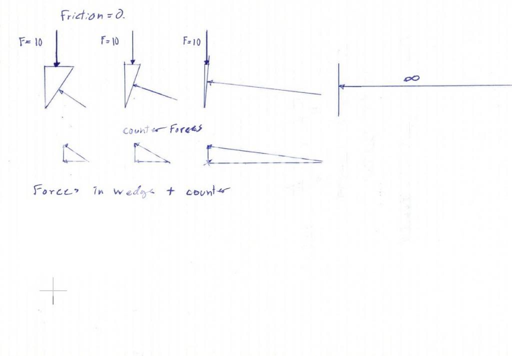
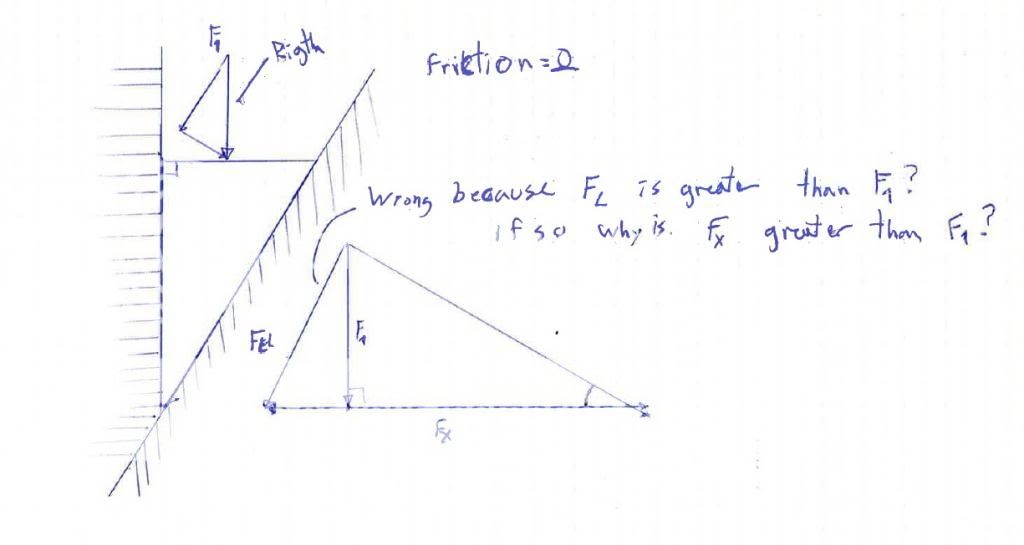
After much thought I think there is a fairly simple "real-life" way of explaining why the apparently same-shaped wedge generates different horizontal forces (that is; in the Fx direction at a right angle to the applied force F).
If you attack this problem from a "mechanical advantage" type of view: - in the first case (symmetrical wedge) if you calculate (by trigonometry) how far two points (I like to picture them as being like V8 roller bearing followers) are forced apart in a horizontal direction by 10 (for example) units of movement of the applied force F - and then use this distance to calculate the mechanical advantage - you get an MA of 2.836 - this gives a horizontal wedging force (Fx) of 28.36N if the applied force F is 10N.
In the second (non-symmetrical) case you find that per unit of movement of the applied force F the "followers" are being forced apart in a horizontal direction at a slightly higher rate - thus the distance they have moved after 10 units of movement of the applied force F is slightly more and the MA works out to be slightly less at 2.747 - resulting in a wedging force of 27.47N.
In the second case (non-symmetrical wedge) you find the the horizontal line of action of the "followers" lies across the wedge in a slightly "diagonal" manner an is thus a slightly longer distance compared to a horizontal line across the first (symmetrical) wedge.
Thus the more the wedge leans towards the left the longer the "diagonal" is, the lower the MA and the lower the wedging force is.
Also in the first example Mats calculated - I can't see that there is any Fxtotal of 56.71N that could be measured anywhere in the system - the force is 28.36N in both directions. Even if one "follower" is fixed and the other allowed to move - it is still 28.36 in both directions. Even with the non-symmetrical wedge it is still 27.47N in opposite directions.
Edited by Kelpiecross, 18 February 2013 - 04:46.