Jump to content


Photo
* * * * * 1 votes

A technical question about the DFV


  • Please log in to reply
90 replies to this topic

#1 gablet

gablet
  • Member

  • 124 posts
  • Joined: September 05

Posted 16 February 2013 - 21:23

Hi all,
I'm making researches about the first version of the FORD Cosworth DFV and I noticed an electric device that disappeared from 1968 onwards, here it is pointed with the red arrow:
Posted Image
With the blue arrows I pointed the 2 wires (in a single black insulation) exiting from the device and going towards the LUCAS OPUS system (judging by other 1967 Lotus 49 pictures) via a thin metal tube running over the righthand cam cover.
Does anybody know what was the purpose of this little box?
Many thanks in advance!
Best,
Gab

Advertisement

#2 Powersteer

Powersteer
  • Member

  • 2,460 posts
  • Joined: September 00

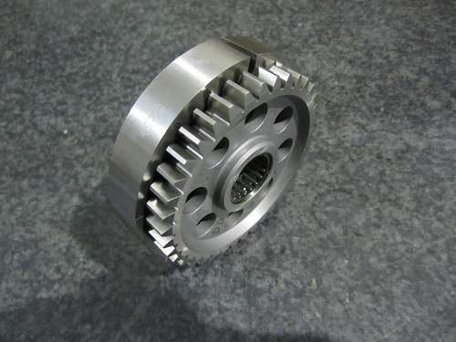
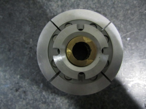
Posted 16 February 2013 - 23:51

Do you think it goes around the all the way from the left banks of intake to the top right camshaft?

:cool:

#3 bigleagueslider

bigleagueslider
  • Member

  • 1,235 posts
  • Joined: March 11

Posted 17 February 2013 - 03:26

Does anybody know what was the purpose of this little box?


Likely some sort of crank sensor for ignition timing. A 4-stroke engine controller needs two timing inputs, one for determining crank angle and one for determining which phase of the cycle it's on (ie. compression stroke vs exhaust stroke).


#4 gablet

gablet
  • Member

  • 124 posts
  • Joined: September 05

Posted 17 February 2013 - 08:12

Powersteer,
the thin metal tube is on the LEFT of the picture but I use to call "right" that side of the DFV because it WAS the right side of the engine.

Thanks bigleagueslider, that makes sense to me. :up:

Edited by gablet, 17 February 2013 - 11:51.


#5 Powersteer

Powersteer
  • Member

  • 2,460 posts
  • Joined: September 00

Posted 24 February 2013 - 14:24

Powersteer,
the thin metal tube is on the LEFT of the picture but I use to call "right" that side of the DFV because it WAS the right side of the engine.

Well the point I was trying to make was....do you think it run around the intake from one side to the other, crank to camshaft? Maybe its a sensor from the crank to cam to see how much cam the belt driven cam was giving away from belt flexing.

:cool:

#6 Tony Matthews

Tony Matthews
  • Member

  • 17,519 posts
  • Joined: September 08

Posted 24 February 2013 - 14:49

:D

...to see how much cam the belt driven cam was giving away from belt flexing.

The camshafts are gear-driven.

#7 gruntguru

gruntguru
  • Member

  • 7,635 posts
  • Joined: January 09

Posted 24 February 2013 - 23:19

So they are measuring how much the gears are flexing?

#8 Catalina Park

Catalina Park
  • Member

  • 6,766 posts
  • Joined: July 01

Posted 25 February 2013 - 07:35

If only we had a resident gear expert on the forum to help us out at times like these.

#9 Kelpiecross

Kelpiecross
  • Member

  • 1,730 posts
  • Joined: October 10

Posted 25 February 2013 - 07:52

So they are measuring how much the gears are flexing?


Would camshaft drive gears flex any appreciable amount? - Enough to cause a problem?

#10 Magoo

Magoo
  • Member

  • 3,694 posts
  • Joined: October 10

Posted 25 February 2013 - 07:58

What Slider said. For timing, the Lucas Opus ignition system (essentially) requires crank angle and cam position inputs, which are obtained via variable reluctance sensors.


http://www.grandprix...sworthstory.pdf

#11 Doug Nye

Doug Nye
  • Member

  • 11,512 posts
  • Joined: February 02

Posted 25 February 2013 - 08:28

...which are obtained via variable reluctance sensors.


http://www.grandprix...sworthstory.pdf


:confused:

DCN

#12 Magoo

Magoo
  • Member

  • 3,694 posts
  • Joined: October 10

Posted 25 February 2013 - 12:15

:confused:

DCN


OPUS is mentioned therein.

#13 gruntguru

gruntguru
  • Member

  • 7,635 posts
  • Joined: January 09

Posted 25 February 2013 - 23:18

Would camshaft drive gears flex any appreciable amount? - Enough to cause a problem?

No. :)

#14 Magoo

Magoo
  • Member

  • 3,694 posts
  • Joined: October 10

Posted 25 February 2013 - 23:31

What Slider said. For timing, the Lucas Opus ignition system (essentially) requires crank angle and cam position inputs, which are obtained via variable reluctance sensors.


http://www.grandprix...sworthstory.pdf


By the way: in the paper linked above, there is a discussion of the DFV's oft-mentioned TV issues, which might be said to sort of related to various cam drive issues as speculated here. Kind of.

#15 Lee Nicolle

Lee Nicolle
  • Member

  • 11,036 posts
  • Joined: July 08

Posted 26 February 2013 - 03:02

:rotfl:

If only we had a resident gear expert on the forum to help us out at times like these.


#16 Greg Locock

Greg Locock
  • Member

  • 6,349 posts
  • Joined: March 03

Posted 26 February 2013 - 03:44

No. :)

Never having worked on the king of cam drives I'll take your word for it, but certainly torsional deflection of the camshaft itself has given various people grief over the years. And just thinking about it, what about Delrin (???the brown resin impregnated cloth) gears and the like?

#17 gruntguru

gruntguru
  • Member

  • 7,635 posts
  • Joined: January 09

Posted 26 February 2013 - 05:32

My original post questioning whether Cosworth were using the sensor in question to measure flex in timing gears, was entirely tongue in cheek.

#18 Tony Matthews

Tony Matthews
  • Member

  • 17,519 posts
  • Joined: September 08

Posted 26 February 2013 - 08:25

I thought all the responses to that were tongue-in-cheek too...

#19 gruntguru

gruntguru
  • Member

  • 7,635 posts
  • Joined: January 09

Posted 26 February 2013 - 12:01

Oh good. Too subtle for me I'm afraid. :)

Advertisement

#20 Patrick Morgan

Patrick Morgan
  • Member

  • 253 posts
  • Joined: June 09

Posted 26 February 2013 - 12:43

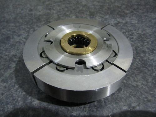
The DFV ran a flexible drive in its' compound gear - it's often referred to as the "Keith Duckworth Compliant Gear". I don't have one to hand but essentially the two gears are coupled together via a series of pins that allow for a small amount of deflection in an effort to decouple the torsional vibration of the bottom end from the stab torques of the valves. The down side of this is that your cam timing is compromised as you have to back it off enough to take the flex into account. The whole system must be very carefully looked after and regularly crack tested.

Although the Ilmor 265A is erroneously refereed to as being similar to the DFX (the Indy version of the DFV) one of the major differences was the absence of the compliant drive. This was probably the biggest issue with the engine and nearly killed the whole program. In the end Mario Illen came up with two pendulum mass dampers on the geartrain that solved the problem without compromising the cam timing.

All clever stuff.

Edited by Patrick Morgan, 26 February 2013 - 12:44.


#21 Kelpiecross

Kelpiecross
  • Member

  • 1,730 posts
  • Joined: October 10

Posted 26 February 2013 - 12:55

[quote name='Patrick Morgan' date='Feb 26 2013, 23:43' post='6142786']
The DFV ran a flexible drive in its' compound gear - it's often referred to as the "Keith Duckworth Compliant Gear". I don't have one to hand but essentially the two gears are coupled together via a series of pins that allow for a small amount of deflection in an effort to decouple the torsional vibration of the bottom end from the stab torques of the valves. The down side of this is that your cam timing is compromised as you have to back it off enough to take the flex into account. The whole system must be very carefully looked after and regularly crack tested.

Now I am not sure if this is not just another obscure joke - your fault GG.


#22 Magoo

Magoo
  • Member

  • 3,694 posts
  • Joined: October 10

Posted 26 February 2013 - 14:12

Posted Image


LINK --------> http://www.grandprixengines.co.uk/cosworthstory.pdf <----------LINK


.

#23 Tony Matthews

Tony Matthews
  • Member

  • 17,519 posts
  • Joined: September 08

Posted 26 February 2013 - 15:51

Now I am not sure if this is not just another obscure joke - your fault GG.

It's all in the PDF, and here is a photo...

Posted Image


#24 Tony Matthews

Tony Matthews
  • Member

  • 17,519 posts
  • Joined: September 08

Posted 26 February 2013 - 15:53

I have a photograph of the Ilmor damper, but I was sworn to secrecy and not allowed to show it in any cutaways. I assume one big advantage was/is that it doesn't affect backlash.

#25 Nigel Beresford

Nigel Beresford
  • Member

  • 1,087 posts
  • Joined: February 09

Posted 26 February 2013 - 16:41

Now I am not sure if this is not just another obscure joke - your fault GG.


I'd guess you don't know who Patrick is, otherwise you'd know it isn't a joke.

Edited by Nigel Beresford, 26 February 2013 - 16:46.


#26 Patrick Morgan

Patrick Morgan
  • Member

  • 253 posts
  • Joined: June 09

Posted 26 February 2013 - 17:22

I have a photograph of the Ilmor damper, but I was sworn to secrecy and not allowed to show it in any cutaways. I assume one big advantage was/is that it doesn't affect backlash.


Well I guess enough time has gone by and there are plenty of 265A's in private hands....

Posted Image
Ilmor 265A damper by dtperformanceltd, on Flickr

Posted Image
Ilmor 265A damper rear view by dtperformanceltd, on Flickr

Posted Image
Ilmor 265A damper side view by dtperformanceltd, on Flickr

#27 Patrick Morgan

Patrick Morgan
  • Member

  • 253 posts
  • Joined: June 09

Posted 26 February 2013 - 17:45

It's all in the PDF, and here is a photo...

Posted Image


Tony, there is no end to your treasure trove. Thanks, that's the item. It's a very cleaver solution. That's what's so neat about restoring older stuff, you get to see lots of different solutions to the same problem.


#28 Powersteer

Powersteer
  • Member

  • 2,460 posts
  • Joined: September 00

Posted 26 February 2013 - 19:54

:D
The camshafts are gear-driven.

Didn't know that one...flexing gears is funny though.

:cool:

#29 Patrick Morgan

Patrick Morgan
  • Member

  • 253 posts
  • Joined: June 09

Posted 27 February 2013 - 08:30

I asked one of my guys about the sensor this morning. He built DFV's in the late 1970's / early 1980's. It seems to be the crank trigger but of a much earlier style than what he was used to. Neather of us could work out what it triggered off?? Possibly the trigger disc is missing in the photo. It is certainly a very early photograph - the fuel pump is mounted on the engine (although curiously the bevel drive for the cable seems to be present as well) and the ignition unit looks to have a fabricated cover. The trumpets are certainly very early.

Hope that helps.

Edited by Patrick Morgan, 27 February 2013 - 08:33.


#30 Magoo

Magoo
  • Member

  • 3,694 posts
  • Joined: October 10

Posted 27 February 2013 - 09:56

I asked one of my guys about the sensor this morning. He built DFV's in the late 1970's / early 1980's. It seems to be the crank trigger but of a much earlier style than what he was used to. Neather of us could work out what it triggered off?? Possibly the trigger disc is missing in the photo. It is certainly a very early photograph - the fuel pump is mounted on the engine (although curiously the bevel drive for the cable seems to be present as well) and the ignition unit looks to have a fabricated cover. The trumpets are certainly very early.

Hope that helps.


In numerous sources, reference is made to a "40-tooth reluctor wheel attached to the front of the crankshaft," which obviously is not installed in this photo.

#31 Kelpiecross

Kelpiecross
  • Member

  • 1,730 posts
  • Joined: October 10

Posted 27 February 2013 - 12:21


I have to say in defence of my apparent stupidity that I have never heard of another similar racing engine to the DFV that had a similar "compliant" gear. If the DFV is the only one - why did it need such a thing?

Oddly enough I think I have seen a vaguely similar arrangement on a road-going Toyota (I think it was a Toyota) twin-cam engine. In this engine the second camshaft was driven from the first camshaft by a split, spring-loaded gear - presumably to overcome rattling/chattering noises from the "stab torques".


#32 Patrick Morgan

Patrick Morgan
  • Member

  • 253 posts
  • Joined: June 09

Posted 27 February 2013 - 12:42

I have to say in defence of my apparent stupidity that I have never heard of another similar racing engine to the DFV that had a similar "compliant" gear. If the DFV is the only one - why did it need such a thing?

Oddly enough I think I have seen a vaguely similar arrangement on a road-going Toyota (I think it was a Toyota) twin-cam engine. In this engine the second camshaft was driven from the first camshaft by a split, spring-loaded gear - presumably to overcome rattling/chattering noises from the "stab torques".


You are not being stupid at all - the DFV was, as far as I know, the first engine to have such a thing hence it was called the "Keith Duckworth compliant gear". Balance and torsional vibration is an extremely complex subject, one I cannot hope to ever understand properly. Different people do different things. Some of the F1 V8 engine for example seem to couple the two cams together both at the front and the back to more the "nodes" and reduce cam twist. If you look at photos of the BMW engine from 2008 for example that had lumps both front and back of the cam cover. Some aero engines (the Write Cyclone is the first that comes to mind) had a mass damper that floated on the crank web. I dread to think how heavy that is!

The Judd EV engine from 1990 has the same compliant gear arrangement as the DFV on the pump drives albeit much smaller. In an ideal world you would try to get away for anything twisting if you can and the mass damper is not a bad way to do it but it does add inertia to the system.

#33 Magoo

Magoo
  • Member

  • 3,694 posts
  • Joined: October 10

Posted 27 February 2013 - 13:15

Oddly enough I think I have seen a vaguely similar arrangement on a road-going Toyota (I think it was a Toyota) twin-cam engine. In this engine the second camshaft was driven from the first camshaft by a split, spring-loaded gear - presumably to overcome rattling/chattering noises from the "stab torques".


Very common on production DOHC V6/V8, particularly Japanese. Chain pretensioner, sort of.


#34 Magoo

Magoo
  • Member

  • 3,694 posts
  • Joined: October 10

Posted 27 February 2013 - 13:19

You are not being stupid at all - the DFV was, as far as I know, the first engine to have such a thing hence it was called the "Keith Duckworth compliant gear". Balance and torsional vibration is an extremely complex subject, one I cannot hope to ever understand properly. Different people do different things. Some of the F1 V8 engine for example seem to couple the two cams together both at the front and the back to more the "nodes" and reduce cam twist. If you look at photos of the BMW engine from 2008 for example that had lumps both front and back of the cam cover. Some aero engines (the Write Cyclone is the first that comes to mind) had a mass damper that floated on the crank web. I dread to think how heavy that is!

The Judd EV engine from 1990 has the same compliant gear arrangement as the DFV on the pump drives albeit much smaller. In an ideal world you would try to get away for anything twisting if you can and the mass damper is not a bad way to do it but it does add inertia to the system.


The big aircraft radials used a depleted uranium mass. There was quite an assortment of cam dampers on the IRL V8s. As you said earlier, "That's what's so neat about restoring older stuff, you get to see lots of different solutions to the same problem." That's it exactly. The most fascinating stuff in the world.


#35 Tony Matthews

Tony Matthews
  • Member

  • 17,519 posts
  • Joined: September 08

Posted 27 February 2013 - 18:10

In numerous sources, reference is made to a "40-tooth reluctor wheel attached to the front of the crankshaft," which obviously is not installed in this photo.

Posted Image
A detail from Theo Page's cutaway of the early DFV showing the 40-tooth cross-cut blade.

Posted Image
A later trigger/sensor set-up on a later DFV, or perhaps a DFY.

Posted Image
The same unit on a DFX...

Posted Image
...in close-up.


Edited by Tony Matthews, 27 February 2013 - 18:27.


#36 Tony Matthews

Tony Matthews
  • Member

  • 17,519 posts
  • Joined: September 08

Posted 27 February 2013 - 18:33

And while I'm at it, a detail from my cutaway of the DFX showing the "Keith Duckworth Compliant Gear" and a bare crankshaft nose. Either a different system was in use, or I missed it and no-one complained at the time.

Posted Image

Edited by Tony Matthews, 27 February 2013 - 20:40.


#37 rachael

rachael
  • Member

  • 118 posts
  • Joined: October 10

Posted 27 February 2013 - 20:48

Oddly enough I think I have seen a vaguely similar arrangement on a road-going Toyota (I think it was a Toyota) twin-cam engine. In this engine the second camshaft was driven from the first camshaft by a split, spring-loaded gear - presumably to overcome rattling/chattering noises from the "stab torques".


It's called a scissor gear - used for NVH reasons not timing.

#38 gruntguru

gruntguru
  • Member

  • 7,635 posts
  • Joined: January 09

Posted 27 February 2013 - 23:09

Oddly enough I think I have seen a vaguely similar arrangement on a road-going Toyota (I think it was a Toyota) twin-cam engine. In this engine the second camshaft was driven from the first camshaft by a split, spring-loaded gear - presumably to overcome rattling/chattering noises from the "stab torques".

Eliminates backlash by maintaing pressure on both leading and trailing faces of the gears. Problems arising from backlash include NVH and resonances and accelerated wear.

#39 gruntguru

gruntguru
  • Member

  • 7,635 posts
  • Joined: January 09

Posted 27 February 2013 - 23:16

Some aero engines (the Write Cyclone is the first that comes to mind) had a mass damper that floated on the crank web. I dread to think how heavy that is!

Fairly common - a device to damp crankshaft torsional vibrations. The DFV device is much less common in damping the drive between two seperate shafts. Napier had to put something like that between the two (geared) crankshafts of the H-24 Sabre.

Advertisement

#40 Charles E Taylor

Charles E Taylor
  • Member

  • 213 posts
  • Joined: December 07

Posted 27 February 2013 - 23:25

Cosworth Crank Torsional Damper.


The DFV was not the first Cosworth engine to use a Crank/Camdrive damper.

If you look at the 1000cc Cosworth SCA closely you will find an earlier implementation of a Torsional Crank Damper by Costin & Duckworth


Photos and cutaway drawings are available on the interweb elsewhere.


I hope that adds some additional flavor.


Charlie

#41 GreenMachine

GreenMachine
  • Member

  • 2,629 posts
  • Joined: March 04

Posted 28 February 2013 - 02:59

I believe superchargers (some anyway) decouple the rotors from the drive pulley to isolate the rotors from some of the forces acting on the pulley.

#42 Charles E Taylor

Charles E Taylor
  • Member

  • 213 posts
  • Joined: December 07

Posted 28 February 2013 - 10:50

Torsional Dampers in F1 engines


It is interesting to see the extent of Torsional Vibration Damping in current F1 Engines. I understand the Cosworth CA has 7 TVD systems. The large base diameter hollow camshafts are driven by an internal quill shaft. No doubt sized to manage the excitation frequency's involved.

There is a lot of ringing going on at 18K RPM.


It is a pity that all these companies are so secretive now.


The more you look the more you see!


Charlie

#43 carlt

carlt
  • Member

  • 4,169 posts
  • Joined: June 09

Posted 28 February 2013 - 11:22

I was under the [misguided?] impression that they all used some form of pneumatic or solenoid driven valves

#44 MatsNorway

MatsNorway
  • Member

  • 2,822 posts
  • Joined: December 09

Posted 28 February 2013 - 11:52

Would not belts dampen the smaller vibrations?

Basically any serious drag racing thingy ive seen got belts. Belts belts belts. all over the place.

Posted Image

Edited by MatsNorway, 28 February 2013 - 11:58.


#45 Tony Matthews

Tony Matthews
  • Member

  • 17,519 posts
  • Joined: September 08

Posted 28 February 2013 - 11:55

I was under the [misguided?] impression that they all used some form of pneumatic or solenoid driven valves

Pneumatically closed, but opened via camshafts. How long that will remain we shall see. Charles is right, there was a time when new technology was trumpeted, now you can't find out much more than rumour and conjecture. Conjecture - today's special word.

The Ferrari 049 engine had TVBs on the camshafts, at the rear of the engine, with the geartrain at the front. I wasn't allowed to see them.

#46 Wuzak

Wuzak
  • Member

  • 8,400 posts
  • Joined: September 00

Posted 28 February 2013 - 12:45

The big aircraft radials used a depleted uranium mass. There was quite an assortment of cam dampers on the IRL V8s. As you said earlier, "That's what's so neat about restoring older stuff, you get to see lots of different solutions to the same problem." That's it exactly. The most fascinating stuff in the world.


Depleted Uranium? In the '30s and '40s?

Pratt & Whitney's R-2800 went through a lot of development with regards to TVs. The A and B series engines had tungsten weights bolted to the crank counterweights, with a pair of floating "hockey puck" dampers on one. They were also tungsten.

Later R-2800s used basically floating counterweights on front and rear counterweights. One was tuned to damp 2nd order vibrations, the other 4.5 order vibration.

#47 Wuzak

Wuzak
  • Member

  • 8,400 posts
  • Joined: September 00

Posted 28 February 2013 - 13:26

Fairly common - a device to damp crankshaft torsional vibrations. The DFV device is much less common in damping the drive between two seperate shafts. Napier had to put something like that between the two (geared) crankshafts of the H-24 Sabre.


Aero engines often used torsionally flexible shafts to connect things together. Not sure if there were any between the Sabre's cranks and the reduction gear.

Each crankshaft drove two gears through straight cut spur gears. Those were attached to helically cut gears which drove the main reduction gear. These gears were mounted on a sprung balance beam. I can't quite see how the sleeve drive shafts are driven, but it looks to be from one of the first stage reduction gears on each side.

The supercharger was driven by torsionally flexible shafts which ran from the reduction gear through the sleeve drive shaft to the supercharger gears.


The Allison V-1710 had a TV damper at the rear of the crankshaft. The Rolls-Royce Merlin did not - it relied on torsionally flexible shafts. The clutches in the supercharger drive also had some slip allowed.

Both the Allison and Merlin had the cam drives off the rear of the engine. The Griffon had all accesories driven off the front (with the reduction gear) as well as the came drive. Originally the supercharger drive was taken from the front, but later versions had that coming off the rear. I think drive was taken from the front to remove as much variation between crank and cams as they could.

#48 Magoo

Magoo
  • Member

  • 3,694 posts
  • Joined: October 10

Posted 28 February 2013 - 13:42

Depleted Uranium? In the '30s and '40s?


In the '50s.


#49 gablet

gablet
  • Member

  • 124 posts
  • Joined: September 05

Posted 28 February 2013 - 19:26

Thanks to you all for making this thread so interesting :up:
A special thanks to Tony Matthews for his pictures that, as always, are truly priceless gems!
Gab

#50 carlt

carlt
  • Member

  • 4,169 posts
  • Joined: June 09

Posted 28 February 2013 - 21:18

purely by coincidence this came up on another forum

Koenigsegg free valve actuators -

http://www.youtube.c...p;v=Bch5B23_pu0

- surprised no F1 engine uses such tech. - the capability to essentially have a square-ish cam profile and infinitely variable - incredible potential