One-sided Ferrari
#1

Posted 23 June 2013 - 08:49
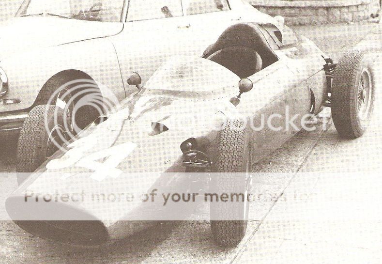
I have just completed a 32nd scale slot car of the first rear-engined Ferrari F.1 car. This is the car that appeared just once in 2.5 litre form, at Monaco in 1960 driven by Richie Ginther. It has long puzzled me why the car had a clear plastic air scoop on one side of the engine cover, through which could be seen three intake trumpets. For many years I have wondered why there wasn't something similar on the other side of the car, feeding the other half of the V.6 engine.
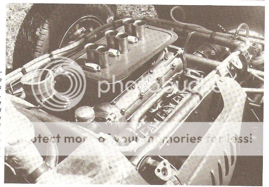
Then, just the other day I was looking at the front-engined car from the same year and it dawned on me that the two sets of trumpets were very close together and given that I assume the engine in Ginther's car was the same as in the regular cars the one scoop would feed all 6 intakes.
But this raises another question. The intakes are very much on the left side of the car so I'm now wondering if the engine was canted over, thus moving the intakes off the centre line of the car and much more to one side.
It's taken a long time to make this car - pity it's only going to race once......
#3

Posted 23 June 2013 - 10:19
Here's a related thread.
http://forums.autosp...showtopic=12802
#4

Posted 27 June 2013 - 09:25

From A-Z Of Formula Cars book.......Here is the other side of the story Barry.
Uploaded with ImageShack.us
#5

Posted 27 June 2013 - 09:49
Looking at the pictures of this car and the models I have (not the one made by me I hasten to add) I still can't accept that the engine is mounted on the centre line of the car. Those intakes are far too close to the left side of the engine cover so unless they had some unusual shaped intakes I just don't see how this engine can be centrally mounted.
I'm not for one second suggesting it was tilted - I know it wasn't, but I'd love to see what it all looked like under that engine cover.
And... while I'm on about it, if you draw an imaginary line from the top of those intakes, forward to the front of the car, you will see that they are way higher than they were when the engine was front-mounted. Why?
#6

Posted 27 June 2013 - 10:23
I'm fairly well known for 'banging on' about stuff but I'm afraid I've got to bang on again.
Looking at the pictures of this car and the models I have (not the one made by me I hasten to add) I still can't accept that the engine is mounted on the centre line of the car. Those intakes are far too close to the left side of the engine cover so unless they had some unusual shaped intakes I just don't see how this engine can be centrally mounted.
I'm not for one second suggesting it was tilted - I know it wasn't, but I'd love to see what it all looked like under that engine cover.
And... while I'm on about it, if you draw an imaginary line from the top of those intakes, forward to the front of the car, you will see that they are way higher than they were when the engine was front-mounted. Why?
I think the bonnet line is much lower in the rear engined car.
#7

Posted 27 June 2013 - 15:44
I think the scoop feeds an airbox with the LH bank of trumpets visible (obviously) and the RH bank beyond, lurking in the gloom.
I have just found a photograph of the car minus the scoop, just a small rectangular hole.
Edited by Tony Matthews, 27 June 2013 - 15:51.
#8

Posted 27 June 2013 - 16:36
#9

Posted 27 June 2013 - 17:54

While there are a lot of photos of the prototype car, I have never seen one with the engine cover open.
However, it was modified later in the season, and here is a picture showing that they kept the same seat:

Looking at the proportions of the engine in relation to the seat, it must just be the way the light catches the left-hand inlet trumpets in the colour views, and it must be central within the large but narrow humped engine cover.
Paul M
#10

Posted 27 June 2013 - 18:12
#11

Posted 27 June 2013 - 19:54
My guess is, that inside the engine cover they may have been a box, or chamber, that when the cover was on, created a sort of internal airbox , though it still would ask the question, why not put one scoop on each side?
Could it be the scoop was a front engine item and one was enough on that, or the parts department at Maranello had run out of stock ?
#12

Posted 27 June 2013 - 21:24
Dale.
#13

Posted 28 June 2013 - 06:19
#15

Posted 28 June 2013 - 12:47
#17

Posted 28 June 2013 - 14:48
Pretty much sure engine was symmetrical in the rear. All Dino 156's had it later as well. Hope you can sleep better now Barry!
#18

Posted 28 June 2013 - 15:47
I just can't get past the feeling that the three visible intakes are much closer to the left side of the car than the right. Everyone has proved they aren't.
It's just an optical delusion.
#19

Posted 28 June 2013 - 16:10
Mind you, its a Ferrari! ;-)It's just an optical delusion.
Advertisement
#20

Posted 28 June 2013 - 17:04
Originally posed by Barry Boor
.....And... while I'm on about it, if you draw an imaginary line from the top of those intakes, forward to the front of the car, you will see that they are way higher than they were when the engine was front-mounted. Why?
I think you're right here, but not totally sure...
I will offer a suggestion, though. When the engine was in the front there was a lot of room to run a driveshaft 'uphill' to get to the level required for the final drive.
With the engine bolted directly to the final drive, however, only the halfshafts gave that latitude and they might not have been able to absorb the same difference in height.
For what it's worth...
I note that the offset plate shown in the photo above (which has been scanned, have I ever mentioned that if you photograph with a digital camera you don't get that pattern in the pic?) is not drawn as such in the cutaway.


