Jump to content


Photo
- - - - -

A-arm end solutions


  • Please log in to reply
23 replies to this topic

#1 NeilR

NeilR
  • Member

  • 623 posts
  • Joined: October 09

Posted 23 July 2013 - 04:43

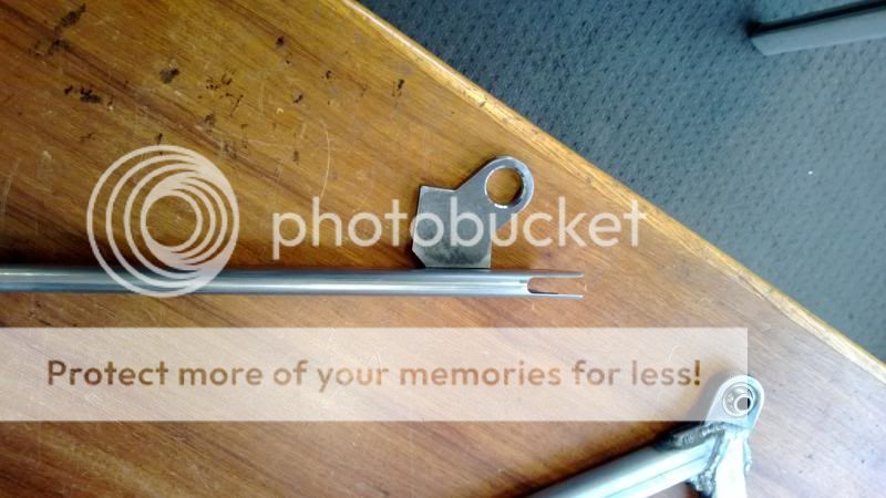
I've got to the point on a couple of projects to making A-arms. Talking to a friend we decided to try different methods to locating the bearings (I know we are not inventing anything new, we are not that clever) and decided on the following:

Posted Image

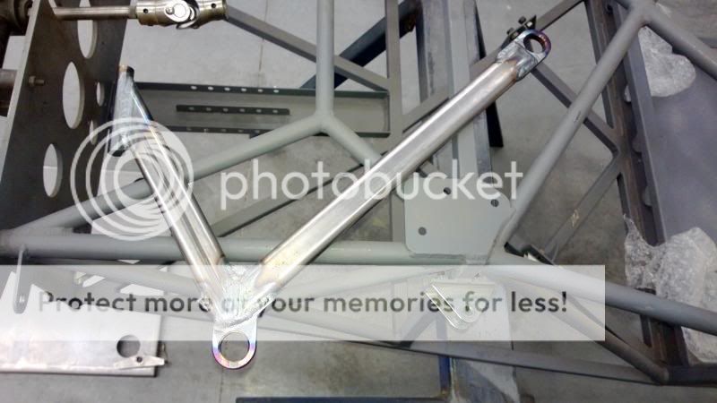
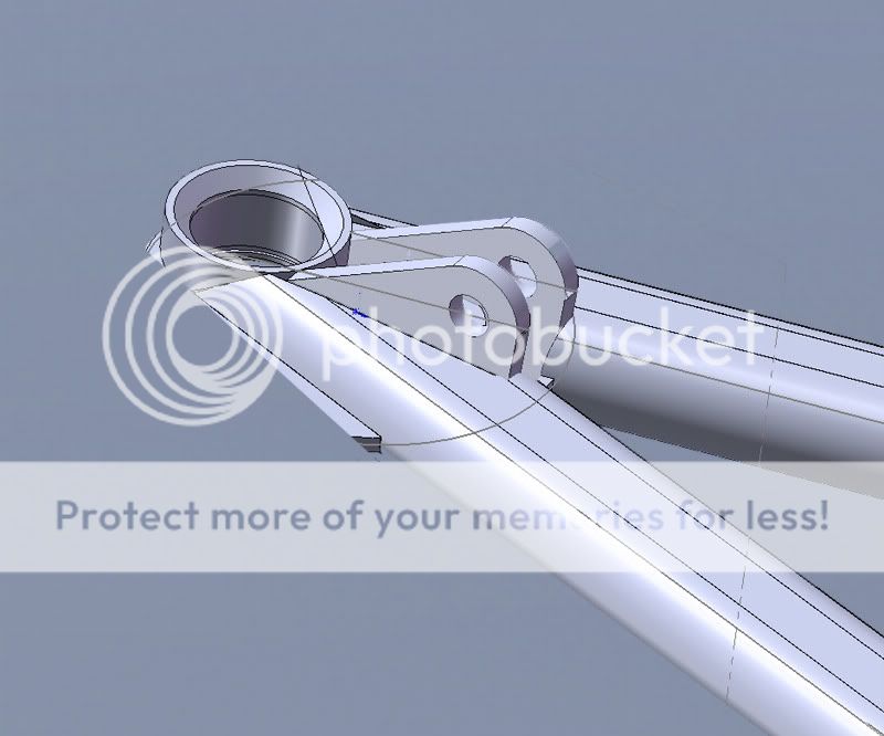
A laser cut outer plate (10mm thick) and milled slots in the tubes. The bearing is then pressed into the plate after welding and staked into place, as you can see. Once we know they work, lighter versions will be made.

Posted Image

The full wishbone on this car looks like this. I am wondering if there would be any benefit in having one side of the plate that slots into the tube longer so that the welds do not terminate at the same point along the tube?
Secondly I would like to use this method on a road car (with round tube), but with a Ford ball joint pressed (interference fit) into the plate, retained with a circlip on the bottom as per the OEM arm. Does this sound reasonable?

Edited by NeilR, 23 July 2013 - 04:44.


Advertisement

#2 rory57

rory57
  • Member

  • 98 posts
  • Joined: November 10

Posted 23 July 2013 - 08:45

I would like to use this method on a road car (with round tube), but with a Ford ball joint pressed (interference fit) into the plate, retained with a circlip on the bottom as per the OEM arm.


I would be worried that the part cut from plate would be too soft to support the interference fit of the pressed-in ball joint. These ball joints are normally fitted to forged arms are they not?

#3 Grumbles

Grumbles
  • Member

  • 326 posts
  • Joined: September 09

Posted 23 July 2013 - 09:16

I would be worried that the part cut from plate would be too soft to support the interference fit of the pressed-in ball joint. These ball joints are normally fitted to forged arms are they not?


Eleventy billion GM vehicles had ball joints pressed into control arms stamped from thin steel plate. The holes weren't machined, just punched out, and the balljoint OD was usually knurled. I think your brackets will be fine. If they loosen over time you'd just leave a bit more meat around the bore.

Something to keep in mind with these projects (and I realize I'm stating the obvious) is that these things don't always have to be the absolutely perfect solution, they just have to be good enough. If you try to make every little detail technically perfect you just getted bogged down to the point where nothing gets finished. And even if it did it wouldn't have worked any better than something made Good Enough anyway.

#4 NeilR

NeilR
  • Member

  • 623 posts
  • Joined: October 09

Posted 23 July 2013 - 09:53

Rory, Grumbles is correct about the suspension arms. The mitsubishi ones I have are stamped from thin steel and welded together to form a large box section. The ball joint is pressed into a stamped hole which has a 10mm lip. Half of the BL hole is supported by a 20mm lip. The Ford suspension arms are currently forged alloy. I can of course use a better grade of steel for the plate and remove some of the metal to lighten it, or even water cut the steel, as long as it is still weldable...and locally available.
Grumbles, yes I have fallen into the tramp of perfecting things and it has wasted a lot of time...years in fact. Thanks for both replies.
Any other thoughts welcome.

Edited by NeilR, 23 July 2013 - 09:53.


#5 mariner

mariner
  • Member

  • 2,334 posts
  • Joined: January 07

Posted 23 July 2013 - 19:45

It may be an unavoidable detail ( steering lock?) but the way the plates are welded up leaving the BJ joint area of the plate sticking out will put very large twisting loads into the welds.
If you can get the centre axes of each strut pointing at the BJ hole centre the loads wil be more straight push/pull.

I think most of the OEM stampings which use pressed in BJ's have, in effect , a load path which avoids lots of torsional load near the BJ hole.

#6 kikiturbo2

kikiturbo2
  • Member

  • 869 posts
  • Joined: December 04

Posted 23 July 2013 - 19:55

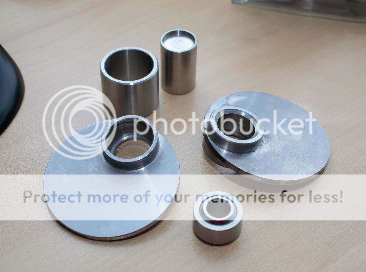
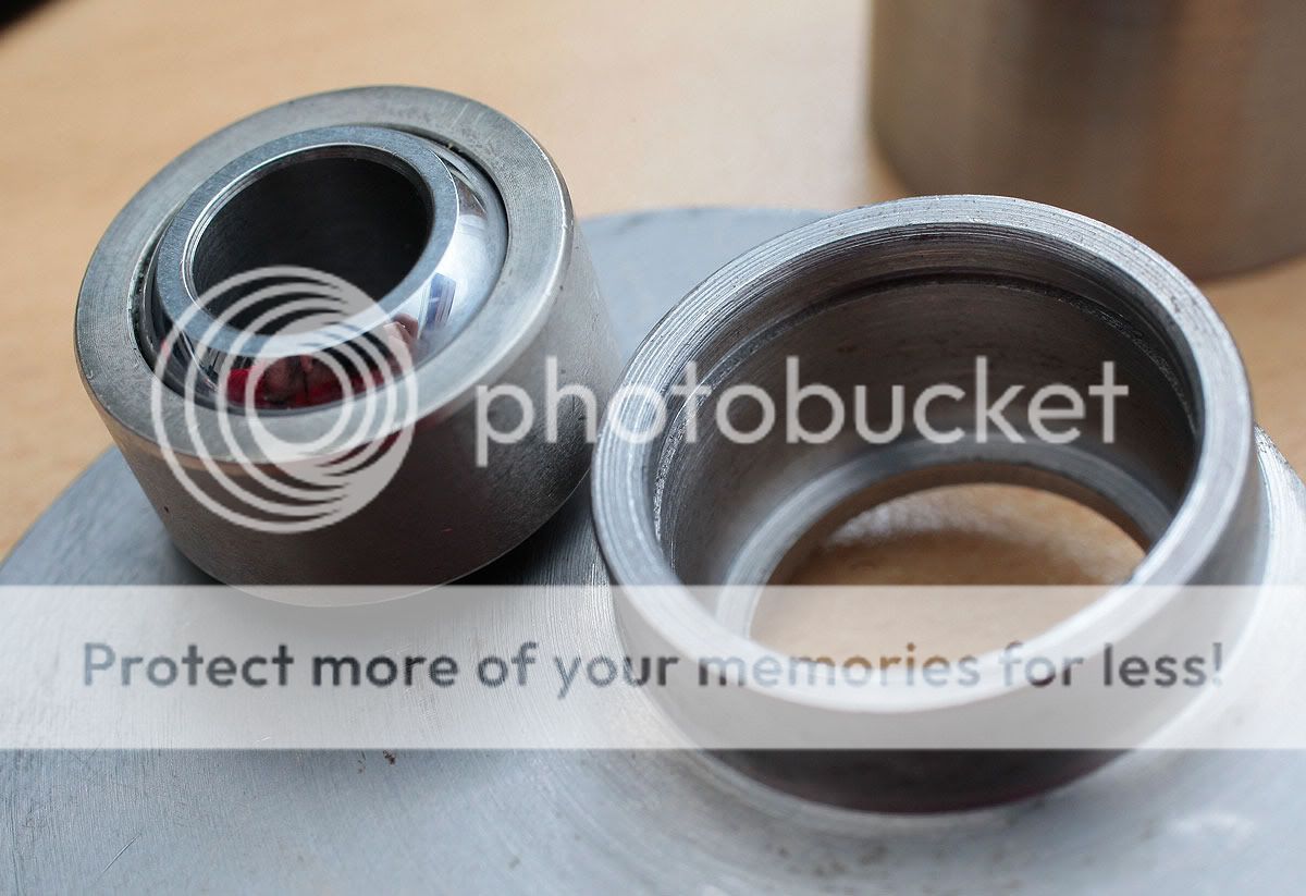
here is my solution... a bit complicated I guess because the housings need to be turned from solid bar...

Posted Image

Posted Image

Posted Image

pushrod attachment is welded on, and is positioned in such a way as for the projection of the pushrod to intersect with the centre of the spherical joint... not to have any bending in the a arms..

the excess will be cut after welding, and the size of the unit spreads loads over larger welding area... i.e. not to have just a small weld on the end of the tubes..

Edited by kikiturbo2, 23 July 2013 - 19:57.


#7 NeilR

NeilR
  • Member

  • 623 posts
  • Joined: October 09

Posted 23 July 2013 - 22:09

Mariner thanks for that, I'll have another look at them on the big car, though I seem to recall the Mitsubishi arm does not intersect the ball centre - I'll try to get a photo. The A arms above are for an ADR1000, which is around 350kg or so and powered by a BMW motorbike engine, so they are fairly stout for the job. But you are correct, they were made that way to get some reasonable steering lock for maneuvering around pits and garages. I have planned some offset on the road car (overshoot if you will, where the intersect is outside of the ball joint centreline) on the top A arms to get additional clearance for the spring and damper.

Kiki that is a very nice solution and I'm happy someone thought the same way - how thick are the plates?
We had considered machining up a tube that is then welded into the plate for the Ford ball joint, as that presses into a 19mm deep 'cup'.
As my car is likely to be a road car I had a preference to use a OEM ball joint - at least for the majority of it's life. The greatest reason for doing this is to keep the certifying engineer happy and easing the engineering process. He also would like me to use tube for the A -arms that is 35mm x 2.5mm DOM and a minimum of 350Mpa. The tube I have is not very formable and squashing it down to fit the bearing cup in a traditional way seemed problematic.


#8 mariner

mariner
  • Member

  • 2,334 posts
  • Joined: January 07

Posted 24 July 2013 - 15:18

couple more thoughts - and congratulations to Kikki for a neat solution.


Neil ,you either didn't mention camber adjustment or I missed it. In reality I think most suspension links have lots of nasty bending loads because if you use a threaded ball joint to do camber adjustment then the arm axes will not be at the BJ centre etc. The need for steering lock adds to this and if you use long radius arm it needs to be clear of the front wheel swing so it often picks up back along the lateral link ( Brabham etc.)

There is one other thing you COULD do but if you want to finish your car I dont suggest it!

You can use two seperate lower arms which attach to the hub in two places , giving a virtual pivot point. I think BMW did this once on road car. The advantages are

1) you can use two straight , light arms with a threaded BJ fiting so as to get pure tension/compression in the arms AND adjust camber.

2) You can get more lock ( or a wider wishbone base) because as the wheel rim approaches that arm that arm is being moved away from it by the geometry.

3) You can mitigate against the tendency of high camber angles adding negative camber at high lock angles because the virtual centre point can be made to migrate inwards as lock builds up

Now thats al very well but Greg etc can probably mention a dozen reasons why its more trouble than its worth. If he is efeling very kind he might tel me whether better kinematics control with soft bushings is of any possible benefit!

PS I did mis it, your camber adjustment is at the chasis end of the forward arm I think!

Edited by mariner, 24 July 2013 - 15:19.

#9 Greg Locock

Greg Locock
  • Member

  • 6,366 posts
  • Joined: March 03

Posted 24 July 2013 - 21:24

I think there is a significant difference between pushing a bearing into a drawn, filleted, hole, and into a hole drilled in a thick sheet. The former will provide more support along the length of the bearing, and because it is more compliant, it will be more robust.

That's not to say that interference fits won't work in a solid plate, but they will be more sensitive to dimensions and wear.

#10 JimboJones

JimboJones
  • Member

  • 97 posts
  • Joined: February 12

Posted 24 July 2013 - 22:11

NeilR,

I would suggest that the 'plates' used in both methods pictured above are completely unnecessary. Simply turn a housing from bar stock, just like kiki's but without the additional disc of metal around it, and weld the tubes directly to this, with their centrelines intersecting the hole centre (for pure tension/compression). The housing should be reamed post weld for the best tolerance though in case of any distortion during the weld, unless your using a particularly thick walled housing (in which case you may get away with finishing the ID on the lathe.
The plate offers little in the way of strength as it compromises the inherent stiffness of the tube, and you just add a load of weight, and welding! Go check out how neat some of the formula student solutions are - you'll be amazed how delicate a strong design can appear (albeit for a much lighter car, but you'll get some ideas nonetheless).

#11 gruntguru

gruntguru
  • Member

  • 7,642 posts
  • Joined: January 09

Posted 24 July 2013 - 22:20

:up:

#12 NeilR

NeilR
  • Member

  • 623 posts
  • Joined: October 09

Posted 24 July 2013 - 23:46

I'll take some photo's today that might help.
Mariner, the camber adjustment is done at the chassis mounts with shims.

Edit: back now.
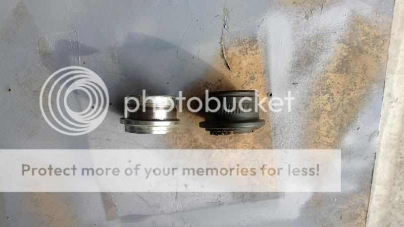
OEM ball joint housings look like this. The black is Ford and the silver is Mitsubishi (same brand as OEM uprights front and rear). The depth from the lip to the circlip on the miti one is 10mm and the ford 19mm. You can see that machining a cup like Kiki is not an option. If a cup were machined it would be 10mm for the miti one and joining a 32mm x 2.5mm tube to 10mm is the challenge.

Posted Image

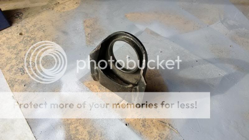
The end of the Miti arm looks like this. We had considered recycling them, but it would be difficult and I am sure that the geometry of the A arm would be poor.

Posted Image

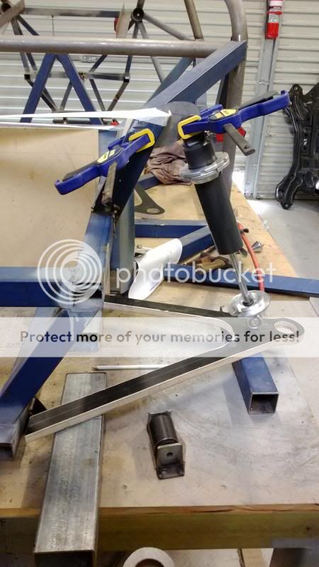
Mocking up the front damper mounts:

Posted Image

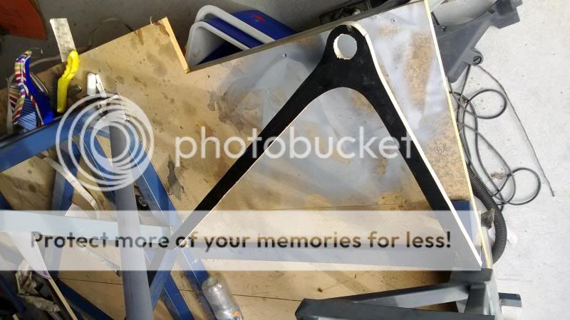
Lower arm mockup propped in place. The large gap between the front and rear bearing is necessary to clear the transmission of the transverse V6.

Posted Image

Edited by NeilR, 25 July 2013 - 00:45.


#13 Lee Nicolle

Lee Nicolle
  • Member

  • 11,069 posts
  • Joined: July 08

Posted 25 July 2013 - 00:28

While I have no idea of legalities. For a light weight car I feel the spherical bearing is ok.Personally I would probably use a lightly bigger one though I always overengineer things. Clearly it will not be an everyday driver. What a 1000km a year?
I was looking at 2 Clubbie style cars on Sunday, one used an equal length A arm with a ball joint and one used a quite unequal length arm with a bearing. Both are registered and street driven.
A early Holden ball joint is the way to go if you use ball joints. The lower presses in and the upper bolts in. If you wish to further space your uprights use a Commodore lower ball joint, it goes in the same hole and is about 40mm taller. This is the units used by K&A with Corvette uprights on all the Sports Sedans. And many Speedway Super sedans use them too, usually just with a Holden HQ stub. The HQ stub is a LOT stronger than all the others. The Holden steering arms bolt to the stub and all interchange from HD-WB and all Torana so you should be able to sort out steering geometry too. The Holden stubs also use a semi standard bolt pattern with many other US, English cars. I have a Torana with HQ stubs, 290mm Commodore rotors and Jag 4 spots,,, which all bolts together. Some Willwood and AP callipers also use that bolt spacing
It will ofcourse be fairly heavy for a little car but VERY strong.
The only thing wrong is when using short springs that do not hold constant pressure up is that the lower balljoints can fall out of the hole. Most tack them to the wishbone, problem solved. Those balljoints interchange with many US GM proper cars too.

Edited by Lee Nicolle, 25 July 2013 - 01:14.


#14 NeilR

NeilR
  • Member

  • 623 posts
  • Joined: October 09

Posted 25 July 2013 - 00:48

Actually Lee I hope to use the car a lot, so maybe up to 10,000km per year? Hopeful I know.
Greg we could form sheet in a press to match the MMAL arm. What are the Ford arm's like?

Edited by NeilR, 25 July 2013 - 01:04.


#15 Greg Locock

Greg Locock
  • Member

  • 6,366 posts
  • Joined: March 03

Posted 25 July 2013 - 04:33

Actually Lee I hope to use the car a lot, so maybe up to 10,000km per year? Hopeful I know.
Greg we could form sheet in a press to match the MMAL arm. What are the Ford arm's like?


Which bush from which car is that, is it that shock absorber one? the knurling is there to reduce the sensitivity of the bush to dimensional variation, or else a desperate attempt to improve retention (I think the former). If the bush does seem a bit loose 700 series Loctite solves all manner of evils, providing the bush housing is long enough.


#16 NeilR

NeilR
  • Member

  • 623 posts
  • Joined: October 09

Posted 25 July 2013 - 04:47

yes, suspension bush is the damper one actually in it's housing and mount in the front of the third picture above. It would be easy to use a spherical bearing mounted at the bulkhead for the lower rear A-arm pictured.
The knurled ball joint housing (actual ball joint was removed to measure it) is BA and prior Falcon.

#17 kikiturbo2

kikiturbo2
  • Member

  • 869 posts
  • Joined: December 04

Posted 25 July 2013 - 11:09

Kiki that is a very nice solution and I'm happy someone thought the same way - how thick are the plates?


thanks.. :)

the plate part is 4mm thick... the bearing cup is 20 mm high.. A arms are 25x1.5 mm and are crushed on the end to fit the bearing housing.. Will get some pics when I get back from holiday..

@mariner... yeah, twin separate lower arms... used by Audi to create the virtual steering axis.. The only problem they had with this was what happened to steering when they got some play in the ball joints..

#18 bigleagueslider

bigleagueslider
  • Member

  • 1,235 posts
  • Joined: March 11

Posted 26 July 2013 - 07:22

The typical auto ball joint is designed to accommodate radial loads, and axial loads in one direction. A spherical bearing is primarily designed to accommodate radial loads, and only very minor axial loads. Ideally, your suspension geometry should be designed to react all of the tension/compression forces thru the bearing center of rotation.

#19 NeilR

NeilR
  • Member

  • 623 posts
  • Joined: October 09

Posted 26 July 2013 - 22:29

I admit I do have a preference to use the OEM ball joints for that reason and for peace of mind in road use. I know that it is not the lightest or most 'pure' solution, but I need to get the car certified for road use first. I think I have another idea to locate the OEM ball joints but will draw it up and think on it some more before posting.

Advertisement

#20 bigleagueslider

bigleagueslider
  • Member

  • 1,235 posts
  • Joined: March 11

Posted 28 July 2013 - 05:25

NeilR- Don't underestimate the performance of a production auto ball joint just because it may outwardly appear to be less refined than a spherical bearing. You must consider that the ball joint is capable of prolonged service in a far harsher environment than the spherical bearing. The ball joint also typically has a much greater range of angular displacement than the spherical bearing. And most importantly, the teflon-lined spherical bearing will likely develop excessive radial clearance in just a few hundred miles of road driving, while the ball joint will not.

#21 Lee Nicolle

Lee Nicolle
  • Member

  • 11,069 posts
  • Joined: July 08

Posted 28 July 2013 - 09:12

I admit I do have a preference to use the OEM ball joints for that reason and for peace of mind in road use. I know that it is not the lightest or most 'pure' solution, but I need to get the car certified for road use first. I think I have another idea to locate the OEM ball joints but will draw it up and think on it some more before posting.

If you are going to do 10k a year use ball joints. A spherical bearing in that sort of application is check everything very regularly and has no compliance like a ball joint has.
A Teflon lined spherical bearing if a good one has a fair service life. I have used some in my speedway car for over 10 years, and probably 50 shows. And 20 meetings in the Sports Sedan. And cheap ones wore out in one. Steel on steel rattle after the first 20 laps! Though do last a good while if you can live with a little play.
The two sportys I looked at last week where a Birkin with rose joints and the heavier and more agricultural Puma with ball joints. To me the Birkin was the better race car and the Puma the stronger road car.

Edited by Lee Nicolle, 28 July 2013 - 09:17.


#22 NeilR

NeilR
  • Member

  • 623 posts
  • Joined: October 09

Posted 28 July 2013 - 10:09

Thanks for the replies Bigleagueslider (you know I only just got the baseball reference in you handle) and Lee.
Greg persuaded me as to the virtues of OEM ball joints and I intend to use them. I just need to figure a way to use them well with the A-arm tube I intend to use. Clearly I cannot squash a 32-35mm tube down to 10mm.

Edited by NeilR, 28 July 2013 - 10:10.


#23 kikiturbo2

kikiturbo2
  • Member

  • 869 posts
  • Joined: December 04

Posted 29 July 2013 - 12:37

NeilR- Don't underestimate the performance of a production auto ball joint just because it may outwardly appear to be less refined than a spherical bearing. You must consider that the ball joint is capable of prolonged service in a far harsher environment than the spherical bearing. The ball joint also typically has a much greater range of angular displacement than the spherical bearing. And most importantly, the teflon-lined spherical bearing will likely develop excessive radial clearance in just a few hundred miles of road driving, while the ball joint will not.


while I generally agree with you my car's OEM suspension spherical joints, and there are 8 or 10 of them in an mitsubishi EVO, will not agree.. The smallest ones last about 60 - 80 K miles.. :)

#24 kikiturbo2

kikiturbo2
  • Member

  • 869 posts
  • Joined: December 04

Posted 29 July 2013 - 12:39

The typical auto ball joint is designed to accommodate radial loads, and axial loads in one direction. A spherical bearing is primarily designed to accommodate radial loads, and only very minor axial loads. Ideally, your suspension geometry should be designed to react all of the tension/compression forces thru the bearing center of rotation.


according to the manufacturer of speherical joints I use, FLURO, they will take between 20 and 40% of max radial load axially.. Although I agree with you on not using them in axial loading unless really necessary...