Jump to content


Photo
* * * * * 1 votes

pushrod forces?


  • Please log in to reply
39 replies to this topic

#1 NeilR

NeilR
  • Member

  • 623 posts
  • Joined: October 09

Posted 28 February 2014 - 10:40

I've been making some progress with my Formula Libre car, but have a quick question:

You'll see the image attached. The A arms are made from 19mm diameter 4130 1.6mm wall, which seems ball park to other cars. However pushrod tube diameters are all over the place. Car will weigh 500kg wet with driver, springs are 500lb/in. I have more 19mm and some 25mm tube to hand ... is there any potential downside to using the smaller tube?

WP_20140227_029_zpsa8b524b8.jpg


WP_20140227_027_zpsb36d9a36.jpg


Edited by NeilR, 28 February 2014 - 10:41.


Advertisement

#2 mariner

mariner
  • Member

  • 2,334 posts
  • Joined: January 07

Posted 28 February 2014 - 11:12

I think the classic formula for an unsupported rod is


Fcr = ( c)*pi^2*e*l/L^2  where


Fcr is critical buckling load


E is youngs modulus


I is moment of inertia raised to ^4


L is column length


c is the " end restraint factor" which is 1 for  pin jointed link like a push rod.


All that is for  inches Im afraid as I am old!


Without knowing the effect of all  the angles in your layout it is hard to know what the force in the pushod will be - it will be a multiple of the vertical wheel load and you will presumably use a safety factor of at least 3, maybe 5 depending on how brave you feel !


Obviously the key thing is" I" because it defines the tube diameter and has the biggest power (4).


So generally , ignoring aero impacts , the best route is a bigger tube with a thinner wall. which would suggest using your 25mm at least.


Two practical aspects


1) If you go to a big but thin wall tube you have to weld in some sort of bushing  to get the diameter down to the joint thread size which adds weight so there is such thing as "too big and thin " whatever the maths say


2) IIRC aircraft design practice , often a good guide, bans any diameter to wall thickness ratios over 32 to avoid local wrinkling risk.


At 25mm/1.6mm you are way below this.


Edited by mariner, 28 February 2014 - 11:17.


#3 NeilR

NeilR
  • Member

  • 623 posts
  • Joined: October 09

Posted 28 February 2014 - 12:27

Thank you for that input, very helpful. There will be a machined, threaded bush in the ends - one left, one right hand thread using a 3/8-24 rod end.


#4 Fat Boy

Fat Boy
  • Member

  • 2,594 posts
  • Joined: January 04

Posted 28 February 2014 - 17:22

Make proper ride height adjusters as opposed to spinning the entire pushrod. At the very least, use 2 different RH threads to make the adjustment much finer (say a 1/2" on the bottom and 5/16 or 3/8 on the top).


#5 NeilR

NeilR
  • Member

  • 623 posts
  • Joined: October 09

Posted 01 March 2014 - 08:25

can you post a picture of what you mean?


#6 Kelpiecross

Kelpiecross
  • Member

  • 1,730 posts
  • Joined: October 10

Posted 01 March 2014 - 09:52

Make proper ride height adjusters as opposed to spinning the entire pushrod. At the very least, use 2 different RH threads to make the adjustment much finer (say a 1/2" on the bottom and 5/16 or 3/8 on the top).

I have to agree with (presumably) what NR is saying - how would two RH threads work? If it is the distance moved by rotating the two threads of different pitch it would still involve rotating the pushrod - and the rate of adjustment would be very fine indeed - too fine?. And why is rotating the pushrod undesirable?

An unexpected problem I found with pushrod systems is the load on the bellcrank pivot point mountings can be very high - standing on the front of the car to test the amount of deflection didn't affect the pushrods etc. but it did crack the mounting point welding.

#7 Kelpiecross

Kelpiecross
  • Member

  • 1,730 posts
  • Joined: October 10

Posted 01 March 2014 - 09:58


Neat-looking design by the way - I especially like the Al plate at the front (- also the mount point for the master cylinders?) - does away with a lot of fiddly tubes and brackets etc. How about a photo of the back end?

#8 NeilR

NeilR
  • Member

  • 623 posts
  • Joined: October 09

Posted 01 March 2014 - 11:19

The plate could be used like that, but is not in this instance. The reason is that I will be using a 'sliding' pedal tray with a tilton pedal assembly on it so that I can share the car with other drivers (I am quite tall you see). The strip with the holes and the 'pip' pins on the side is the tray mount.


Rear end has not much to see, this is the mockup of the diff mount:    WP_20140207_003_zps4e0ff23c.jpg


Cut out looks like this:  _DSC0336_zps10ff93d3.jpg


Plan to originall run the dampers across the rear-most tube of the car as it is easier to setup the bellcranks...but we're also looking at running them forward now.


Edited by NeilR, 01 March 2014 - 11:21.


#9 bigleagueslider

bigleagueslider
  • Member

  • 1,235 posts
  • Joined: March 11

Posted 02 March 2014 - 04:51

In addition to what mariner posted about the buckling strength of your pushrod tube, I would add that the end moments produced by friction in the spherical bearing joints can affect the buckling strength of a long, small diameter tube.


#10 brakedisc

brakedisc
  • Member

  • 225 posts
  • Joined: February 07

Posted 02 March 2014 - 11:57

Can I ask why you have used so much rectangular and square tube?

#11 desmo

desmo
  • Tech Forum Host

  • 29,537 posts
  • Joined: January 00

Posted 02 March 2014 - 22:07

A lot easier to weld?

#12 carlt

carlt
  • Member

  • 4,169 posts
  • Joined: June 09

Posted 02 March 2014 - 23:31

I think FB has perhaps something like this in mind:


eerc_bh-74.jpg


eerc_bh-74.jpg


Hypothetical question :

Assume in the pic above the chassis was originally designed to have simple inclined coil overs[in place of the pushrods] mounted to the chassis on simple welded brackets, similar to where/how the bell crank pivots mounting [ picture a simple clubmans/ locost type chassis]

then at a later date the chassis was to be converted to the set up shown above - are the forces through the bell crank pivot any greater than if the coil over is directly mounted to the bracket 

I assume/guess the forces only change direction ?


Edited by carlt, 02 March 2014 - 23:34.


#13 gruntguru

gruntguru
  • Member

  • 7,642 posts
  • Joined: January 09

Posted 02 March 2014 - 23:52

If the rocker was turning the forces 180* (like a typical valve rocker in a pushrod engine) the force on the mount would be double (for 1:1 rocker ratio) and this is the worst case. The resultant force for other angles needs to be computed by vector addition.


Edited by gruntguru, 03 March 2014 - 00:43.


#14 Greg Locock

Greg Locock
  • Member

  • 6,366 posts
  • Joined: March 03

Posted 03 March 2014 - 00:19

Also watch out for changes in lever ratio, and funny installation angles.


#15 carlt

carlt
  • Member

  • 4,169 posts
  • Joined: June 09

Posted 03 March 2014 - 09:06

Cheers Guys

so basically with 1:1 bellcrank ratio , forces doubled because force coming up through pushrod is 'balanced' with equal force through chassis mounted coilover ?


#16 Kelpiecross

Kelpiecross
  • Member

  • 1,730 posts
  • Joined: October 10

Posted 03 March 2014 - 11:50

NR - I like the very neat laser-cut(? CNC?, water jet?) plates. If you can get work like this done possibly you could use a bigger built-up version to bolt on to the rear in a similar fashion to the front plate. It could be designed so that the bellcrank pivot mounts, spring/shock mounts, suspension mounts and any other mounting points could be machined into the Al - saving many brackets etc.

I think the spring/shock units should run across the rear of the car - much simpler. Across at the front too.

#17 Fat Boy

Fat Boy
  • Member

  • 2,594 posts
  • Joined: January 04

Posted 03 March 2014 - 23:54

I think FB has perhaps something like this in mind:


this means, you can integrate the lower sperical bearing into the push/track/steering rod, and you don't need to turn the whole rod.

you can make the turn buckle either RH/LH threaded or RH/RH with different pitch, as suggested by FB, the later gives finner adjustments.

If this is needed &/or desired will depend on your application &/or PoV on the subject - IMHO


Exactly. The problem with turning the entire pushrod is that your adjustment resolution goes to hell. It's much nicer to size things so that 3 flats gives 1 mm of ride height adjustment as opposed to 1 flat give a 3 mm ride height adjustment.


#18 gruntguru

gruntguru
  • Member

  • 7,642 posts
  • Joined: January 09

Posted 04 March 2014 - 04:16

Depends a lot on motion ratios. With a fairly upright pushrod like Neil's or even the one in TC3000's post, 1mm wheel travel is still at least 0.5mm pushrod travel. With L and R rod ends of say 1mm pitch that would be 1/4 turn/mm ride height which is probably at least OK if not ideal.


Of course on wide-track formula cars the pushrods are often closer to horizontal than vertical and the motion ratio will make the adjustment much more sensitive. Ditto for larger rod ends with coarser thread pitch.


#19 bigleagueslider

bigleagueslider
  • Member

  • 1,235 posts
  • Joined: March 11

Posted 05 March 2014 - 05:09


eerc_bh-74.jpg


Hypothetical question :

Assume in the pic above the chassis was originally designed to have simple inclined coil overs[in place of the pushrods] mounted to the chassis on simple welded brackets, similar to where/how the bell crank pivots mounting [ picture a simple clubmans/ locost type chassis]

then at a later date the chassis was to be converted to the set up shown above - are the forces through the bell crank pivot any greater than if the coil over is directly mounted to the bracket 

I assume/guess the forces only change direction ?


One factor to consider is how the roll bar linkage connects to the rocker arm. If the coil-over was connected directly to the lower A-arm, the roll bar down link would also likely be attached directly to the lower A-arm. With a coil-over directly connected to the A-arm, the upper coil-over attachment would not be subject to the suspension forces transferred thru the roll bar linkage.


Advertisement

#20 RDV

RDV
  • Member

  • 6,765 posts
  • Joined: March 02

Posted 09 March 2014 - 20:38

bls-In addition to what mariner posted about the buckling strength of your pushrod tube, I would add that the end moments produced by friction in the spherical bearing joints can affect the buckling strength of a long, small diameter tube.


This...also if very long, going over kerbs can excite vibration mode that gives high buckling forces...true story... :eek:


#21 Catalina Park

Catalina Park
  • Member

  • 6,776 posts
  • Joined: July 01

Posted 10 March 2014 - 07:35

I had a car that would suffer a vibration in the long thin tailshaft at high revolutions from hitting a bump on the track. So I can see how much worse it could be if the tube was under compression.

Harmonics can be fun!

#22 Lee Nicolle

Lee Nicolle
  • Member

  • 11,069 posts
  • Joined: July 08

Posted 10 March 2014 - 22:01

I may overengineer BUT 1" 100 thou wall and 1/2 rod ends. You have a lot of force to change direction and the stronger tube will save you from bent stuff from going over a kerb or an off track excursion. I know the expensive 3/8 rod ends have the same loading as most 1/2" but in practice a 1/2" will be stronger and less likely to actually bend.

While rocker suspension is in theory better there will always be loss in moving all those moving parts. And the shock on the wishbone is simpler and stronger. And usually lighter too. And for hillclimbs all of the above is very relevant. The aero loss is negligible in comparison.


Edited by Lee Nicolle, 10 March 2014 - 22:03.


#23 gruntguru

gruntguru
  • Member

  • 7,642 posts
  • Joined: January 09

Posted 11 March 2014 - 22:43

1" would be overkill. This is a small lightweight car and the pushrod in the photo is not as long as it looks. Same for the 1/2" rod ends.


#24 bigleagueslider

bigleagueslider
  • Member

  • 1,235 posts
  • Joined: March 11

Posted 12 March 2014 - 02:56

The pushrod in the photo looks like it has some sort of threaded adjustment device in the center. This will not help with buckling strength in the pushrod.


#25 gruntguru

gruntguru
  • Member

  • 7,642 posts
  • Joined: January 09

Posted 12 March 2014 - 06:21

I was referring to the photos in Post #1.


#26 Joe Bosworth

Joe Bosworth
  • Member

  • 687 posts
  • Joined: May 05

Posted 12 March 2014 - 11:45

The pushrod in the photo looks like it has some sort of threaded adjustment device in the center. This will not help with buckling strength in the pushrod.


Slide, take a deep breath and give some deeper thought.


The max design buckling pressure capability of any column in compression is a function of the moment of inertia of the column divided by the square of its length.


The threaded device in the middle of the the column will increase the moment of inertia in the center of the column some mutiples of the remainder of the column to the extent that the buckling formula would apply to an effecctive length of about half the total length that would apply without the adjustment device. 


Therefor the pushrod will resist buckling by a very much larger margin with the adjustment device in place.  The real added strength of course depends on the detailed dimensions of the detailed design but it is quite safe to say that there are unlikely to be any design that is not enhanced by the very large increase in moment of inertia in the center of the pushrod.


Regards


#27 Greg Locock

Greg Locock
  • Member

  • 6,366 posts
  • Joined: March 03

Posted 12 March 2014 - 20:34

Probably not. The slight wobble that the midspan threaded joint allows is enough to permit a slight deviation of the centreline under small, or even no loads. That gives the axial force an eccentricity about the midpoint, which vastly reduce the onset of elastic buckling compared with the straight axial case.


#28 Lee Nicolle

Lee Nicolle
  • Member

  • 11,069 posts
  • Joined: July 08

Posted 13 March 2014 - 08:59

Probably not. The slight wobble that the midspan threaded joint allows is enough to permit a slight deviation of the centreline under small, or even no loads. That gives the axial force an eccentricity about the midpoint, which vastly reduce the onset of elastic buckling compared with the straight axial case.

It is a stress riser and should not be there.

I have seen those rockers and pushrods bend on F2s and FF. Go offroad or bang wheels [or the walls] and they bend really well. Even a very small bend then makes the pushrod look like a spring as it flexes. Think valve train also.

A pushrod must be dead straight. And a thicker stronger pushrod is less likely to bend or flex. 


#29 mariner

mariner
  • Member

  • 2,334 posts
  • Joined: January 07

Posted 13 March 2014 - 10:25

Not everything the US sprint car industry does is rubbish engineering.


http://www.mwalum.co...ID=6&ProdID=All


#30 Joe Bosworth

Joe Bosworth
  • Member

  • 687 posts
  • Joined: May 05

Posted 13 March 2014 - 11:16

Greg


By all means it is absolutely essential to design a wobble free pushrod.  I suspect that both you and I can design such an animal.


However any mid-point adjustment design becomes redundant if left and right threaded ball joints or similar are used at each end.  And yes the design of the end fitting needs to be wobble free as well but such designs were put to bed decades ago.


And yes, the real point is that a sufficien moment of inertia needs to be selected for the member in question and the I needs to go up at a rate equal to the square of the member's length.  Too many people ignore the basics of engineering design.


Regards  :clap:


#31 Lee Nicolle

Lee Nicolle
  • Member

  • 11,069 posts
  • Joined: July 08

Posted 14 March 2014 - 22:09

Not everything the US sprint car industry does is rubbish engineering.


http://www.mwalum.co...ID=6&ProdID=All

They are cheap as but sometimes are not real straight either. Though are not used in compression. And are consumeable. Though you will not see them used on sedans as they are not strong enough. 1 1/4 chrome moly [or seamless tube] with a 5/8 3/4 rod end.


#32 bigleagueslider

bigleagueslider
  • Member

  • 1,235 posts
  • Joined: March 11

Posted 16 March 2014 - 04:11

With regards to buckling margins, the design in question presents an issue in how the loads transfer from the tube wall to the adjusting stud, and then back to the other tube wall. The transitions create stress concentrations in an area of the pushrod that is most prone to buckling.


#33 Joe Bosworth

Joe Bosworth
  • Member

  • 687 posts
  • Joined: May 05

Posted 16 March 2014 - 13:11

Slide


I have lesrned that it is best to stay out of discussions like this unless some point is made that flys in the face of basic engineering principles.  I then I go in so that others won't make wide excursions from the basics.  This is one of tyhose times.


I am certainly not defending the design of a pushrod similar to that shown in the photo.  I fact it is a most un-necessarily complex design thatr adds weight, complexity, things that can go wrong and all for zero value.


However, the principle being defended is thast many many decades ago a bubch of engineers much brighter than most of us distilled the strength  design parameters for any column into a formula that can be easily sourced in engineering design manuals and even Google.  The only variables are the Moment of Inertia of the column and its length.  There are no other design inputs; none what so ever.


You can input almost any cross section assumptions to the center adjustment shown in the photo, calculate the I (Moment of Inertia) and you will find that the column is quite a bit stronger than a simple tube of uniform construction.


It is prone to several problems.  Greg points out one that can affect resistance to buckling if things come loose. The problem you raise, stress

concentations has no affect on buckling untill fatigue causes a structural failure quite separate to buckling failure.  It does affect the unit's resistance to fatigue failure.  Stress concentrations have no place in the column's buckling resistance, (per the recognised formula).


I trust that this puts this issue to bed.


Regards


#34 bigleagueslider

bigleagueslider
  • Member

  • 1,235 posts
  • Joined: March 11

Posted 19 March 2014 - 04:43

Joe-


Warren Young is one of those "engineers much brighter than most of us" you describe. In the 6th edition of his excellent text, "Roark's formulas for Stress and Strain", section 11.5 discusses "Columns Under Combined Compression and Bending". I suggest that you give the section a read, since it appears that you have never done so.  The pushrod in question is subject to combined compression and bending due to the end moment frictions produced at the pivots.


In the second paragraph of section 11, here's what Mr. Young has to say regarding column strength: "The strength of a column is in part dependent on the end conditions, that is, the degree of end fixity or constraint". When considering the combined effect of bending due to end moment frictions, having a significantly reduced cross-section precisely at the point in the column where bending deflections are greatest, presents an issue for buckling strength of the pushrod.


I trust that this puts this issue to bed.


Best regards.


#35 Greg Locock

Greg Locock
  • Member

  • 6,366 posts
  • Joined: March 03

Posted 19 March 2014 - 04:55

Much that it erks me, I side with BLS against the mighty Bos on this one. It is what I did my final year project on - softening of buckling members due to non axial loading. We built a whole bunch of warren trusses with diferent features and then tried to explain why they failed. We got great results using hand calcs,FEA back then would not have been up to it.


#36 bigleagueslider

bigleagueslider
  • Member

  • 1,235 posts
  • Joined: March 11

Posted 21 March 2014 - 02:38

Much that it erks me, I side with BLS against the mighty Bos on this one. It is what I did my final year project on - softening of buckling members due to non axial loading. We built a whole bunch of warren trusses with diferent features and then tried to explain why they failed. We got great results using hand calcs,FEA back then would not have been up to it.

Sorry for "erking" you.


In the aircraft industry, a buckling analysis must often show a substantial MoS (ie. 3.0 or more) simply due to the large effect on buckling strength of factors like bending moments, structural stability of the compression member, or dynamic loading.


Mostly though it just boils down to an academic argument.


#37 Kelpiecross

Kelpiecross
  • Member

  • 1,730 posts
  • Joined: October 10

Posted 21 March 2014 - 03:13

Much that it erks me, I side with BLS against the mighty Bos on this one. It is what I did my final year project on - softening of buckling members due to non axial loading. We built a whole bunch of warren trusses with diferent features and then tried to explain why they failed. We got great results using hand calcs,FEA back then would not have been up to it.


It irks me to see "irk" spelt "erk". An "erk" was a low-rank member of RAF ground crew who performed "erksome" tasks.

#38 Greg Locock

Greg Locock
  • Member

  • 6,366 posts
  • Joined: March 03

Posted 21 March 2014 - 23:37

I typed it both ways and couldn't decide and couldn't be bothered to check. Sorry.


#39 Joe Bosworth

Joe Bosworth
  • Member

  • 687 posts
  • Joined: May 05

Posted 22 March 2014 - 07:58

Slide

One of the first things that I learned early in my engineering career was that there is almost never a basic error in basic engineering principles.  The next thing I learned is that the principles need to be applied correctly or you can end up with some really strange results.


I have had a life with two major avocations, one being heavily industrial and the other deeply wrapped up in the motor racing business with major emphasis in open wheel racing and smaller sports cars.

It just so happens that both of these avocations were happily guided by the objective to simplify and add lightness.  Or at least the racing side was like that; the industrial side was simplify and meet budgets and schedules.


I had more than a bit of success in both.  Industrially I found myself, with two different companies, responsible for 600 man (and the smattering of women here and there) engineering groups.  That was before I woke up and realised that the real challenges and money was in managing the money and overall people side of the businesses.   Racing wise, I enjoyed about fifty years of driving and several years in the supporting design and building what turned out to be about 150 open wheel and sports racing cars.  All this as just background.

In the race car design and building days suspension bits were typically fabricated as follows: Using 1 inch 16 SWG mild steel tubing cut to semi-finished length, set up in a lathe and bore each end for a light press fit of a threaded bushing.  Take steel rod set up in a lathe and trim outside diameter for the press fit above then

Bore to suit threading followed by parting off bushing of say 30mm long.  Cut right hand threads in half, left hand in the other half.  Assemble bushings in the suspension bits and make a deep penetration end weld to join.  Put back into lathe to face off each end and to make final finished length.  Voila; you had a finished suspension bit that was assuredly concentric and true to length.  For something like this we would typically use 10 or 12 mm rod end/unibal/heim joint depending what you call them in your part of the world.  Assembled with a suitable jam nut you had something that was wobble free, concentric and infinitely adjustable.


You raised the subject of Warren Young’s text, Roark’s Formulas … etc.  You are correct; I never read Young, he first published in 1989 which is too new for me.  However I am familiar with Roark’s works as some of the guys that used to work for me pulled Roark out a few times for my reference. Never had to study Roark, (he was Univ of Wisconsin), but I can assure you that at Purdue we learned from the directly equivalent. 


Interestingly again, when my father died I grabbed his remaining Purdue text books, (he having graduated near top of class in 1927).  One of the books was a structural handbook published in 1923.  That one varied only in layout with my texts and those that I have been exposed to since.  The basics were all in place even then.


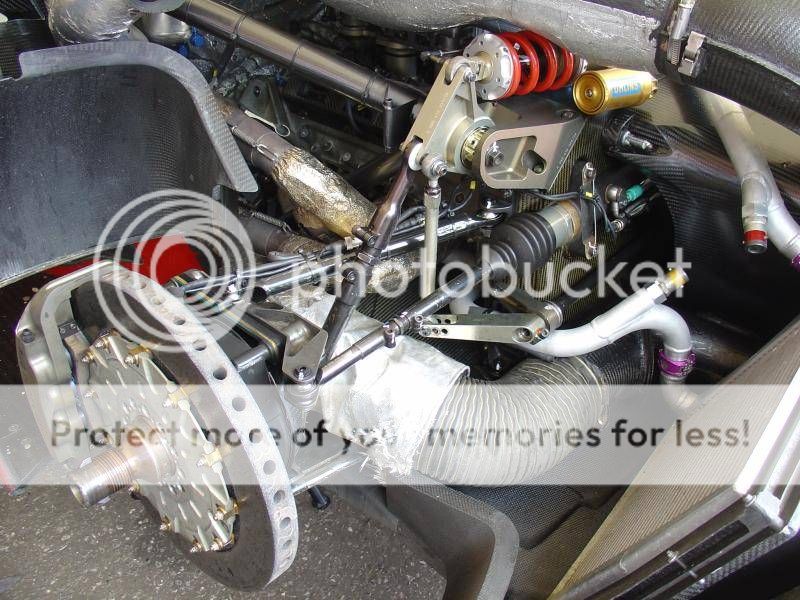
And yes, the pushrod in question in this thread is subject to combined compression and bending.  The bending due to the fact that the rod ends are subject to the of the pivots they are attached to.  If it weren’t for the arc influences the push rod would be subject only to tension and compressive forces.


If we look at the 10mm rod end example that I described earlier we have a push rod that is designed for a dynamic loading of probably 10 kN (2250 pound force).  The rod end probably has a coefficient of friction of 0.1when broken in and if of good quality, slightly higher coefficient if of poorer quality.  This means that the rotating force within the rod end when subject to max dynamic force is 1 kN (225 pound force).  Now this force acts at a radius of about 10mm depending on the design of the rod end.  Thus we are imparting a max bending moment on the push rod of 10 Newton meters (less than 8 foot pounds).


I am glad to see that by post 37 you admit this, “Mostly though it just boils down to an academic argument”.  I think we both can heartedly agree that the bending moment for such an application can be easily ignored.


Oh, and Greg, at Purdue we also were analysing warren truss intermediate  loads with a 12 inch log-log duplex slide rule. Just for old times sake I just pulled out my old K&E with 20 scales and gave it slide back and forth just to remind me.  And yes we would take into full effect the end joint properties that properly applied.  We also ignored those which fell outside of the calculation properties of a slide rule.  My father probably had to do the same.


As proof of the pudding, even to this day I don’t think we have ever had a suspension failure or tube frame failure on any of the 250 race cars we built, (accidents excepted). :clap:


Advertisement

#40 bigleagueslider

bigleagueslider
  • Member

  • 1,235 posts
  • Joined: March 11

Posted 27 March 2014 - 06:02

JB- thanks for the thoughtful reply.


Roark's 1st edition was published in 1938, so anyone doing stress analysis today should be familiar with this text book. And if you have ever worked in the aircraft business, you'd also be familiar with Bruhn's "Analysis and Design of Flight Vehicle Structures". Section A18 of this text deals with the basic instability of columns, and section C4 goes into great detail about round tubes loaded in compression and bending. Bruhn first published this wonderful text over 40 years ago.