Connew... another thread
#1
Posted 14 May 2006 - 09:07
I'll admit that it was not a car I'd heard of, however Marc pointed me in the direction of some photos and Barry Boor who pointed me in the direction of his web site. So far I've managed to put the following together which I hope is a reasonable attempt at the side and plan of the car......
I hope you'll allow my continued progress reports as I build this car
#3
Posted 14 May 2006 - 13:05
#4
Posted 15 May 2006 - 07:37
Yes, please may we have an airbox? That thing took me weeks and weeks to make!
#5
Posted 15 May 2006 - 23:13
Originally posted by FW11B
I hope you'll allow my continued progress reports as I build this car
If you don't continue we will.................................think of something !
#7
Posted 20 May 2006 - 15:53
Originally posted by FW11B
Finally managed to get some time on this one, just the basic structure at the moment, will add some detail, rivits etc later.....
Will include the airbox on the finished model
Very good as far as I can see.
Are you using Inventor or........?
Best: Staffan
#8
Posted 20 May 2006 - 17:47
I'll have a burger with all the trimmings
Just love these tech renderings with all the details
#12
Posted 29 May 2006 - 07:31
#13
Posted 29 May 2006 - 12:29
at least it shows the shape of the wishbones and a bit of detail of the crossmember.
http://img527.images...ewresusp8jy.jpg
#14
Posted 29 May 2006 - 17:33
#16
Posted 30 May 2006 - 04:43
Originally posted by macoran
your master cylinders seem to be up the dash !!
Yeah, I moved them once I'd noticed on this picture.... http://62.149.36.46/...-bin/nobody.jpg
As for the airbox..... difficult as the trumpets will start to poke through the sides if it gets any smaller.
#17
Posted 30 May 2006 - 16:11
Interesting and impressive 3D work, though!
#19
Posted 30 May 2006 - 22:29
I often wonder why designers such as Phillippe (Lotus 72 and Parnelli), Fowell (Amon), Connew and Baldwin (Ensign) went for the (to my eye) overly complex wishbone-to-pullrod 'tripod' anchorage rather than just attaching the pullrod right near the upper wishbone outer apex as Murray would make the norm with the BT44 (although he wasn't the first). Those upper wishbones on the Lotus 72-76-77, Ensign N175-177, the Connew and the AMON AF1 look awfully complex in order to locate the pullrod anchorage point out of the basic plane of the wishbone, for whatever reason. (BTW, I've gone even simpler than the 'standard Murray' set-up on my Aquila FF design by picking the pullrods up directly on the uprights in order to enable non-handed wishbones, but that must be a topic for a non-nostalgia forum so I'll leave it at that for now...)
Advertisement
#20
Posted 30 May 2006 - 22:39
Originally posted by Bonde
...and a very interesting and delicate piece of engineering it is, that rear suspension installation - the workmanship looks good, too. That crossmember looks light and stiff, but also quite complicated the way it was built, airframe style.
It was actually this bit that got me hooked on F1 tech.
#21
Posted 31 May 2006 - 05:43
#22
Posted 31 May 2006 - 22:12
Originally posted by Bonde
At a glance, it looks like the roll centre(s) was too high, with a lot of jacking, and that there was little or even adverse camber compensation at the back (or mayby the member were flexing also.
If you study the pics I posted above and the pic of the underside of this crossmember on Barry Boor's site you'd wonder as I did if the crossmember was actually fixed to anything.
I am sure it flexed a bit....maybe even floated around.
But I still think it is beautiful.
#23
Posted 31 May 2006 - 22:58
I assume you mean this picture from Barry's site (I trust Barry will find this to be Fair Use for research purposes, otherwise I'll remove it!). Here we see it from below:
I've circled-in the four holes where I think this bridge member may have been attached to the cheek lugs on the Hewland 'box. I suspect there may have been local reinforcements at the four holes - the member also hasn't yet had its lower closure panel installed in this shot. Once that is installed, it looks like a pretty efficient piece of structure to me - though PC could probably have made it even more efficient from welded steel sheet rather than riveted aluminium sheet - rivets do cost stiffness compared with continuous welded seams. A good adhesive bond in addition to the rivets does help, though.
I find it interesting that the Connew rear suspension installation was what sparked your interest in F1 technology - how old were you then? I was 12 in 1972 when my motorracing interest was sparked, but for me the whole thing, including the interest in the technology, came all at once - although it would be many more years before I actually understood any of it to any useful extent. Oh well, lots of it I still don't understand and probably never will!
#24
Posted 31 May 2006 - 23:09
The cross member is ribbed quite well, but I feel the distance from the upper set of mounting holes to the upper set of wishbones (rear) mounts is quite a bit greater than the distance between the lower (front) set.
I would expect some twist and torsional differences there.
I am not in total agreement with your rivet/weld comparison
I worked on American style trailers (the aluminium rivetted Smokey the Bandit rigs !) for 20 odd years,and found the welded chassis frames going bust sooner than the rivetted bodies.
See profile.... I am a '49er so I was 23 and had started off a year earlier as a motoring writer for
The Bangkok Post.
Did up quite a collection of Japanese racing magazines there.
#25
Posted 01 June 2006 - 11:03
That top cross-member was our pride and joy! It was beautifully made and was very strong. It did indeed connect to the lugs on the top of the gearbox.
Bonde, I have no problem with any of the pictures from my website being seen - it's only when people try to profit from them without asking that I get a bit miffed.
I will try to get P.C. into this discussion as I am sure he would be very interested to read people's views on his design abilities!
#26
Posted 01 June 2006 - 11:13
#28
Posted 01 June 2006 - 21:25
Still feel you need to look at the length again, seems a bit stretched right now.
#30
Posted 03 June 2006 - 14:39
did you actually model the rear suspension separately ?
#31
Posted 04 June 2006 - 22:00
[B]Livery underway,
BTW will you do a Lec livery one FW ?
#32
Posted 04 June 2006 - 22:34
Interesting observation on the welded vs. rivet trailers...either way, one can always invite fatigue problems if unwary! I do agree that one end of the member is cantilevered quite far, but if the sections are generous enough, that in itself doesn't need to cause problems. There also appears to be some additional stays at the suspension pick-up points, so those should reduce deflections to a useful extent.
Perhaps I was a bit too quick to assume too high roll centres before, as I haven't seen the angular relationship between the upper and lower links - I just remebered seeing some pictures somewhere of the car cornering with the rear wheels displaying really adverse camber and upper suspension links sloping quite steeply downwards toward the wheels. The car also appeared to be jacked up high in the air, and I assumed the suspension links to be convergent toward the chassis, which would indicate high roll-centres. However, the suspension links may have been divergent instead (I don't recall, so I'll have to find that picture again), which instead may have placed the roll-centres low instead. In short, I'm not really sure what was going on!
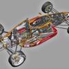
Whether the Connew rear cross-member would have been more efficient (stiffness-to-mass ratio) in welded steel versus riveted aluminium is difficult to determine on the available information, but it is a bit of a hybrid anyway, with the nickel plated welded suspension attachment fittings. Still, it looks great!
Comparing the partially assembled detail photo versus the installed photos, it looks to me like the suspension fittings differ in the photos: They appear to be clevis-like in the detail shot, not so in the installed shots - but I may be mistaken.
#33
Posted 04 June 2006 - 22:52
The rear suspension seems to be slopping all over the place,no roll resistance,
while the front is trying to carry the car through the corner.
If you compare the angle of the top front arocker arms in this shot with those of
the car stationary ( see Barry Boors site ) the outer rocker ( right in this shot)
is as if the car were stationary, while the inside is jacking the asphalt off the track.
#34
Posted 04 June 2006 - 23:16
It does look odd, doesn't it? It looks to me more of a basic suspension geometry problem than one of component flexure, but I can't really make out whether the suspension links converge or diverge toward the chassis, which could make a huge difference roll-centre location-wise.
Component flexure to that extent would, I think, cause so much bump-steer and other nastiness as to probably render the car completely undriveable, even for a keen-to-succeed Francois Migault or David Purley - and it would probably also lead to imminent structural failure.
The camber recovery may not be quite as bad as I first thought - the rims on the outside wheels appear to be fairly upright, but the tyres flex a lot, perhaps making adverse camber on the outside wheels appear more severe than it really is - the inside wheels aren't providing much grip, in spite of the apparently realtively supple suspension (which also suggests high roll centres). But then again, I've been wrong before...
#35
Posted 04 June 2006 - 23:24
I actually suspect the rear roll bar wasn't hooked up.
Look at Francois eyes.......he is wishing the car through the corner.
Also I don't think there is much of a question of adverse camber,
the outside front tyre is grunting !
.......and yes the inner tyre is doing nothing..look at the feathering on
the inside on the top !
#36
Posted 04 June 2006 - 23:45
#37
Posted 05 June 2006 - 00:20
#39
Posted 11 June 2006 - 15:26