Jump to content


Photo
- - - - -

Rotary Valve


  • Please log in to reply
72 replies to this topic

#51 gruntguru

gruntguru
  • Member

  • 7,642 posts
  • Joined: January 09

Posted 12 June 2016 - 23:23

I was thinking of a face seal arrangement - basically a spring-loaded ring around the port, rubbing on the rotary valve. If you look at the BRV, they achieved reliable sealing with straight strips to produce a rectangular boundary - much more difficult.


Manolis could be right. The base dimension for thermal growth (distance between the valve discs) is fairly small. If thermal distortion is not an issue it becomes a question of clearance, material compatibility and carbon build-up.


Advertisement

#52 manolis

manolis
  • Member

  • 935 posts
  • Joined: May 03

Posted 13 June 2016 - 07:16

Hello Gruntguru

The Cross-Bishop rotary valve:

Bishop_vs_PatRoVa.jpg

that caused the change of the F1 rules to forbid the rotary valves, and had already achieved on the dyno – according Mercedes and Ilmor that backed “Bishop” – some 10% more power than the best F1 engines, has several “issues” / problems.

There are two needle-roller bearings at the sides of the cylinder (i.e. at a distance substantially more than 100mm). The needle-roller bearing at the exhaust side cannot help running red-hot. These bearings add their own clearance to the clearance between the rotary valve and the body of the cylinder head; they also bear an “enormous” force equal to the window / port area “connecting the cylinder and the rotary valve” times the cylinder pressure (this force maximizes the worst moment, near the combustion dead center).

The walls of the Bishop rotary valve are, necessarily, thin to provide more port area and maximize the flow capacity (however, at the exhaust side, just under the right bearing in the drawing, the walls gets thicker decreasing the “exhaust area”).

The thin walls are combined with a highly asymmetrical geometry: the inclined separator between the intake and the exhaust sides of the valve is ideal for creating high deformation (flexing and bending and twisting) when a high pressure in the combustion chamber pushes the rotary valve upwards, with the two side bearings providing the necessary reaction force to keep the rotary valve in place.

Worse even, the top wall of the Bishop rotary valve in the drawing is suffering near exhaust gas temperature, while the lower side of the valve is having near ambient air temperature. The rotary valve cannot help bending (thermal distortion).


This drawing is from the “Bishop” patent US7621249 :

US07621249-20091124-D00000.png

The bigger the diameter of the rotary valve, the worse the previous problems / issues (the diameter of the needle roller bearings increases, the thermal distortion worsens, etc).

With a small diameter valve, the port area on the valve and the area of the window / port though which the valve communicates with the cylinder, are about equal, which gives a triangular shape of the valve-time area with slow opening and closing.
In order to get a trapezoidal form of the valve-time area (fast opening and closing, with the “port area” remaining at maximum for several (like, 200) crank degrees), the required diameter of the rotary valve gets big which, apart from the obvious problems, increases the speed of the sealing means as they abut onto the rotary valve periphery (if the diameter of the rotary valve is 25% bigger than the piston stroke, the mean piston speed (and the mean speed of the piston rings on the cylinder liner) equals to the speed of the sealing means on the periphery of the rotary valve) .


Just like in the Coates spherical rotary valves (see the red surface inside the exhaust valve: it exposes a large surface area into the exhaust valve, as a cooler for the exhaust gas):

5327688.jpg?1305294237

The exhaust gas in the Bishop rotary valve finds / sees a huge surface into the exhaust side of the valve and heats it considerably. A significant quantity of exhaust gas remains into the exhaust side of the Bishop valve and cools down by heating the walls, waiting a new, and hotter, quantity of exhaust gas to replace it and continue overheating the walls.

The red-hot separator between the intake side and the exhaust side, inside the Bishop rotary valve, has a large area and heats the fresh charge that waits the window / port to open, it also heats the incoming fresh charge during the suction.


Any leakage from an exhaust spherical rotary valve, or from the exhaust side of the Cross-Bishop rotary valve, is a significant problem (pollution, fuel consumption etc).


Compare all the previous with what happens in the case of the PatRoVa rotary valve.

For instance, think how the PatRoVa handles the hot exhaust gas.
Or better, think what the built-in recycle means, especially in case without sealing means.

The recycle of any leakage at the next suction cycle, allows the operation without sealing means:

At low revs, say at 300rpm of the idling, there is plenty of time for leakage, and the leakage increases; but it is recycled during the next suction cycle (it re-enters the cylinder and gets burned).

As the revs increase, the time for leakage shortens (and proportionally the leakage).
At, say, 3,000 rpm, the time for leakage drops ten times, at 15,000rpm the time for leakage drops 50 times and at 30,000rpm the time for leakage drops 100 times.


With zero friction (no sealing means to rub on moving surfaces, zero total force on the bearings of the rotary valve and zero forces on the timing chain or belt) and a cylinder head rid of lubricant, and a cylinder head with extreme flow capacity, and a cylinder head having no rev limit, things get interesting.

Objections?

Thanks
Manolis Pattakos

Edited by manolis, 13 June 2016 - 12:34.


#53 manolis

manolis
  • Member

  • 935 posts
  • Joined: May 03

Posted 02 July 2016 - 05:15

Hello all.

Here:

PatRoVa_V90_small.gif

it is a V-90 2-cylinder short-stroke PatRoVa rotary valve engine:


Here:

Ducati-899-Superquadro-tech-analysis-3-5

is the Ducati Panigale V-90 engine.

Here:

Ducati-899-Superquadro-tech-analysis-5-5

it is the one cylinder liner of the Ducati Panigale (look at the deep valve pockets on the piston inside the cylinder liner).

Here, the above cylinder liner is shown alone:

Ducati-899-Superquadro-tech-analysis-6-5

Here, the above cylinder is shown from the side:

Ducati-899-Superquadro-tech-analysis-7-5

And here:

686101-horizontal-cylinder-head-valve-dr

they are shown the parts inside each Panigale Desmodromic cylinder head of Ducati (excluding the camshafts).


Here:

PatRoVa_V90_vibr_persp.gif

it is shown the above PatRoVa V-90 from various viewpoints for more details.


Conventionally, between (and “above”) the two halves of the Ducati Panigale casing:

Ducati-899-Superquadro-tech-analysis-4-5

they are secured a pair of Ducati cylinder liners and a pair of Ducati Desmodromic cylinder heads to form the Ducati Panigale engine:


Unconventionally, between the two halves of the Ducati Panigalle casing they can be secured a pair of PatRoVa “cylinder liner / cylinder head” (the cylinder liner together with its cylinder head is one piece, eliminating the gasket and improving the cooling), to form a Ducati PatRoVa V-90 engine which, among others, is:

- more Desmodromic than the Ducati Panigale (there are no restoring springs, at all),

- more high revving than the Ducati Panigale (the cylinder head has not rev limit any longer), for substantially higher specific power,

- way simpler and cheaper than the Ducati Panigale (just count the number of parts).

Thoughts?

Objections?

Thanks
Manolis Pattakos

#54 MatsNorway

MatsNorway
  • Member

  • 2,822 posts
  • Joined: December 09

Posted 03 July 2016 - 10:07

I really do hope you make a ducati engine and revs it for us to see. This is cool. I also like that it is a bolt on head.


#55 manolis

manolis
  • Member

  • 935 posts
  • Joined: May 03

Posted 27 July 2016 - 17:39

Hello all.

For top specific power, a sport motorcycle engine needs to operate
reliably at extreme revs; it also needs extremely oversquare design;
it also needs big diameter valves, high valve lifts and aggressive
valve lift profiles.


Did you ever think how the acceleration and the inertia loads in the
valve train compare with those of the piston?


Quote from the HMEM forum regarding the differences between the loads
in the valve train of a high revving rotary valve engine and of a high
revving conventional poppet valve engine:

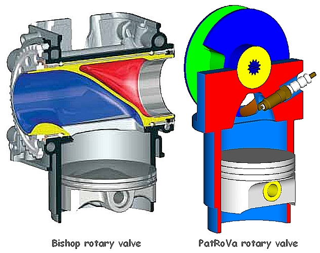
“As regards the inertia loads, comparing the PatRoVa rotary valve with
the poppet valve is like comparing the day with the night.

As a piston, the poppet valve accelerates and decelerates in
synchronization with the crankshaft.

During, say, 240 crank degrees the poppet valve opens and closes
(frequency: 1.5 of the crankshaft frequency).
Its restoring spring has to be strong enough to accelerate the poppet
valve to close following the ramp of the camshaft.

In the Ducati Panigale 1299, the intake valve lift is 16mm for a
piston stroke of 60.8mm. This means that the acceleration of the valve
is (1.5^2)*(16/60.8 ) =0.59 or 59% of the acceleration of the piston.

Ducati_Panigale_valve_train.jpg

Note: the opening and the closing of the valve is far from being pure
sinusoidal;
the acceleration of the piston, due to the limited length of the
connecting rod, is not sinusoidal , too.
But in the lump sum the acceleration of the valve is more than half of
the acceleration of the piston.

With the intake valve weighing 46.8gr (Ducati Panigalw 1299), the
overall reciprocating “valve mass” is about 100gr (it is the valve
mass plus half of the spring mass, plus a part of the mass of any
linkage like, say, the cam follower).

At 11,500rpm the acceleration of the piston of the Panigale is about
5,600g; according the previous, the acceleration of the inlet poppet
valve of the Panigale is more than 2,800g.

This means that the spring has to be capable to apply a restoring
force of at least 280Kp (about 600lb) to the valve (actually more, for
safety), otherwise the valve cannot follow the cam lobe. This means
that the camlobe has to apply to the valve / valve spring an even
stronger force (necessary for the acceleration of the valve / valve
spring and for the compression of the valve spring) in order the valve
to move as it moves.

For the motion of the conventional poppet valves they are required
extreme forces (which means stress on the parts involved (including
the timing chain or belt), friction, wear, cost etc.)
Ducati solved partially the problem by eliminating the restoring valve
springs (Desmodromic cylinder heads: the valves not only open
positively – as in the conventional valve trains – but they also close
positively, without the need of restoring springs).”

End of Quote.


Interesting?


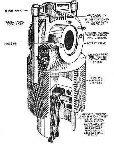
Quote from the same discussion about the time required for the
combustion in a model (RC) PatRoVa rotary valve engine:


” The Ducati Panigale 1299 has 116mm bore, 60.8mm stroke and runs
reliably till 11,500rpm of the rev limiter.

In the 24.8mm bore x 13mm stroke (6.28cc) PatRoVa model engine (same
bore to stroke ratio with the Ducati):

PatRoVa_model_short_stroke.gif

PatRoVa_model_short_stroke_section.gif

PatRoVa_model_short_stroke_valve_cover.g

the flame has to travel a 116/24.8=4.7 times smaller distance.

Provided the flame front propagates at the same rate (speed) in the
Panigale 1299 and in the PatRoVa model engine, the second burns the
mixture until at least 11,500*4.7=53,800rpm

Actually, the flame in the Ducati Panigale extends slower than the
flame in the PatRoVa model engine because the shape of the combustion
chamber of the first is not good: it is a thin disk (116mm diameter,
5.24 mm average height for 12.6:1 compression ratio), with deep valve
pockets on the piston crown and necessarily abnormal shape of
combustion chamber walls.
In the one case the flame extends at the two only dimensions (thin
disk), while in the second case, wherein almost all the mixture is
concentrated into the chamber formed between the two disks of the
rotary valve (the clearance between the flat piston crown and the
cylinder head is quite small: the limitation is to avoid the
piston-cylinder head collision at high revs), the flame extends in
three dimensions and proceeds faster with lower thermal loss.

So, as regards the combustion, 50,000rpm is OK for the (above)
oversquare PatRoVa model engine.”

End of Quote.


Objections?

Thanks
Manolis Pattakos

Edited by manolis, 27 July 2016 - 17:46.


#56 manolis

manolis
  • Member

  • 935 posts
  • Joined: May 03

Posted 16 August 2016 - 13:39

Hello.

Here is an animation of the short-stroke PatRoVa model engine (13mm stroke, 24.8mm bore):

PatRoVa_finnel_ports.gif

It has funnel exhaust ports and inner cooling (by the inertia of the exhaust gas) of the rotary valve exhaust port and of the exhaust passageways in the cylinder head (think how).

And here is a couple of stereoscopic animations of the above short-stroke PatRoVa model engine (13mm stroke, 24.8mm bore):

PatRoVa_model_engine_transparent_STE.gif

PatRoVa_model_engine_transparent_STE_orb

Thoughts?

Thanks
Manolis Pattakos

#57 gruntguru

gruntguru
  • Member

  • 7,642 posts
  • Joined: January 09

Posted 18 August 2016 - 01:07

Hi Manolis.

Here is another potential benefit of your rotary valve design. I was looking at the Nissan VCR concept and thinking that an even higher CR (the Nissan ranges from 8 to 14) might be useful at light loads (especially on a NA version). Of course the pent-roof chamber design has severe limitations on CR with normal B/S ratios. With no valves to clear the piston-crown and a compact combustion chamber, your rotary valve cylinder head could still offer a clean combustion chamber at much higher CRs - perhaps as high as 20:1.


20:1 sounds high but at light load and possibly Atkinson LIVC, 20:1 would be a useful number.


Edited by gruntguru, 18 August 2016 - 01:08.


#58 manolis

manolis
  • Member

  • 935 posts
  • Joined: May 03

Posted 18 August 2016 - 13:54

Hello Gruntguru.

You write:
“Here is another potential benefit of your rotary valve design. I was looking at the Nissan VCR concept and thinking that an even higher CR (the Nissan ranges from 8 to 14) might be useful at light loads (especially on a NA version). Of course the pent-roof chamber design has severe limitations on CR with normal B/S ratios. With no valves to clear the piston-crown and a compact combustion chamber, your rotary valve cylinder head could still offer a clean combustion chamber at much higher CRs - perhaps as high as 20:1.
20:1 sounds high but at light load and possibly Atkinson LIVC, 20:1 would be a useful number.”


According “Bishop” (Cross type, F1 rotary valve):
“The F1 single cylinder engine ran compression ratios as high as 17:1 using standard F1 fuels before settling on 15.3:1 as optimum. No evidence of knock has ever been observed and this is thought to arise from an absence of any hot surfaces in the combustion chamber . . .”


Reasonably they settled on the 15.3:1 compression ratio because with this compression ratio they were achieving more power than with higher compression ratios.


With the PatRoVa rotary valve, a 20:1 compression ratio seems feasible, but at full load the resulting forces on the piston / connecting-rod / crankshaft / cylinder-liner and the relative friction / wear will be a problem unless the engine runs on Atkinson – Miller cycle (over-expansion), for instance as the Toyota PRIUS but with a bigger percentage of the charge entered the cylinder returning back to the intake manifold before the start of the actual compression (LIVC).

With the proper design of the PatRoVa rotary valve / cylinder head, during the initial part of the compression stroke half of the entered air or mixture can exit from the cylinder and return back to the intake manifold, so that a “theoretical” compression ratio of 20:1 drops to an actual compression ratio of about 10:1.

The engine may seem under-powered, however if the revs increase a lot (the PatRoVa cylinder head has not a rev limit), the engine can provide a lot of power.

This way the pumping loss is eliminated (there is not sub-pressure in the intake manifold).

This way the Brake Thermal Efficiency (BTE) of the spark ignition engine at partial load can prove better than the BTE of the Diesels at the same partial load.

And if the BTE is so good at partial loads, the hybrids become meaningless (now the hybrids exploit the inefficiency of the spark ignition engine at light / partial loads).


Theoretically the PatRoVa seems pretty good.

In practice we need to make a competitive prototype, preferably by modifying a Ducati Panigale to give the stock Panigale’s a competition.

Unfortunately, till now no Panigale owner has been found with broken heads and the will to take part in the modification / tests.

Thanks
Manolis Pattakos

#59 gruntguru

gruntguru
  • Member

  • 7,642 posts
  • Joined: January 09

Posted 19 August 2016 - 08:41

Reasonably they settled on the 15.3:1 compression ratio because with this compression ratio they were achieving more power than with higher compression ratios.

With the PatRoVa rotary valve, a 20:1 compression ratio seems feasible, but at full load the resulting forces on the piston / connecting-rod / crankshaft / cylinder-liner and the relative friction / wear will be a problem unless the engine runs on Atkinson – Miller cycle (over-expansion), for instance as the Toyota PRIUS but with a bigger percentage of the charge entered the cylinder returning back to the intake manifold before the start of the actual compression (LIVC).

With the proper design of the PatRoVa rotary valve / cylinder head, during the initial part of the compression stroke half of the entered air or mixture can exit from the cylinder and return back to the intake manifold, so that a “theoretical” compression ratio of 20:1 drops to an actual compression ratio of about 10:1.

I think you missed my point. I was referring to VCR technology and the need for ultra-high "geometric" CR at part load. Poppet valve engines simply cannot achieve such high CR without compromising one of - BS ratio, valve timing, combustion chamber geometry etc etc.


So the Patrova combined with VCR has a lot going for it.


Advertisement

#60 manolis

manolis
  • Member

  • 935 posts
  • Joined: May 03

Posted 19 August 2016 - 13:59

Hello Gruntguru.

You write:
“I think you missed my point. I was referring to VCR technology and the need for ultra-high "geometric" CR at part load. Poppet valve engines simply cannot achieve such high CR without compromising one of - BS ratio, valve timing, combustion chamber geometry etc etc.
So the Patrova combined with VCR has a lot going for it.”


1. At a first approach I cannot disagree that the PatRoVa combined with VCR has a lot going for it.

And a better VCR than Nissan’s is the PatHead VCR:

vcr13.gif

(more at http://www.pattakon....pattakonVCR.htm)

VCR_PatHead_Vee.gif

Why the PatHead VCR is better and fits better with the PatRoVa?

Because it leaves the basic mechanism (the crankshaft, the connecting rods and the pistons) unaffected: the dynamic parts of the basic mechanism are fully conventional and move, at all compression ratios, the same conventional way.

What in case the engine of the Nissan Infinity undergoes an over-revving (say during braking with the engine)? Are all these links strong enough to withstand the loads?

On the other hand, and no matter how simple and compact and lightweight and robust it is, we cannot put the PatHead VCR in mass production while Nissan can put in mass production their own VCR (I can’t see where it differs from Honda’s VCR, but this is another story).


2. At a second approach I disagree that the PatRoVa combined with VCR has a lot going for it.

What I think is that the PatRoVa needs not a VCR because it can operate, either at full or at partial load, at substantially higher compression ratios than the poppet valve engines.

Bishop (Cross-type rotary valves which caused the change of the F1 rules to ban the rotary valves from F1) claims that with 17:1 compression ratio and full load they never noticed knocking.

The PatRoVa has no reason to be worse in knocking resistance than the Bishop rotary valve. The temperature of the walls around the compressed charge is more uniform in the case of the PatRoVa, while the combustion chamber is more concentrated and smooth.

So let’s suppose that the PatRoVa can run at full load with 16:1 compression ratio.

The Infinity needs a VCR to lower the compression ratio because otherwise it knocks. At heavy load it cannot keep the high (14:1) compression ratio used at partial loads, so it lowers it to avoid the knocking.
At full load the compression ratio drops to the lowest (8:1).


Take now the case of the PatRoVa:

16:1 compression ratio is OK for full load (and is substantially higher than the maximum 14:1 compression ratio of the Infinity VCR).

16:1 is OK for the intermediate loads.

16:1 is OK for light load and for idling, too.

So what is the reason of using a VCR with the PatRoVa?


If it is not simpler, if it cannot rev higher, if it is not more compact, if it is not more lightweight, if it is not more powerful, if it is not more torquie, if it is not more fuel efficient and clean . . . that is if it is not the winner everywhere it is dead from the beginning.
But if the Moto-GP racers or the Formula1 racers etc know that out on the roads there is something more powerful . . .


By the way, here is a V-2 PatRoVa model RC engine:

PatRoVa_V2_model_engine_STE.gif

bore 24.8mm,
stroke 13mm (i.e. same bore to stroke ratio with the Ducati Panigale 1299 which has 116mm bore and 60.8mm stroke),
total capacity 12.5cc,
rev limit at 50,000rpm (21.7m/sec mean piston speed).

With the secondary balance web (slim orange) at the free end of the crankshaft, the “vibration free quality” of this engine is the same with the vibration free quality of the big Ducati Panigale.

The one connecting rod is red, the other is blue. They share the same crankpin.

There is one only, common for both cylinders, timing belt.

There is one only crankpin (it is of bigger diameter than in the single cylinder).

The crankshaft is rotatably mounted on the casing (green part) by two roller bearings. The roller bearing beside the main balance web (orange, with the crankpin on it) is the strong one.

The casing (the green part with the cooling fins) is a single piece part.


Thanks
Manolis Pattakos

#61 manolis

manolis
  • Member

  • 935 posts
  • Joined: May 03

Posted 24 August 2016 - 03:37

Hello all.


Wankel_model_OS.gif


PatRoVa sealing versus Wankel sealing


Let's compare the sealing (and so the gas leakage) of a Wankel Rotary RC engine (say, the 49PI of the OS) with the single cylinder short stroke PatRoVa:

According OS, their 49PI Wankel rotary has:
4.97cc capacity (per chamber),
1.1hp/17,000rpm,
practical range: 2,500-18,000rpm,
(weight: 450gr).

According OS manuals / drawings, the height of the rotor (piston) along the axis of the power shaft is estimated at 15mm, while the total periphery of the triangular rotor is estimated at 120mm (40mm between each pair of apexes).

So, each chamber of the model Wankel rotary uses for its sealing two apex seals and two pairs of flat surfaces (the one on the side of the rotor, the other on the casing) each having 40mm length. So, besides the two apex seals, each chamber of the above Wankel model engine leaks from a periphery of 40+40=80mm. The leakage through these two long slits (80mm total length) is limited using a small clearance between the sides of the rotor and the flat surface of the “side covers” of the combustion chamber.


The PatRoVa short stroke model engine has:
6.28cc capacity,
13mm stroke,
and 24.8mm bore.
The periphery of each window of the PatRoVa model engine is 30mm, which means the total “sealing” periphery is 30+30=60mm for a 6.28cc capacity.


At the same revs, say 15,000rpm of the crankshaft and of the power shaft, the time interval for leakage is 50% longer in the case of the Wankel: while the reciprocating piston of the PatRoVa needs 180 crank degrees to go from the maximum volume in the combustion chamber to the minimum volume in the combustion chamber (actually from the BDC to the TDC), the power shaft of the Wankel needs to rotate for 270 degrees in order the volume in the combustion chamber to go from its maximum to its minimum.


The PatRoVa can feature a several times smaller clearance between the inner flat surfaces of the two disks and the lips of the chamber ports as compared to the required / necessary clearance between the flat sides of the rotor and the flat side covers of the casing.
Think why.
For the sake of the calculations let’s suppose the PatRoVa uses the same clearance with the Wankel rotary.

The absolute leakage in the Wankel model engine through the side slits is (80mm/60mm)*1.5=2 , i.e. it is double than in the PatRoVa model engine (the 1.5 is due to the 50% longer time the high pressure is maintained into the Wankel’s combustion chamber).

The relative leakage is even worse: 2*(6.28cc/4.97cc)=2.5. This means that if a percentage of 25% of the charge in a combustion chamber of the Wankel model engine leaks from the sides of the rotor, this percentage drops to 10% in the case of the PatRoVa.

(From another viewpoint: for the same percentage of leaked gas, the PatRoVa can run 2.5 times slower than the Wankel model. For instance, the PatRoVa running at 1,000rpm has the same leakage with the Wankel running at 2,500rpm (the lower practical rpm according OS)).


But there is more:

The PatRoVa has the same bore to stroke ratio with the Ducati Panigale 1299 and even freer breathing (the ratio of the total chamber port area to the piston area is bigger than in the Panigale).
The Panigale (1300cc, two cylinders in Vee 90 degrees) makes its peak power at 10,500rpm (21,3m/sec mean piston speed). Reasonably the PatRoVa model engine will make some 4.7hp at 50,000rpm (21.7m/sec mean piston speed).

At 50,000rpm the time for leakage is 50,000/17,000 = 2.94 times less than at 17,000rp (where the Wankel model engine makes its peak power).

And because 2.94*2.5=7.35, if at 17,000rpm the 15% of the charge in a combustion chamber of the Wankel model engine leaks from the side “slits”, this percentage will drop to only 2% in the case of the PatRoVa model engine.


And there is more:

While the width of the combustion chamber of the PatRoVa (i.e. the distance between the two disks of the rotary valve) is less than 9mm, the rotor height (along the rotation axis of the power shaft of the Wankel) is 15mm, i.e. the one width is 60% bigger than the other.

This means that the necessary clearances in the Wankel need to be some 60% bigger than the clearances in the cylinder head of the PatRoVa.
Actually they are way bigger because of the architecture of the Wankel (see how the two side plates are secured to each other) and of the big temperature differences along the parts / surfaces that participate in the side sealing of the Wankel.

To be noted: a double clearance allows a way more than double leakage.


According the previous analysis:

The sealing quality in the PatRoVa model engine is many times better than in the existing Wankel model engines.


Objections?

Thanks
Manolis Pattakos

#62 manolis

manolis
  • Member

  • 935 posts
  • Joined: May 03

Posted 11 April 2017 - 04:24

Hello all.

Quote from http://www.cycleworl...h-kevin-cameron

“Benefits Of Pneumatic Valves

MotoGP rookie Jack Miller is feeling the effects of what his Honda engine “wants.”
By Kevin Cameron posted Nov 29th, 2014 at 10:00pm

I noted that MotoGP rookie Jack Miller, describing his recent test at Malaysia’s Sepang International Circuit, spoke of the “smoother, more controlled power delivery” of the pneumatic-valve Honda RC213V-RS.

I like to emphasize that pneumatic springs have value other than the raw ability to reach high rpm. What pneumatics do best is make the valves follow short-duration, high-lift cams that metal springs cannot. Engines with metal springs must be given longer duration and reduced lift if they are to reach competitive rpm, and both of these changes compromise performance. Yamaha was behind this 8-ball in 2006.
Increasing duration (valve open time) to give metal springs longer time in which to accelerate/decelerate valves has two harmful effects:

1) Keeping the intakes open longer after bottom center (BDC) allows the piston, rising on its compression stroke at low- and mid-rpm, to push out part of the fresh charge it has just pumped in (at higher revs, the inertia of the faster-moving intake flow prevents this). Less charge retained in the cylinder equals less engine torque.

2) Beginning to open the intakes earlier before top center (TDC) extends the overlap period during which the exhausts are not yet closed yet the intakes have begun to open. This creates a window through which exhaust pipe waves act to create a deep flat spot just before peak torque. (This occurs at mid-rpm when the returning pipe wave is positive and pushes exhaust gas back into the cylinder and possibly even fills the intake pipes and airbox with exhaust. The torque-weakening effect of all this exhaust gas in the cylinder produces the flat spot.)

The result of the above is both weak torque in the low- and midrange, and a steeper, more abrupt torque rise from the flat spot to the torque peak just above it. The rider finds it tricky to exit corners smoothly when his engine has to accelerate through such a steep torque rise.

The third effect is reduced intake flow even on top end, caused by the reduction in valve lift required if a metal-spring engine is to reach higher revs.
In sum, what pneumatic springs really do is allow valve motion to more closely approximate what the engine and its airflow “want.”

END OF QUOTE


It seems the poppet valves have reached their limit in the MotoGP racing engines.

For even more power at higher revs, they are required even bigger valves and even longer valve lifts.

The metal valve springs cannot follow.

The Desmo of Ducati has reached its limits.

The pneumatic valve springs are better, however the inertia loads increase with rpm square, they also increase proportionally with the valve lift, they also increase proportionally with the mass of the valve (which increases with the cube of the valve diameter).


Here is a PatRoVa Rotary valve with tapered disks (the exhaust exits from the centers):

PatRoVa_Taper_4.gif

PatRoVa_Taper_2.gif

PatRoVa_Taper_3B.gif

and a stereoscopic animation (instructions on how to see it at http://www.pattakon....Stereoscopy.htm )

PatRoVa_Taper_STE.gif


Thoughts?

Objections?

Thanks
Manolis Pattakos

#63 manolis

manolis
  • Member

  • 935 posts
  • Joined: May 03

Posted 25 May 2017 - 04:20

Hello all.

According an Issue Notice of the US Patent and Trademark Office:

PatRoVa_US_Patent_Issue.gif

a patent is granted for the PatRoVa Rotary Valve.

The patent number is US9,677,434.

Thanks
Manolis Pattakos

#64 manolis

manolis
  • Member

  • 935 posts
  • Joined: May 03

Posted 13 June 2017 - 15:07

Hello all.

Today the US-PTO published the USA patent granted for the PatRoVa rotary valve.

Here is the link:

http://patft.uspto.g...4&RS=PN/9677434

Thanks
Manolis Pattakos

#65 gruntguru

gruntguru
  • Member

  • 7,642 posts
  • Joined: January 09

Posted 13 June 2017 - 22:37

Congratulations Manolis.

It didn't grab me at first but the PatRoVa is growing on me.


#66 Kelpiecross

Kelpiecross
  • Member

  • 1,730 posts
  • Joined: October 10

Posted 14 June 2017 - 02:31


I still think that there would be sealing problems. Maybe an oil feed to the hot exhaust side to produce a constant carbon build up as sealing?
Pleased you are back Manny - there is only so much discussion about driverless car and VW emissions a person can take.

#67 manolis

manolis
  • Member

  • 935 posts
  • Joined: May 03

Posted 15 June 2017 - 03:39

Hello Kelpiecross.

You write:
“I still think that there would be sealing problems. Maybe an oil feed to the hot exhaust side to produce a constant carbon build up as sealing?”


There is not hot exhaust side in the combustion chamber of the PatRoVa.

Quote from http://www.pattakon....konPatRoVa.htm:

“The combustion chamber is rid of hot spots (like, for instance, the hot exhaust poppet valves of the conventional engines, or like the hot chamber ports of the state-of-the-art exhaust rotary valves). Every point of the combustion chamber is equally related with the intake and with the exhaust. On this reasoning the compression ratio can further increase.”

End of Quote.


The above means, among others, that the combustion chamber can have a substantially higher average temperature than in a conventional engine, having at the same time a substantially lower local peak temperature on its walls.

The compact combustion chamber enables faster combustion (more “constant volume” combustion) further increasing the allowable wall temperature.

These, in turn, mean that less cooling is required.
The air-cooling seems OK for the cylinder head of the PatRoVa.
Worth to mention here: some boxers (of BMW, of Rotax, of Porsche etc) have liquid cooled cylinderheads and aircooled cylinders.

Less cooling means reduced thermal loss; wchich, in turn, means more mechanical power on the crankshaft, higher BTE (Brake Thermal Efficiency) and lower BSFC (Brake Specific Fuel COnsumption).


You also write:
“Pleased you are back Manny - there is only so much discussion about driverless car and VW emissions a person can take.”

Aren’t all the previous interesting topics for technical discussion?

PatRoVa_Taper_6.gif

Thanks
Manolis Pattakos

Edited by manolis, 15 June 2017 - 03:45.


#68 malbear

malbear
  • Member

  • 309 posts
  • Joined: September 02

Posted 17 June 2017 - 13:27

“The combustion chamber is rid of hot spots (like, for instance, the hot exhaust poppet valves of the conventional engines, or like the hot chamber ports of the state-of-the-art exhaust rotary valves). Every point of the combustion chamber is equally related with the intake and with the exhaust. On this reasoning the compression ratio can further increase.”

End of Quote.


The above means, among others, that the combustion chamber can have a substantially higher average temperature than in a conventional engine, having at the same time a substantially lower local peak temperature on its walls.

The compact combustion chamber enables faster combustion (more “constant volume” combustion) further increasing the allowable wall temperature.

These, in turn, mean that less cooling is required.


I agree 


#69 manolis

manolis
  • Member

  • 935 posts
  • Joined: May 03

Posted 04 December 2019 - 12:42

Hello all.
 
In his Internet Museum at http://www.douglas-s...ValveIC.htm#crs Douglas Self writes: 
 
“The Cross rotary valve: circa 1935
The "reaction bridge" shown in the picture at left absorbs the upward forces on the horizontal valve assembly, and is supposed to have reduced the gas forces on the actual valve. At the moment I'm not quite sure I understand how it worked.
 
Cross_Rotary_Valve_Reaction_Bridge.jpg


The “reaction bridge” of Cross “works” as follows:
 
 
The top half of the cylinder head is firmly secured to the crankcase by the “bridge” and the two strong pillars, i.e. the top half cylinder head and the crankcase form a rigid body.
 
The lower half of the cylinder head, together with the cylinder (the piece with the horizontal cooling fins) comprise another rigid body which is free to play for, say, 0.25mm (0.01”) up and down relative to the crankcase (the “spring” seal at the bottom of the cylinder pushes upwards the cylinder and the lower half of the cylinder head) .
 
The “horizontally” arranged cylindrical rotary valve (the typical Cross rotary valve) abuts, at its top side, on the upper half of the cylinder head.
The body comprising the cylinder and the lower half of the cylinder head abuts on the lower half of the rotary valve.
 
For as long as the pressure inside the cylinder (above the piston) is small (which happens during the induction cycle, during the exhaust cycle, and during most of the compression cycle, i.e. during some 70% of the total time) the cylinder with the lower half of the cylinder head are pushed upwards by a weak force; the only who prevents the cylinder with the lower half of the cylinder head to move upwards is the lower half of the rotary valve whereon they abut; and the only who supports the rotary valve from not going upwards it the upper half of the cylinder head whereon it abuts. 
So, the weak force mentioned passes to the rotary valve, then to the upper half of the cylinder head and, through the pillars, to the crankcase.
 
During the last part of the compression cycle and during the combustion and expansion cycle, the high pressure in the cylinder translates into a heavy force onto the “cylinder and lower half of the cylinder head”, and another heavy force onto the part of the rotary valve surface whereon the high pressure gas acts through the “window” of the combustion chamber. The sum of these two heavy forces equals to the force the gas applies to the piston top. The rotary valve passes this total force to the upper half of the cylinder head whereon it abuts.
 
I.e. during the last part of the compression and during the combustion – expansion the rotary valve receives a strong force that deforms / flexes it, and it passes all of it to the upper half of the cylinder head.
 
But this heavy loading happens only during the, say, 30% of the total time. For the rest 70% of the time the rotary valve runs almost free of loads (no need for heavy preloading).
 
But even for the 30% during which the rotary valve undergoes strong forces, the lighter the load the engine runs, the lighter the forces on the rotary valve. 
 
This way Cross achieved to reduce the, otherwise, necessary heavy preloading between the rotary valve on its “bearings”, improving the reliability and longevity, and reducing the specific lube consumption.
 
One side effect is the “side support” of the “free” / “sliding” cylinder in order to receive the thrust loads from the piston and the leaning connecting rod.
 
Another side effect is the significant increase of the maximum force acting on the rotary valve and its bearings: it equals to the gas pressure times the piston area. 
In the conventional Cross rotary design, the force on the rotary valve and its bearings equals to the gas pressure times the “window” area. 
 
According the previous analysis, at heavy loads (wide open throttle) the "reaction bridge" creates more problems than it solves.
 
 
Note: the “self-adjusting reaction bridge”, top-right in the image, may be used to reduce the “hammering” from the “oscillating cylinder”.


In the same “Internet-Museum” of DOuglas Self,, at http://www.douglas-s...ValveIC.htm#now it writes:
 

“Another contemporary concept is the PatRoVa rotary valve. Like the Cross design it balances out the forces acting on the rotating valve.”


While the bearings of the Cross Rotary Valve receive all the gas pressure acting on the piston, the PatRoVa rotary valve bearings:   
 
PatRoVa_Taper_3B.gif
 
run permanently unloaded as the following quote from https://www.pattakon...akonPatRoVa.htm explains:
 
 
Heavy, but internally counterbalanced, loads
 
The high pressure inside the cylinder "sees", though the chamber ports, the two fronts and loads them heavily. The rotary valve receives the two strong forces. With the one force counterbalancing the other (through the body of the rotary valve), the overall "pressure" force acting on the rotary valve is from small to zero, leaving its bearings unloaded.
 
That is, in order to bear the heavy forces applied by the cylinder pressure on its fronts, the PatRoVa "disk rotary valve" needs not the support of a bearing and avoids, this way, both: the inevitable clearance / "play" a bearing introduces and the associated friction / wear.
 
What the rotary valve does need is a very strong "body" to "connect" the oppositely acting fronts; so strong that the heavy loads applied on the fronts to cause no more than an insignificant deformation of the rotary valve and thereby to keep into the required strict limits the clearance between the chamber ports and the rotary valve fronts (wherein the sealing happens).
 
 
PatRoVa_photo11F.jpg
 
open_end_wrench.jpg
 
 
I communicated a few times with Douglas Self asking him to correct his "description" for the the PatRoVa Rotary Valve in his Internet Museum, but  . . .
 
 
Thanks
Manolis Pattakos

Edited by manolis, 04 December 2019 - 12:45.


#70 Kelpiecross

Kelpiecross
  • Member

  • 1,730 posts
  • Joined: October 10

Posted 07 December 2019 - 12:55

Manny - what is your argument  with Self?  - he does agree that your forces are balanced.    


#71 manolis

manolis
  • Member

  • 935 posts
  • Joined: May 03

Posted 08 December 2019 - 06:49

Hello Kelpiecross.


Here is what Douglas Self writes in his Internet Museum:


The "reaction bridge" (of Cross) absorbs the upward forces on the horizontal valve assembly, and is supposed to have reduced the gas forces on the actual valve. At the moment I'm not quite sure I understand how it worked.


and later, in the same page:


Another contemporary concept is the PatRoVa rotary valve. Like the Cross design it balances out the forces acting on the rotating valve.


Both arguments are wrong.


As my last post analysis explains, Cross’ “reaction bridge” does not really absorb the upwards forces on the horizontal valve assembly.


What the “reaction bridge” really does, is that it reduces the “upwards forces on the horizontal valve assembly” during the low pressure portion of the cycle (induction stroke, exhaust stroke and a part of the compression stroke), while it substantially increases the “upwards forces on the horizontal valve assembly” during the high pressure portion of the cycle (compression stroke and power stroke).


An example:


Suppose that the cylinder bore is 80mm (which gives a piston area of 50cm2), suppose also that the “window” at the bottom of the cylinder head (through this window the gas in the cylinder “sees” the rotary valve) is a rectangle 40mm x 40mm, (which means a valve area of 16cm2, which is a large valve area), suppose also that the maximum combustion pressure is 50bar.


Without the “reaction bridge”, the maximum force on the rotary valve (and on its bearings) is 16cm2 x 50bar = 800Kp = 8,000Nt.


With the “reaction bridge”, the maximum force on the rotary valve (and on its bearings) is 50cm2 x 50bar = 2,500Kp = 25,000Nt, i.e. more than 3 times heavier.


I.e. the reaction-bridge “solution” of Cross is not a good one, unless his rotary valve engine is to work only at partial loads. At wide open throttle (heavy load), the rotary valve and its bearings undergo heavy “unbalanced” upwards forces that cause friction and wear and increase the lube consumption.  


On the other hand, without the reaction-bridge “solution”, the rotary valve of Cross needs a heavy preloading, which causes friction loss and wear (especially during the “low pressure” portion of the cycle, which counts for some 70% of the total time).


On one hand, Douglas Self writes that he does get how the Cross reaction-bridge balances the upwards forces on the rotary valve,

on the other hand he writes that the PatRoVa rotary valve, LIKE THE CROSS rotary valve, balances the upwards forces.  


Contrary to the Cross reaction-bridge rotary valve,

the PatRoVa rotary valve architecture does balance the forces (on the rotary valve and its bearings) permanently (i.e. during the induction stroke and the compression stroke and the power stroke and the exhaust stroke), and at all revs, and all loads (from closed throttle (idling) to wide open throttle / full load).


The question was:


Is there another rotary valve that, as the PatRoVa rotary valve, can really balance the forces caused by the gas pressure on it and on its bearings?


Say, like:


PatRoVa_compression.jpg


where the pressure inside the cylinder is 12bar (manual cranking) and the PatRoVa Rotary Valve seats freely (without any bearings) on the cylinder head (if you want to lift it, you have to pull it with a force as heavy as its weight, say 3lb).


Thanks

Manolis Pattakos


#72 Kelpiecross

Kelpiecross
  • Member

  • 1,730 posts
  • Joined: October 10

Posted 10 December 2019 - 09:34

 Manny -  As far as I can tell - there is no other rotary valve that balances the gas forces etc. like the PatRover.  And for this reason I think the PR is probably the only rotary valve arrangement (that I am aware of) that could ever be developed into  a workable, useable valve system.  


 Having said that: -  I think the port area is a little restricted.

                                The   passage leading into (or out of)  the port is somewhat cramped and has to turn at a sharp  angle to reach the outside of the head.  

                                 I don't think it could ever compete with the traditional  cam-and-poppet-valve systems - mainly because they are so well-developed and reliable now.

                                 Also - I think even though the clearances are very small - it would need some form of sliding seal around the port.

                                 And - the combustion chamber is a bit of a funny shape.    


 However - I think the perfect application for the PR would be a  two-stroke engine using the PR as the intake and  a uniflow system for the exhaust.  One thing a  cam-and-poppet etc.  can't do very well is run at  crankshaft speed (as it would need to for a two-stroke) - but the PR could run at crankshaft speed easily.  If only using the PR for intake both sides could be used  giving double the port area and less-restrictive passages.  And the cooler temperatures of the inlet (compared to the exhaust side)  would also make the PR more practical.

 By varying the alignment of the sides you could also have a form of variable port opening duration.  

 I think you could make a very useful engine using the PR and etc. above  (and in fact I might steal the idea).  


Edited by Kelpiecross, 10 December 2019 - 11:23.


#73 manolis

manolis
  • Member

  • 935 posts
  • Joined: May 03

Posted 11 December 2019 - 04:49

Hello Kelpiecross.


You write:

“As far as I can tell - there is no other rotary valve that balances the gas forces etc. like the PatRover.  And for this reason I think the PR is probably the only rotary valve arrangement (that I am aware of) that could ever be developed into  a workable, useable valve system. “


Thanks.


In comparison to your comment,

Douglas Self in his Internet Museum,

in some 70 “pages” of text (with some 80 photos / drawings),

presents the various rotary-valve designs and the attempts to put the rotary valves in the internal combustion engines (http://www.douglas-s...taryValveIC.htm );

his only reference to the PatRoVa rotary valve is a single line of text:


PatRoVa_Douglas_Self.png


and even this single line is not correct.


You also write:

“I think you could make a very useful engine using the PR and etc. above  (and in fact I might steal the idea).”


Be my guest.


Thanks

Manolis Pattakos