Hello Kelpiecross.
You write:
"You demonstrated in this video the system appears to work well mechanically - maybe it is time you made a simple test rig to discover just how much thrust it can produce? Endless speculation and calculation about the system's performance is not really enough."
In the youtube video you mention, it is shown the OPRE engine (Opposed piston Pulling Rod Engine, more details at
http://www.pattakon....attakonOPRE.htm )
It is a direct injection Diesel through scavenging with “four-stroke-like lubrication and built-in scavenging pumps.
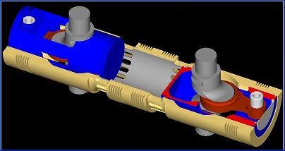
It is the basis for an OPRE Portable Flyer:
that requires unconventional wide-Vee propellers (that require special materials and manufacturing).
It is a proof-of-concept low-cost prototype (for instance, its injection system comes from a low cost 400cc 4-stroke Chinese electric generator, its one-way valves are made of steel strip by hand, etc).
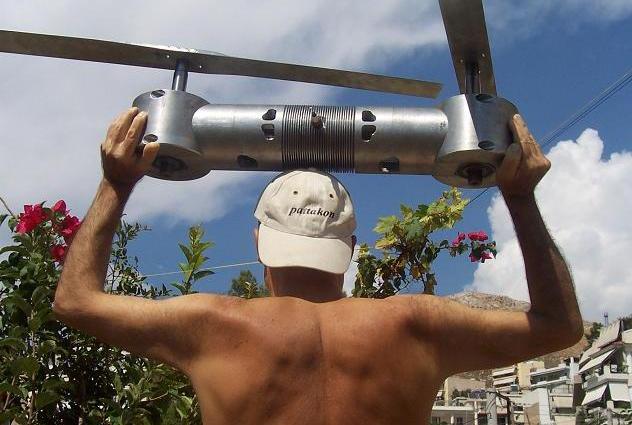
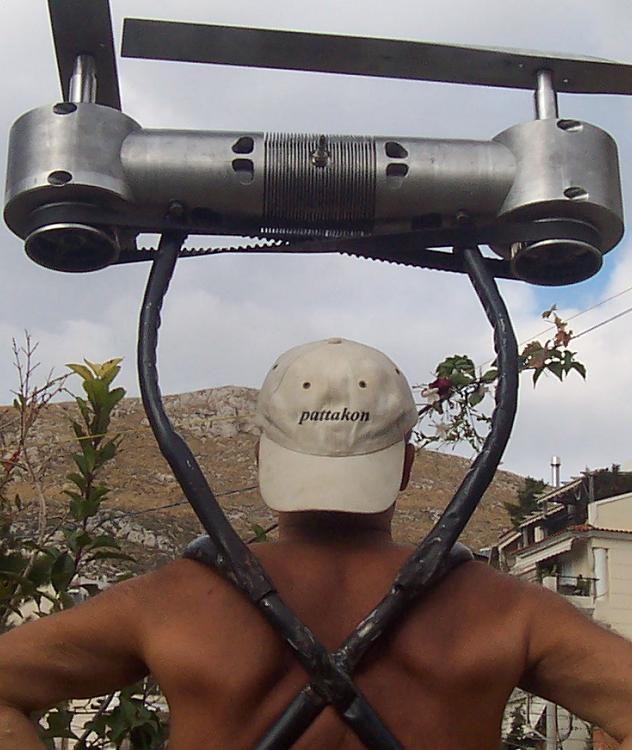
While nothing is optimized (for power and thrust measurements), it demonstrates several of its characteristics. For instance, it shows a perfectly vibration-free and reaction-free operation (the engine is free to move around; see the moment of the hand-cranking).
That this “propulsion unit” liberates the delicate frame of a light airplane from reaction torque and from vibrations of all kinds, is a fact and a significant advantage.
With less than 20Kg (44lb) total weight (if the unnecessary material is removed, the weight can drop a few more kilos) this 500cc direct-injection Diesel prototype (by the way: it is over-scavenged; the diameter of the scavenge side of the piston is bigger than the diameter of the combustion side of the piston) and some 30% additional time for the combustion of the “slow to get burned” diesel fuel (which means it can provide its peak power at around 6,000 rpm while all diesels have their peak power at or below 4,500 rpm) this engine can replace in many applications the conventional spark and compression ignition engines.
With the PatATi Opposed Piston Portable Flyer things get simpler.
For instance, no reed valves are required (the connecting rod in cooperation with the piston and the cylinder offer both, asymmetric intake and asymmetric transfer).
For instance, conventional propellers replace the wide-Vee unconventional propellers of the OPRE Portable Flyer.
The PatATi OP prototype is close to complete.
And there is no better dyno-test than putting a pair of propellers on the counter-rotating crankshafts and lifting a man a few centimeters above the ground.
When?
Soon I hope.
Hello Roger Graham.
I think your questions have been answered in previous posts.
The link of Greg Locock (Continental toothed belts) shows that the twisting - into limits – of a tooth belt is according the specifications of the manufacturers.
The successful use of a twisted tooth belt in the GP500 championship 50 years ago.
The use of tooth belts at the final transmission of motorcycles like the BMW 800F.
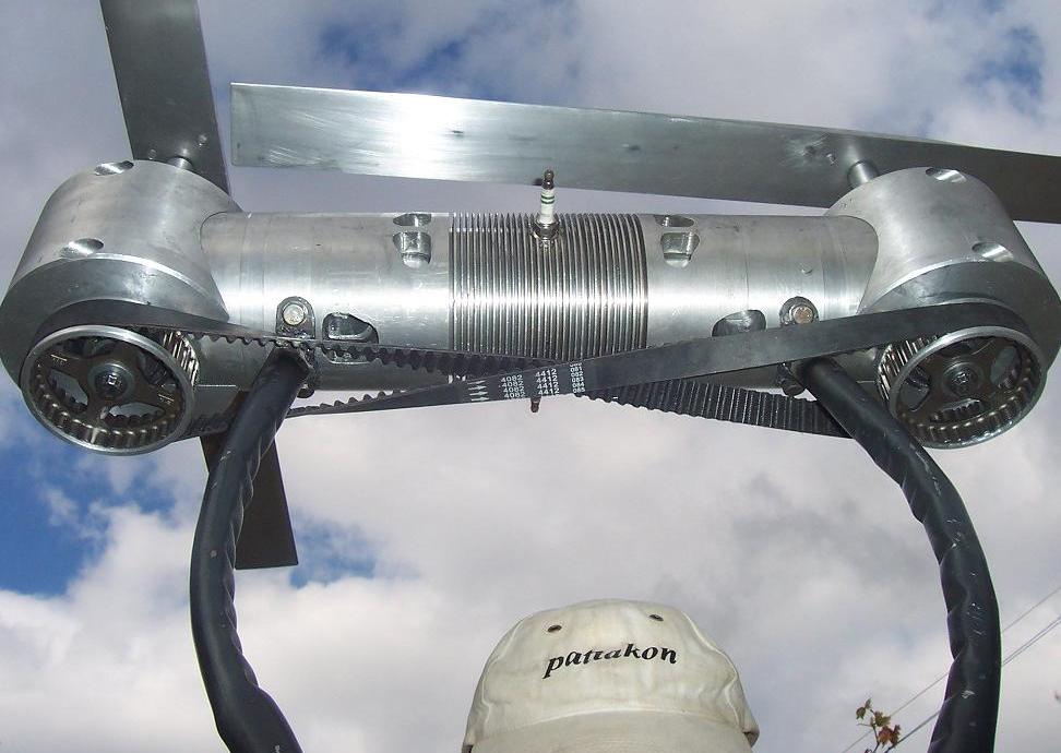
What is the difference of the PatBelt?
It synchronizes two counter-rotating shafts in a simple, lightweight and efficient way. No need for cases, or for bearings, or for lubrication.
And it can be used in other applications, too.
For instance, for driving the counter-rotating balance shaft of the cross-plane four-in-line, allowing its mounting anywhere.
Hello Imaginesix
As Wuzak explained, "the simplest, most reliable and lightest solution provided by Greg Locock", that one you like the most, is not functional.
As for the PatBelt, the solution of a long existing problem in an unconventional ans simple way is, at least, interesting.
If the PatBelt proves OK in the Portable Flyer, there are several other applications to be used.
Instead of keeping the attention towards the mass production of a prototype you are making, you can alternatively keep your attention towards the future.
Hello Wuzak and Lee Nicolle:
We know the advantages of bridging the crankshafts by gears (the OPRE prototype engines built so far use this method of synchronization), we also know their disadvantages (weight, cost, lash, bearings, casing, mounting, noise etc).
If the PatBelt operates as we expect, it is a better solution for this specific application, at least.
Hello MatsNorway
Putting a few "half a meter long" rods (actually: conecting rods), and some additional crankpins on the crankshafts, and a casing, seems more complicated and expensive than building the complete PatATi Opposed Piston engine.
Think about it.
Make a drawing of your solution and compare it to the PatBelt Twisted tooth belt.
Hello Allan Lupton
Bevel gears and rotating shaft seems as the best alternative if no toothed belts are allowed.
Hello Fykcha:
You write:
"Sorry to take things off topic, but I had a quick thought. Is there a mechanism to allow the pilot to rotate around the vertical axis like a conventional rotary wing aircraft?"
With the PatATi Portable Flyer hovering, a lot of high speed air is flowing around the pilot / rider. The legs and hands of the rider / pilot can be used to change this flow and to control, this way, the yaw (i.e. the rotation about the perpendicular axis).
If it is not clear, let me know to further explain.
Thanks
Manolis Pattakos


