You write:
"Manolis- Quit acting like a lawyer.
It is impossible for a belt span that has close to zero structural buckling capability to transmit force in compression. In reality, in order for what you claim to happen to occur would require the preload tension in the belt to exceed any cyclic force variations produced during operation. In your case this would mean the preload in the belt span would need to be more than 100% of the max tension force the belt span experiences during operation. It also means that one span of the belt will be subjected to at least 200% of the max operating loads.
This is only possible if the belt operating loads are fairly modest."
You are right in that "a belt never transmits force in compression".
The capacity of the tooth belt of the PatATi Opposed Piston engine must exceed the resulting torque difference at the two crankshaft.
But note that the PatATi OP engine has a common combustion chamber giving the same instant pressure on the two piston crowns and that the zero phase difference between the two crankshafts gives the same eccentricity (normal distance of the center of the crankshaft from the line connecting the small end center with the big end center of its connecting rod) at the two sides of the engine.
The torque on each crankshaft is the product of the above "instant pressure", of the above "eccentricity", of the piston area and of the "1/cos(f)", wherein f is the leaning angle of the connecting rod from the the cylinder axis.
You need a substantial difference between the two eccentricities (i.e. a substantial phase difference between the two crankshafts) in order to have some significant torque difference to load the timing belt.
The timing belt needs to be capable to take this torque difference.
So, the PatBelt of the PatATi Opposed Piston is not dealing with the torque of, or with the power provided by, the engine, but only with the torque difference provided to the two crankshafts. As long as the belt keeps the two crankshafts in phase (or near in phase) the torque difference is several times (say a few dozens) smaller.
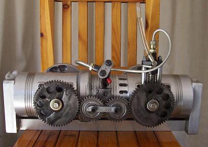
Compare the case with the loading of the tooth belt of the BMW F800S/ST wherein the complete amount of the torque (and power) is transmitted through the loaded span of the belt.
Thanks
Manolis Pattakos
Edited by manolis, 18 November 2014 - 07:03.