Jump to content


Photo
- - - - -

PatTra: Extending the Transmission Gear Ratio Range of CVTs


  • Please log in to reply
9 replies to this topic

#1 manolis

manolis
  • Member

  • 935 posts
  • Joined: May 03

Posted 15 March 2016 - 05:21

Hello all.

In a belt CVT for a car, scooter, ATV etc, an even lower gear ratio at low-gear improves the acceleration, and an even higher gear ratio at high-gear improves the mileage and reduces the noise. This is why the Transmission Gear Ratio Range (TGRR), defined as the ratio of the higher gear ratio to the lower gear ratio, is so important.

The new generation of steel belt CVTs for cars expands the Transmission Gear Ratio Range from the previous 6.0 to the current global top level of 7.0

PatTra11.gif

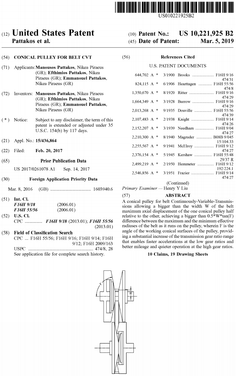
The allowed axial displacement Lmax of the one conical-pulley-half relative to the other conical-pulley-half is limited by the effective width W of the belt. If an axial displacement L wider than W is applied to the one conical-pulley-half towards the other conical-pulley-half, it will cause collision of the working conical surfaces of the conical pulley.

The need for a higher "Transmission Gear Ratio Range" is more crucial in trucks, in agricultural tractors, in machinery equipment etc.

In the following image the PatTra mechanism (shown at "slow motion" at right):

PatTra3_fast.gif

allows the belt to run at bigger diameters, enabling a larger Transmission Gear Ratio Range.

A single-step PatTra (as in the animation above), using the same belt profile and the same minimum actual-diameter in the conical pulleys, doubles the "Transmission Gear Ratio Range".

A two-step PatTra:

PatTra4.gif

enables a four times larger TGRR (the TGRR=7.0, which is the current world top, goes to TGRR=28.0).


Given the angle F of the conical pulleys, given the working width W of the belt, and given the minimum effective radius Ri wherein the belt is allowed to run on the pulley, the transmission gear ratio range (TGRR) is defined (and limited).

The effective radius R wherein the belt runs is calculated as:

R=Ri+0.5*L*tan(F),

wherein L is the axial displacement (i.e. the displacement along the rotation axis of the conical pulley shaft) of the one conical-pulley-half relative to the other (with L=0 when the belt runs at the minimum effective radius Ri).

The tan(F) is the tangent of the angle F.

For specific Ri and F, the R gets maximized when the L is maximized, so the maximum possible effective radius Ro at which the belt can run on the conical pulley is:

Ro=Ri+0.5*Lmax*tan(F).

The maximum allowed radial displacement Ro-Ri of the belt as it cooperates with the conical pulley is:

MaximumAllowedRadialDisplacement=Ro-Ri=0.5*Lmax*tan(F).

The maximum pulley ratio Ro/Ri is:

MaximumPulleyRatio=Ro/Ri=1+(0.5*Lmax*tan(F)/Ri)

And supposing similar drive and driven pulleys (which enables the maximum TGRR), the attainable Transmission Gear Ratio Range becomes:

TGRR=MaximumPulleyRatio^2=(1+(0.5*Lmax*tan(F)/Ri))^2

As explained previously, the Lmax cannot be bigger than W (W is the effective width of the belt), limiting the Transmission Gear Ratio Range to:

TGRR=(1+(0.5*W*tan(F)/Ri))^2

limiting also the maximum allowed radial displacement RD of the belt to:

MaximumAllowedRadialDisplacement=Ro-Ri=0.5*W*tan(F).


For instance, with a minimum radius Ri=50mm, a conical pulley angle F=79degrees (i.e. 90degrees-F=11degrees) and a belt width W=32mm:

Ro=132.3

MaximumPulleyRatio=2.65

MaximumAllowedRadialDisplacement=82.3mm

TGRR=2.65^2=7.0


PatTra13.gif

Hydraulic control.
In the image above, the belt runs on the inner conical surface S1 of the left pulley half.
In the image below, the belt runs on the outer conical surface S2 (the inner section of the left pulley half, that with the conical surface S1 on it, is displaced to the left by the right half of the pulley).

PatTra14.gif

In the following image the control is mechanical (a variator in the drive pulley, at top, a spring with an actuation linkage in the driven pulley, at bottom) :

PatTra15.gif


A different, and simple, approach, preferable for some applications, is the "comb" conical pulley wherein the two pulleys can get closer to each other without collision:

PatTra_Comb_1.gif

PatTra_Comb_2.gif


Another different, and simple, approach, preferable for some applications, is the "radial comb" conical pulley wherein the two pulleys can approach each other without collision (stereoscopic image):

PatTra_Radial_Comb_STE.jpg

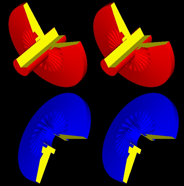
The grooves on the one conical pulley half allow the conical surface of the other pulley half to enter without collision, and vice versa.
This type fits with continues belts (like the elastic belts used in the scooters).


Thoughts?

Objections?

Thanks
Manolis Pattakos

Advertisement

#2 blkirk

blkirk
  • Member

  • 319 posts
  • Joined: March 00

Posted 15 March 2016 - 13:41

I like your first idea with the collapsing/telescoping pulley center.  The radial comb idea is more elegant, but I would be afraid that the comb teeth would chew up the edges of the belt.  Also, any little bits of dust and debris could get lodged in the comb and keep the pulley from collapsing fully.


#3 MatsNorway

MatsNorway
  • Member

  • 2,822 posts
  • Joined: December 09

Posted 15 March 2016 - 16:20

See if you can make the inner part collapse where the comb is now. If the belt is not there it does not matter anyway.


#4 Kelpiecross

Kelpiecross
  • Member

  • 1,730 posts
  • Joined: October 10

Posted 16 March 2016 - 04:31


I like the ideas too - but maybe the "comb" version would get blocked with bits of rubber etc.?

#5 manolis

manolis
  • Member

  • 935 posts
  • Joined: May 03

Posted 16 March 2016 - 04:53

Hello

The edges of the teeth of the radial comb version can be rounded to avoid the "chew up of the edges of the belt".

In practice, the way the belt runs between the two complimentary "radial combs" may improve things: for the same torque, less clamping of the belt between the two pulley halves is required.

The optimization of the shape of the grooves is an interesting problem.
Is it better a single but wider groove at the big eccentricities, or it is better to divide the wide groove into a pair of thinner grooves?


By the way, the grooves can be made a little deeper to make room for any "little bits of dust and debris lodged in the comb", allowing the pulleys to collapse fully for a long time.

Thanks
Manolis Pattakos

Edited by manolis, 16 March 2016 - 04:58.


#6 bigleagueslider

bigleagueslider
  • Member

  • 1,235 posts
  • Joined: March 11

Posted 20 March 2016 - 03:04

As noted there are already production link-chain type CVTs that provide a drive ratio close to 7.0, which is quite adequate for automotive applications. A rubber V-belt CVT would not be durable enough for any automotive use. If a greater drive ratio is required from an automotive CVT, there are approaches like geared neutral that can be used.


#7 bigleagueslider

bigleagueslider
  • Member

  • 1,235 posts
  • Joined: March 11

Posted 20 March 2016 - 03:04

As noted there are already production link-chain type CVTs that provide a drive ratio close to 7.0, which is quite adequate for automotive applications. A rubber V-belt CVT would not be durable enough for any automotive use. If a greater drive ratio is required from an automotive CVT, there are approaches like geared neutral that can be used.


#8 manolis

manolis
  • Member

  • 935 posts
  • Joined: May 03

Posted 20 March 2016 - 07:29

Hello BigLeagueSlider

The PatTra CVT fits with “link-chain” V-belts (metal belts) and with rubber V-belts.
There are millions of scooters on the roads using rubber V-belts in their CVT’s.

You can add a “gearbox” to increase the “total” TGRR of a car CVT. Nissan uses a planetary one.
But again, with a basic CVT (comprising the two conical pulleys and the V-belt) having a bigger Transmission Gear Ratio Range, things further improve either with, or without, a gearbox.

A truck or an agricultural tractor with a bigger (and bigger) TGRR has more capabilities, and the PatTra can offer a much bigger TGRR.

Nissan and Toyota fight for years for a small increase (from 6 to 7) of the TGRR. The PatTra (with one step) over-doubles the TGRR and is easy in control and implementation (think how it effects the size / capacity of the torque converter).


Even in a bicycle like:

PatBox_CVT_bicycle_1.gif

if you want to avoid a “reduction gearing” (like those in the rear wheels of the scooters), the PatTra (applied, in the simplest case, only in the rear (the smaller) pulley) provides a simple and functional solution (I mean the PatTra with the radial-comb design).


Thanks
Manolis Pattakos

#9 manolis

manolis
  • Member

  • 935 posts
  • Joined: May 03

Posted 14 February 2019 - 04:44

Hello all.


The CVT automatic transmission is coming in fashion.


The US patent 10,221,925 is to be issued for the PatTra CVT on March 5, 2019.


Here is a PatTra version providing a TGRR (transmission gear ratio range) over 28 (the current world top is 7):


PatTra_both_halves.gif


Thanks

Manolis Pattakos


#10 manolis

manolis
  • Member

  • 935 posts
  • Joined: May 03

Posted 05 March 2019 - 16:47

Hello all.
 
Today it is published the US10,221,925 patent for the PatTra CVT (Continuously Variable Transmission):
 
US_10221925_PatTra_patent.png
 
The complete patent document is at http://www.pattakon....1925_PatTra.pdf
 
 
Thanks
Manolis Pattakos