Jump to content


Photo
- - - - -

PatRon Harmonically Reciprocating Piston Rotary Engine


  • Please log in to reply
26 replies to this topic

#1 manolis

manolis
  • Member

  • 935 posts
  • Joined: May 03

Posted 28 February 2017 - 08:13

Hello all.

Here :

PatRon2.gif

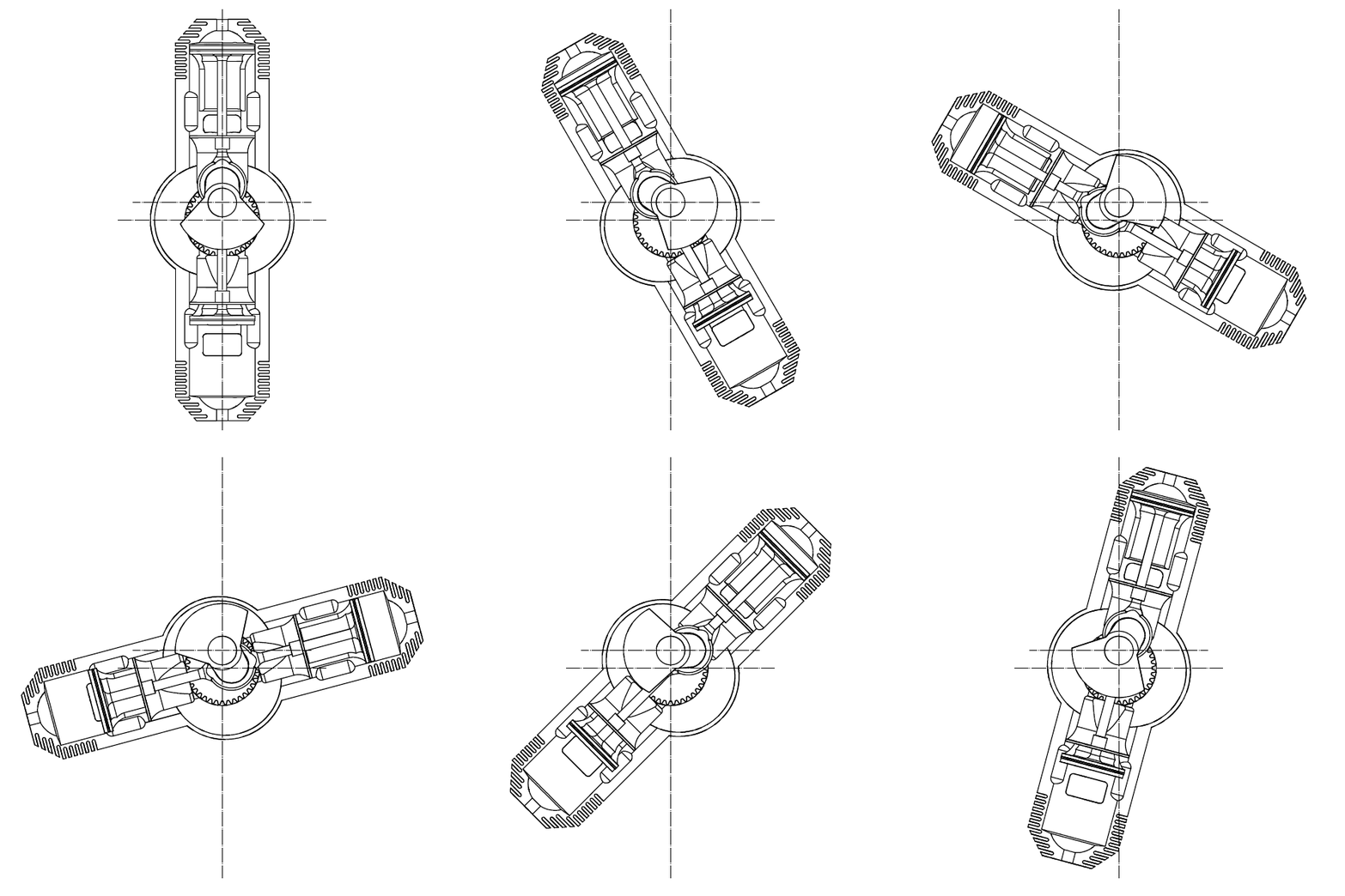
is a PatRon Reciprocating-Piston Rotary-Engine.

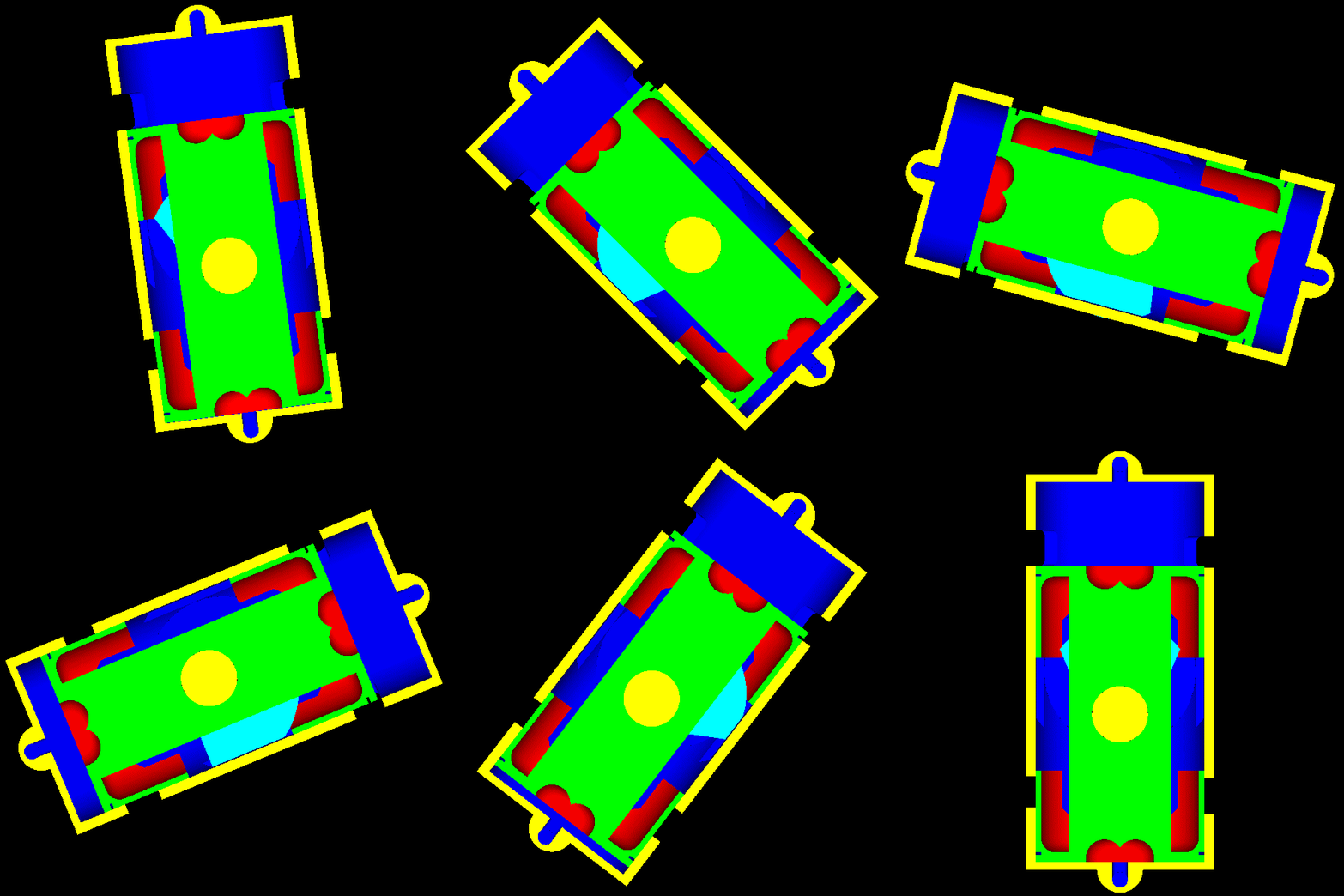
PatRon1.gif

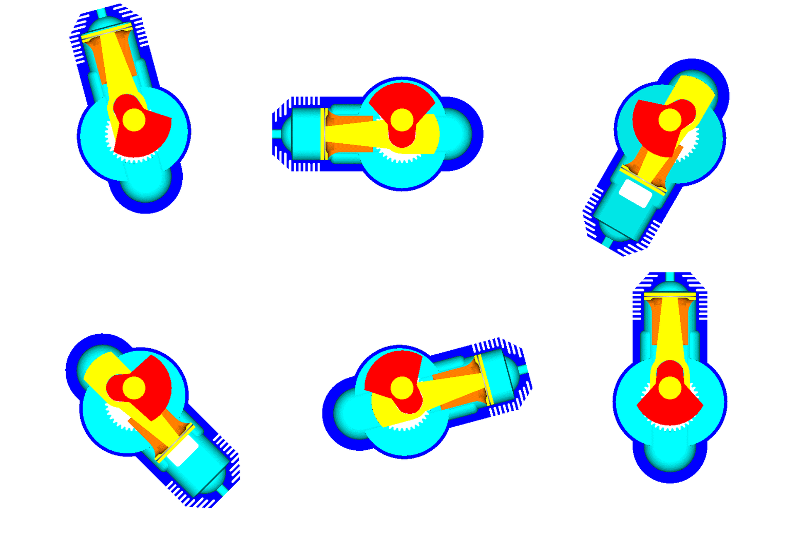
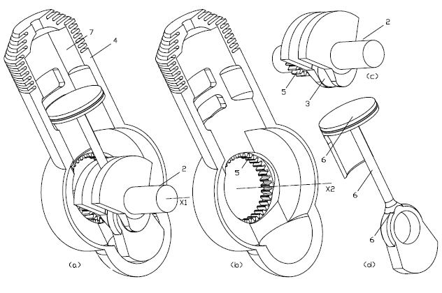
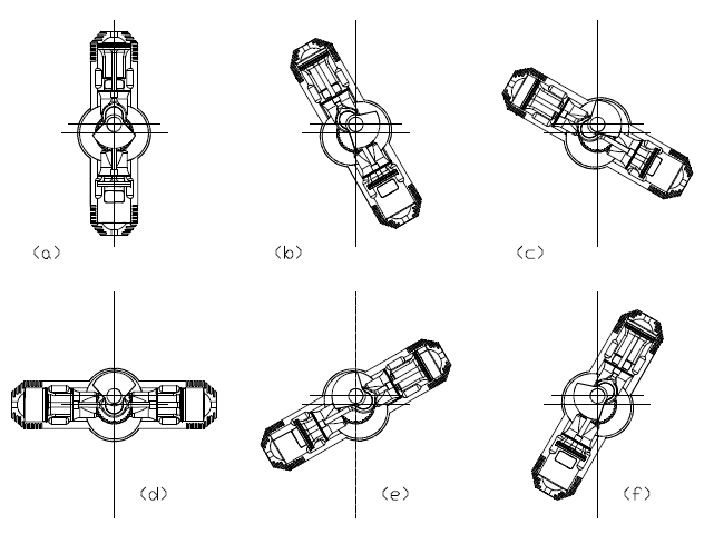
It comprises a crankshaft, a piston rotatably supported on a crankpin of the crankshaft, and a rotating cylinder wherein the piston reciprocates sealing one side of a combustion chamber.

For a complete reciprocation of the piston inside the cylinder they are required two rotations of the crankshaft.

Without external balance shafts, the balancing of the inertia force, moment and torque is perfect (even for the single cylinder).

PatRon11.gif

A synchronizing gearing keeps the cylinder rotating at the same direction with the crankshaft and at half angular speed than the crankshaft; the high pressure gas in the combustion chamber does not load the synchronizing gearing.

Not only the power passes directly to the load and the synchronizing gearing remains unloaded but, additionally, the cylinder liner remains rid of thrust loads. Think how.


The stroke S of the piston along the cylinder equals to four times the distance between the (fixed) rotation axis of the crankshaft and the (fixed) rotation axis of the cylinder.

The relation between the displacement D of the piston along its cylinder and the rotation angle f of the crankshaft is like:

D=(S/2)*sin(f/2)

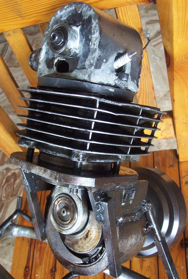
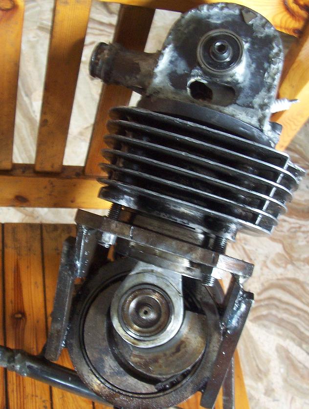
which is a pure sinusoidal (or harmonic) motion.

PatRon4.gif


With the PatRon:

* the power passes directly to the load (more directly than in the conventional reciprocating piston engines: there is no connecting rod (the piston is rotatably mounted directly on the crankpin), there are no thrust loads on the cylinder liner),

* the synchronizing gearing remains unloaded by the high gas pressures during the compression - combustion – expansion,

* the two halves of the "immovable" casing (one per side of the spinning cylinder) are easily coupled / bridged forming a space wherein the cylinder spins safely,

PatRon10.gif

* only one crankshaft is required (and only a set of balance webs secured on the crankshaft for the complete balancing of the engine),

* there are no high speed bearings loaded by heavy inertia loads,

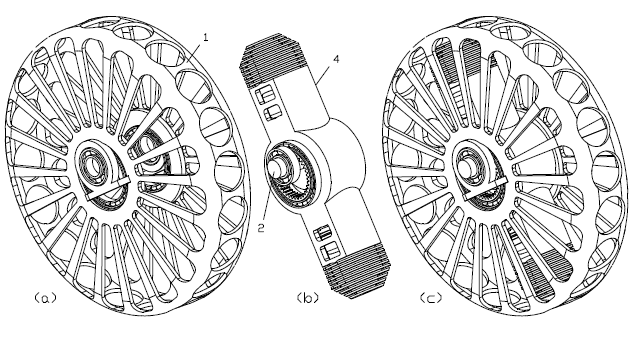
* in case of air-cooling the rotation of the cylinder simplifies things (the cylinder is also the fan),

* if desired, the power can be delivered by the rotating cylinder (which spins at half crankshaft speed),

* it is for single acting, for double acting pistons, even for “multi-acting” single-piece pistons,

* it is for two-stroke and four-stroke engines, etc


For more: http://www.pattakon....takonPatRon.htm


In a few words:

The PatRon brings the good sealing and the small surface to volume ratio of the reciprocating piston engines in the rotary engines, without introducing significant side effects.


Thoughts?

Objections?

Thanks
Manolis Pattakos

Advertisement

#2 MatsNorway

MatsNorway
  • Member

  • 2,822 posts
  • Joined: December 09

Posted 28 February 2017 - 11:38

This one is cool. Because it is simple. But surely the gears needs to be quite beefy?


#3 munks

munks
  • Member

  • 428 posts
  • Joined: January 03

Posted 28 February 2017 - 15:16

It goes without saying that this never occurred to me.


#4 manolis

manolis
  • Member

  • 935 posts
  • Joined: May 03

Posted 28 February 2017 - 16:52

Hello MatsNorway.

In the PatRon rotary the gears can be quite skinny because they are not loaded by the high pressure in the combustion chamber.

Only during a fast deceleration with the engine (engine brake) the gears of the PatRon are heavily loaded (in a way similar to the Wankel rotary engine, with the difference that the momentum of inertia of the rotor of a Wankel is several times larger than the momentum of inertia of a "double acting" piston of a PatRon of similar capacity).


In comparison to the absence of loads on the teeth of the gears in a PatRon rotary engine,
the (synchronizing) gears of the LiquidPiston (which is supported by the MIT, the DARPA, the Shikorsky) "reverse-Wankel" rotary engine are heavily loaded by the high pressure in the combustion chamber (worse even: the necessarily extra-oversquare design of the LiquidPiston and the change of the direction of the loads on the teeth of the gears at the TDC).

Any backlash / slapping of the teeth of the synchronizing gears of the LiquidPiston rotary engine will cause, in the long term, reliability issues. Besides, heavily loaded gears also mean friction loss.

Thanks
Manolis Pattakos

#5 Kelpiecross

Kelpiecross
  • Member

  • 1,730 posts
  • Joined: October 10

Posted 03 March 2017 - 05:10


Manny - rotating engines (where the whole thing turns) usually have problems with the attachment of intake and exhaust system (and water cooling if required) - how does yours work?

#6 manolis

manolis
  • Member

  • 935 posts
  • Joined: May 03

Posted 05 March 2017 - 04:38

Hello Kelpiecross.

You write:
“Manny - rotating engines (where the whole thing turns) usually have problems with the attachment of intake and exhaust system (and water cooling if required) - how does yours work?”

The attachment of the intake and exhaust is no more complicated than the attachment of the intake and exhaust in the Cross / Cross-Bishop and / Cross-Watson rotary valve engines.

For a rotary engine the air-cooling fits better: the fins of the cylinder move in the ambient air even during idling (vehicle stopped).


I cannot deny that the added complication is an issue.

However there are some advantages in the PatRon design that counterbalance the complication of attaching to the stationary casing the rotating intake and exhaust.


One of these advantages over the conventional reciprocating engine is the reduced friction which means increased brake thermal efficiency.

If you look carefully at this animation:

PatRon15Slow.gif

the geometry of the PatRon rotary engine manages to keep the crankpin on the axis along the cylinder, i.e. directly under the force applied by the high pressure gas onto the piston head.

What this means?

There are no thrust loads between the cylinder and the piston skirt, a main cause of mechanical friction in the conventional reciprocating piston engines. Without loads to take, a piston skirt is useless in a 4-stroke PatRon.

This built-in characteristic of the PatRon design saves mechanical energy and increases the BTE because, despite the PatRon is a rotary engine, it has as efficient sealing and as compact combustion chamber and as small surface-to-volume ratio as the conventional reciprocating piston engines.


Significant for the efficiency, the noise and the “long term” reliability is that the teeth of the synchronizing gearing of the PatRon are not loaded by the gas pressure force.

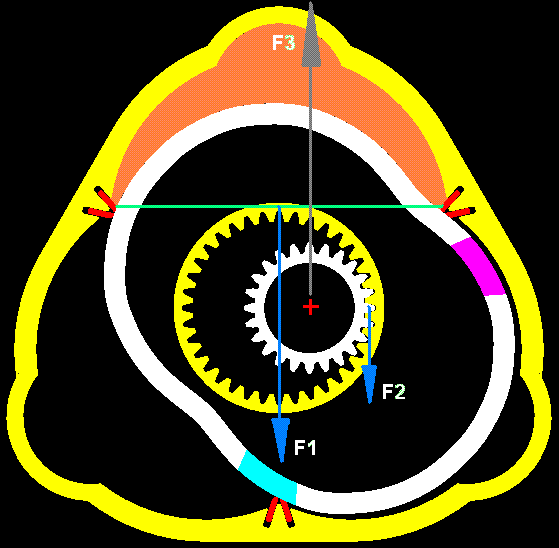
For comparison, this drawing shows some loads in a reverse-Wankel rotary engine of LiquidPiston (supported by the MIT, the DARPA (3.5 million dollars sofar) and the Shikorsky)

LiquidPiston_Forces.gif

The top working chamber (orange color) is at expansion.

The total force onto the part of the rotor which seals the lower side of the top working chamber is F1 (it equals to the length of the green horizontal line times the depth of the chamber (the dimension of the chamber normal to the drawing plane) times the gas pressure).

This force is eccentric relative to the rotation axis (at the red cross) of the rotor.
The other one who can apply a force to the rotor is the ring gear. The Force F2 the ring gear applies to the rotor is, in the worst case (eccentric pin at 90 degrees after the TDC) half than F1, so the total force required by the bearing whereon the rotor is rotatably mounted is F3=F1+F2 (and varies from F1 to 1.5*F1 depending on the eccentric pin angle)

Due to the extra-over-square design of the LiquidPiston, the F1 is already too heavy.

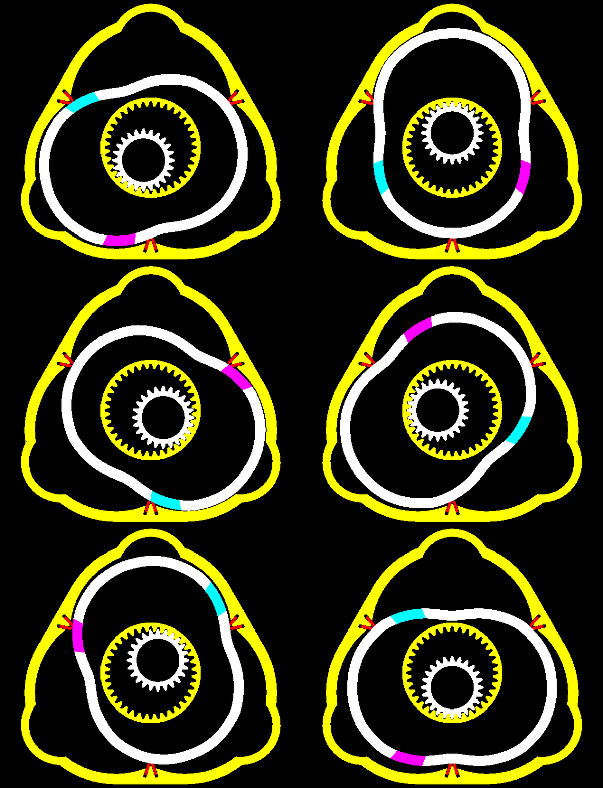
The 50% higher revs of the heavily loaded orbiting bearing of the rotor

PatWankel_iGR_5.gif

worsens even more the situation.

Worse than the increased friction is the impact heavy loads on the teeth of the synchronizing gearing (these load have different direction before and after the TDC). Any wear on the teeth increases the backlash and accelerates the wear.


Another significant advantage of the PatRon is the perfect balancing even in with a single working chamber.

Imagine a single cylinder 50cc 2-stroke PatRon with single sided piston in a chainsaw or in another agricultural equipment or in a portable electric generator set : without balance webs others than those on the crankshaft, it has an inertial vibration free quality as perfect as a Wankel, or as perfect as the best V12 conventional engines.


When a new design arrives, the real question is whether the added complication (like the attachment of the intake and exhaust “issue”) justifies the advantages the new design brings.

Thanks
Manolis Pattakos

#7 Kelpiecross

Kelpiecross
  • Member

  • 1,730 posts
  • Joined: October 10

Posted 06 March 2017 - 23:50


Manny - can you arrange some sort of "stop" function on your animated drawings? Might be easier to understand then.

Is your two cylinder engine a "true" rotary - or do the pistons still undergo varying acceleration? Or a constant acceleration due to the spinning motion?

Your two cylinder engine could be possibly more simply arranged if it was made in the sense of a WW1 aero engine rotary - where the pistons don't suffer a varying acceleration.

#8 manolis

manolis
  • Member

  • 935 posts
  • Joined: May 03

Posted 07 March 2017 - 05:13

Hello Kelpiecross.

You write:
“Manny - can you arrange some sort of "stop" function on your animated drawings? Might be easier to understand then.”

There is a slow motion version of the animation at http://www.pattakon....atRon15Slow.gif .

If you want to see each slide separately, you need the GIF-Animator of Microsoft (free in the Internet; it is for windows).


You also write:
"Is your two cylinder engine a "true" rotary - or do the pistons still undergo varying acceleration? Or a constant acceleration due to the spinning motion?
Your two cylinder engine could be possibly more simply arranged if it was made in the sense of a WW1 aero engine rotary - where the pistons don't suffer a varying acceleration."

The centre of the double acting piston is in the center of the crankpin and orbits at constant angular velocity together with the crankpin.
The piston as a body performs another motion: it spins about the center of the crankpin at constant angular velocity (which is half than the angular velocity of the crankshaft).
As happens in the Wankel rotary engine, the orbiting combined with the spinning (both at constant angular velocities) the overall energy of the piston is constant.
In total the free inertia force is zero, the free inertia monet is zero and the free inertia torque is zero.

This is a way better balancing than in the arrangements of the Gnome and Rhone (and similar) rotary engines (and in the Radial engines) which, among others, suffer from heavy thrust loads (friction) between the cylinder liner and the piston skirt.


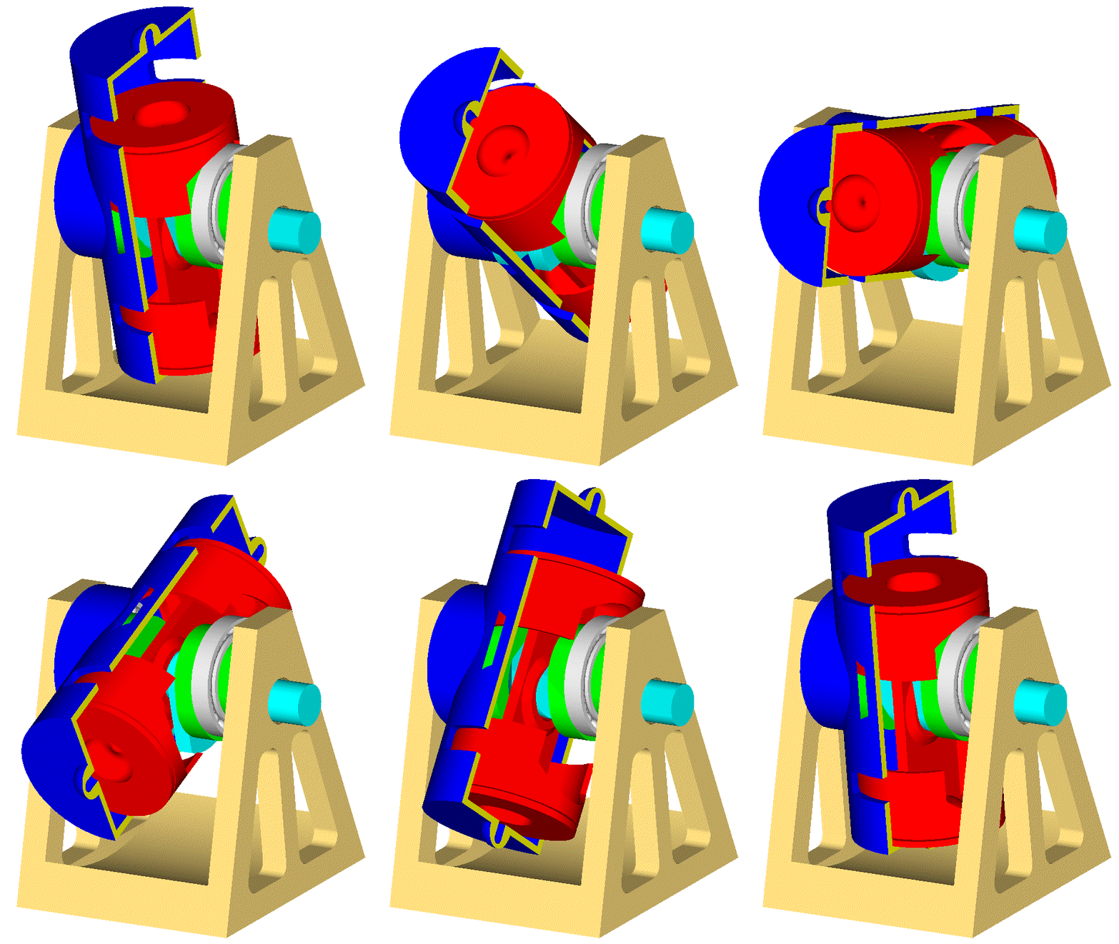
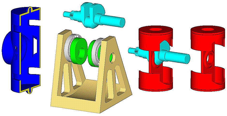
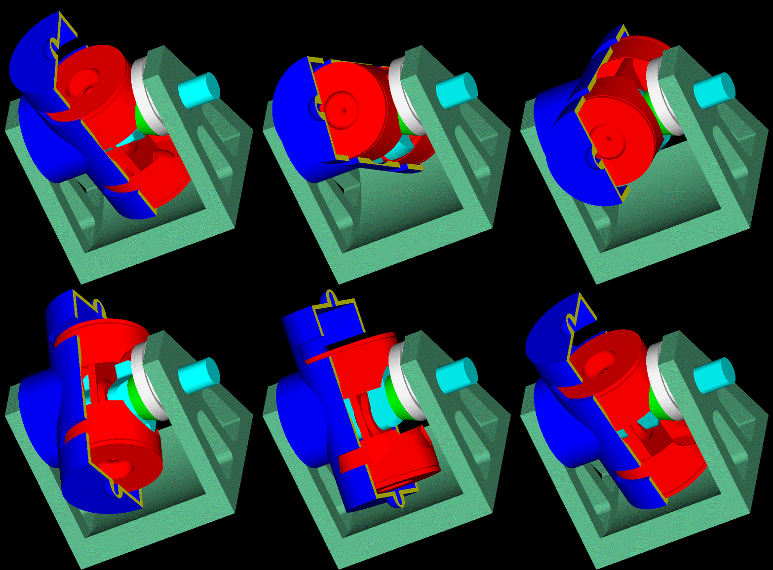
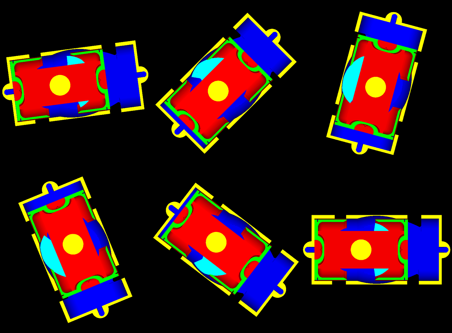
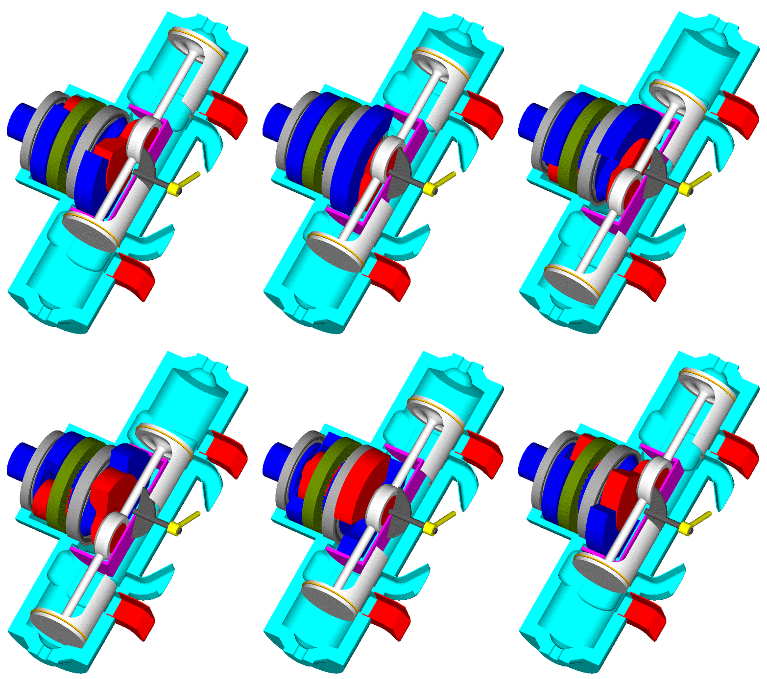
Here is a more “unconventional” PatRon for small airplanes, ultralights etc.:

PatRon_Model.gif

PatRon_Model_parts.gif


It is an over-square direct injection Diesel with plenty of piston skirts.


With 120mm bore and 60mm stroke (about as over-square as the Ducati Panigale 1299) it gives a 2-Stroke capacity of 1,350cc.

The maximum dimension of the spinning cylinder is 1ft, i.e. the distance from the top of the one cylinder head to the top of the other cylinder head is only 305mm.


The scavenging is quite strange:

At some angle of the cylinder the piston opens the “leading” port and the pressure of the gas in the cylinder drops sharply.
Several (like 10 or 15) degrees later the piston opens the trailing port, too. The exhaust happens through both ports. Gradually the leading port becomes the intake port with the trailing port being the exhaust port:
The motion of the cylinder in the ambient air pushes air to enter from the leading port to scavenge the cylinder and then to exit from the trailing port.
After the BDC the pistons moves “upwards”; initially it closes the trailing port; the air entering the cylinder from the leading port continues to enter (due to inertia) until the piston closes the leading port, too.
The gas in the cylinder is compressed. Near the TDC diesel fuel is injected into the bowl at the center of the crown of the piston.
After the TDC it follows the expansion.
After the middle stroke the piston opens the leading port (it serves as exhaust port and as intake port) and so on.

I.e. it uses neither crankcase scavenging, nor some external scavenge pump.

If it works, it makes an extremely compact, simple and lightweight Diesel, which is also perfectly balanced, which also provides some 15% longer piston dwell at the TDC as compared to the conventional Diesels (the PatRon running at 5,000 rpm gives to the combustion as much time as a conventional Diesel running at 4,500rpm), and which eliminates the load between the piston skirts and the cylinder liner (the skirts are there only to seal the crankcase).

At 5,000rpm of the cylinder (i.e. at 10,000rpm of the crankshaft) it could make some 200bhp (i.e. as much as the Ducati Panigale 1299) because it is a 2-stroke.

As for its weight, 1/4 of the Panigale 1299 engine is reasonable.

As for its Brake Thermal Efficiency, it has all the characteristics for a top BTE.


This animation is explanatory:

PatRon_Model_2.gif

(the same animation at slow motion is at http://www.pattakon....odel_2_Slow.gif )


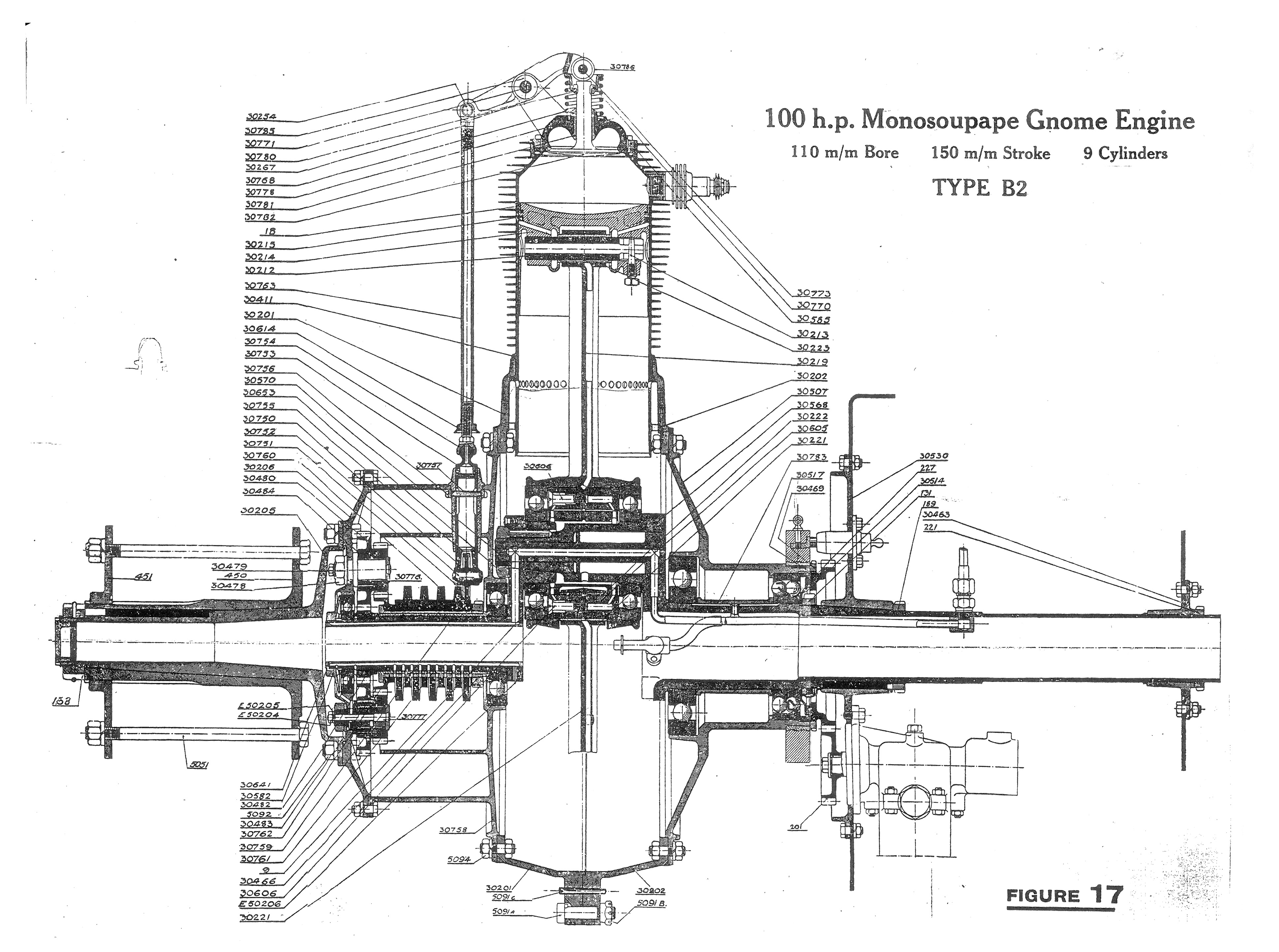
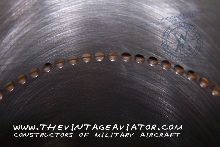
Regarding the unconventional scavenging, it resembles to the way the Gnome and Rhone rotary engines (those with the ports on the cylinder liner) were running:

Gnome_9B-2_Engine_Build%20%2828%29.jpg?i

Gnome%20B2%20Section%20from%20Instructio

(more details at http://thevintageavi...engine/historyv )

They were using the "exhaust" valve of a cylinder unconventionally: initially it was acting as an exhaust valve (during the last half of the expansion cycle and during the exhaust cycle), later (during the intake / admission cycle) it was acting as an intake valve allowing fresh "unfiltered" air to fill the cylinder; at the end of the inlet cycle rich air/fuel mixture was entering into the cylinder through the ports on the cylinder liner.

Thanks
Manolis Pattakos

Edited by manolis, 07 March 2017 - 05:21.


#9 gruntguru

gruntguru
  • Member

  • 7,642 posts
  • Joined: January 09

Posted 07 March 2017 - 06:12

A beautiful piece of machinery - especially considering it is 100 years old.


#10 manolis

manolis
  • Member

  • 935 posts
  • Joined: May 03

Posted 08 March 2017 - 05:56

Hello all.


Yesterday, in another forum a guy (CheapRacer) published this drawing :

BDC.jpg

and wrote:

“at BDC the exhaust helps drive it 'round while the open intake mouth gets self-supercharged!”


The combustion chamber is like a long room (say, a corridor) having a big window towards the north and another big window towards the south.

Outside the room there is a strong wind coming from the north (this is what the rotation of the cylinder causes).

At the end of the expansion the north window opens.
The high pressure in the room pushes a big part of the “gas” to exit from the north window and the pressure to drop sharply.

A little later the south window opens allowing gas to exit from that window too.

Due to the north wind, the flow from the north window gradually weakens, stops and reverses its direction, while the flow from the south window strengthens.

With both windows wide open (BDC), the strong north wind enters from the north window, scavenges the room (and cools down the walls, the ceiling and the floor of the room from within) and exits from the south window.

Later the south window closes, with the north window still open.

The north wind continues to enter into the room from the north window (due to inertia / ram effect) overfilling the room with air (a kind of asymmetrical port timing: the exhaust closes before the transfer).

Finally the north window of the room closes trapping the air entered, and the compression starts.


Thanks
Manolis Pattakos

Edited by manolis, 08 March 2017 - 06:06.


#11 Kelpiecross

Kelpiecross
  • Member

  • 1,730 posts
  • Joined: October 10

Posted 09 March 2017 - 04:42


Not THE Cheapy?

#12 manolis

manolis
  • Member

  • 935 posts
  • Joined: May 03

Posted 09 March 2017 - 11:01

Hello Kelpiecross.

The guy is THE CheapRacer, and the discussion is at http://www.homebuilt...ead.php?t=27167


A calculation:

For the PatRon of the animation (60mm stroke, 120mm bore, 300mm external “diameter”) the eccentricity of the ports from the center of rotation of the cylinder is about 115mm (0.115m).

At 5,000rpm of the cylinder (10,000rpm of the crankshaft) the speed of the leading port is:

0.115m * 2 * pi * 5,000 rpm / 60sec/min = 60m/sec = 215Km/h = 135mph

If this engine, mounted transversely, is powering a motorcycle, then at 185Km/h the leading port sees the air coming with 400Km/h. This could give a 10%, more or less, overcharging (RAM air).

Thanks
Manolis Pattakos

#13 manolis

manolis
  • Member

  • 935 posts
  • Joined: May 03

Posted 14 March 2017 - 03:36

Hello all.

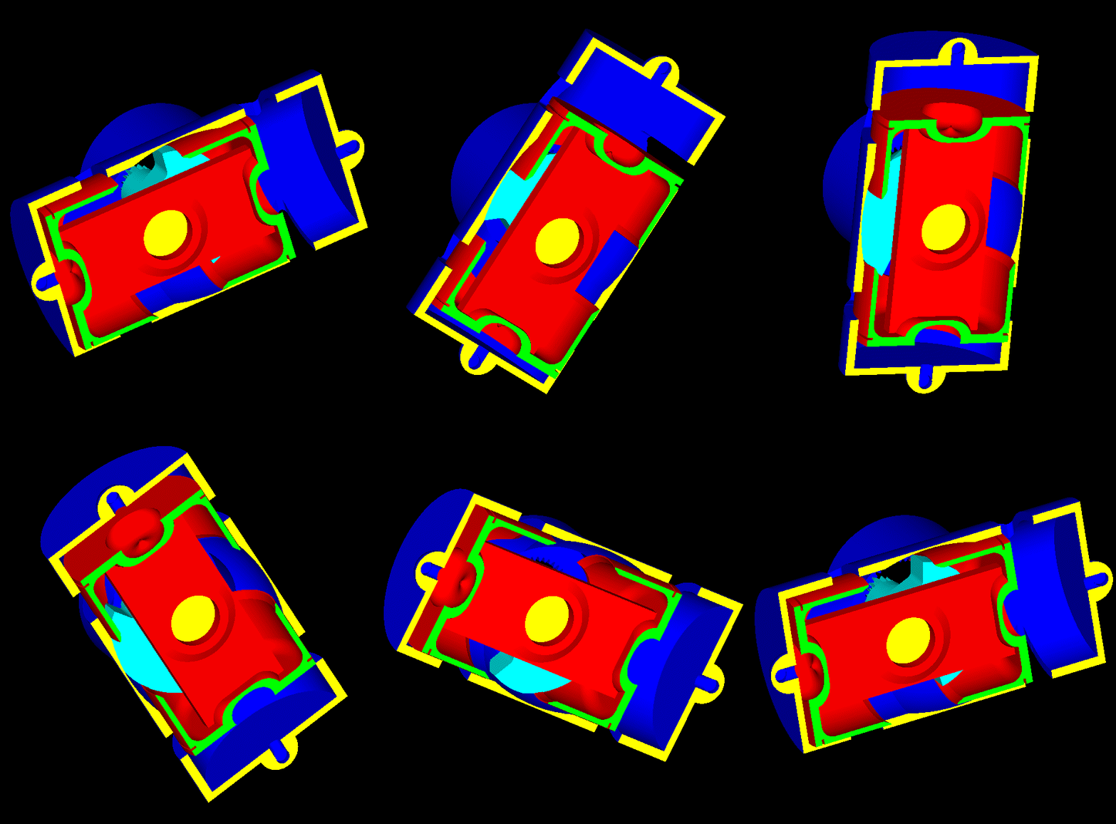
In the GIF video-animation here:

PatRon_GIF_Video_1.gif

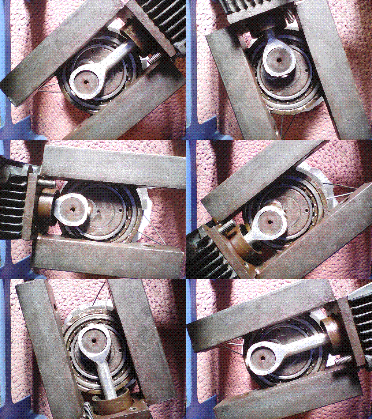
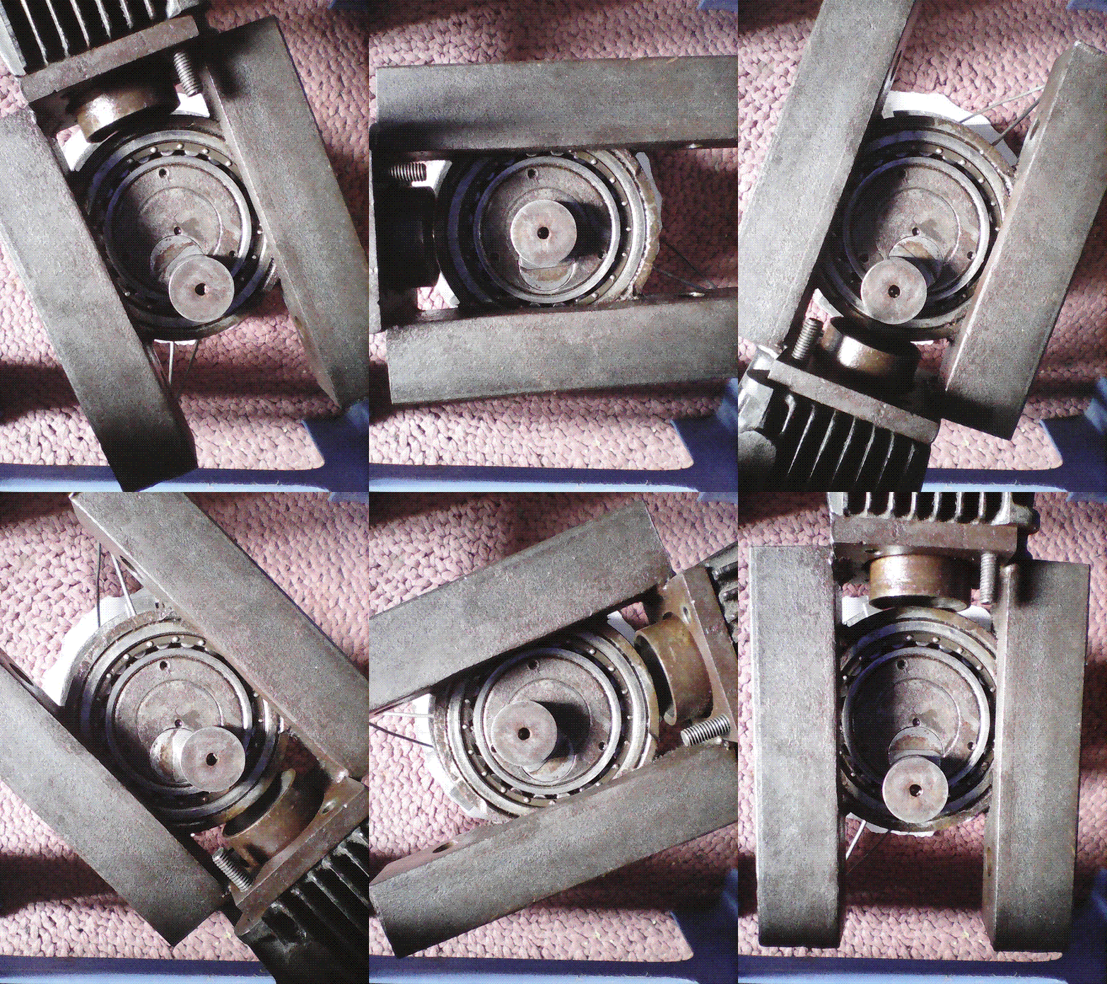
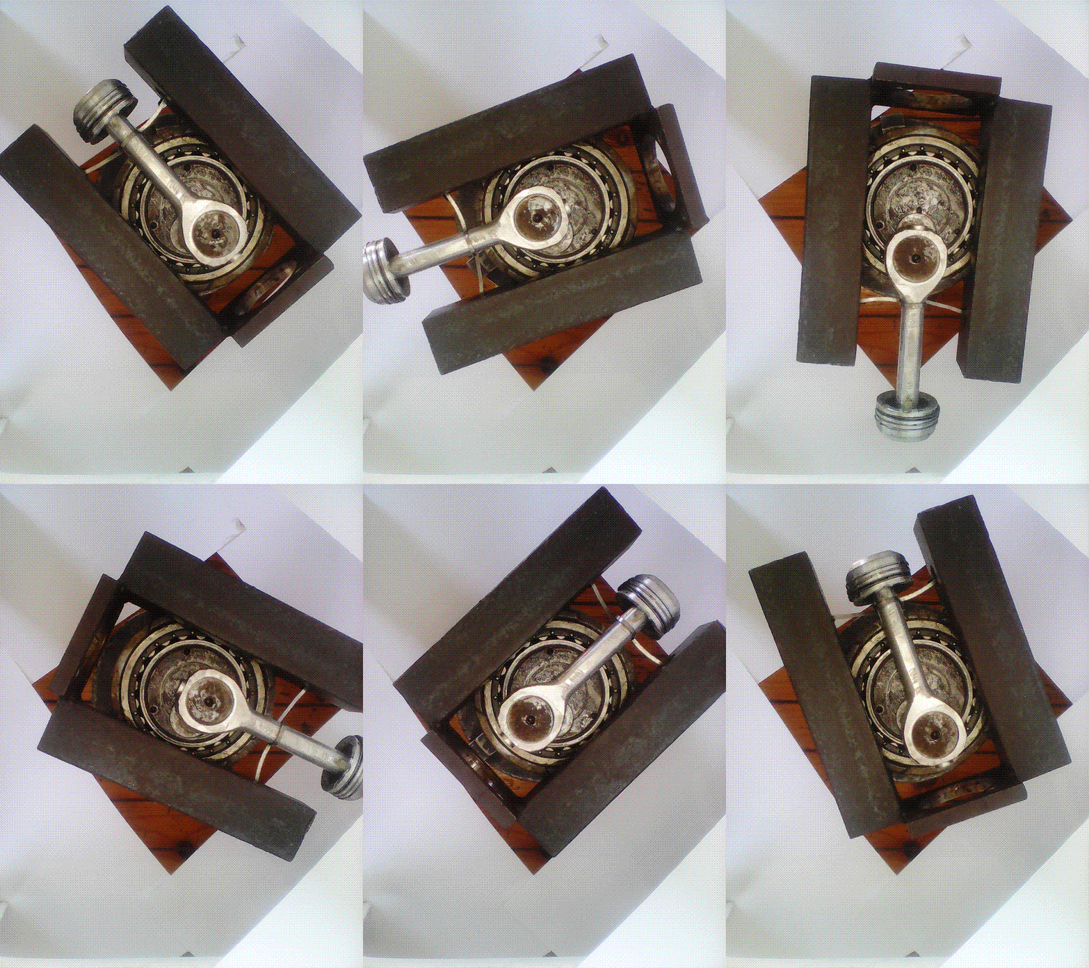
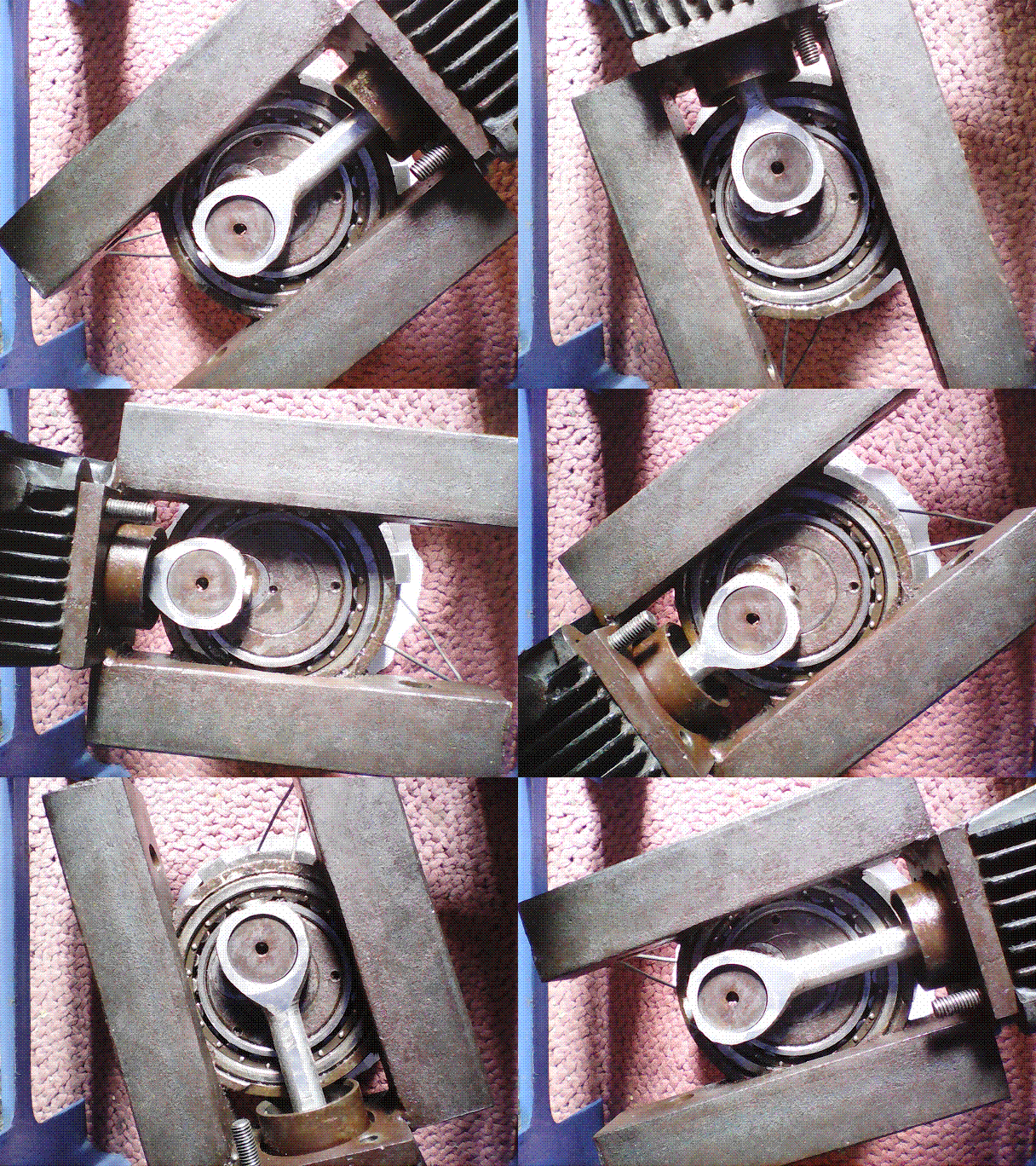
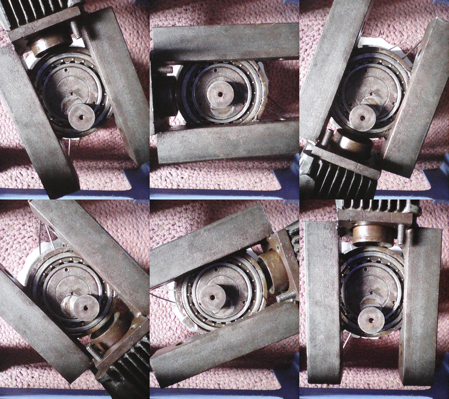
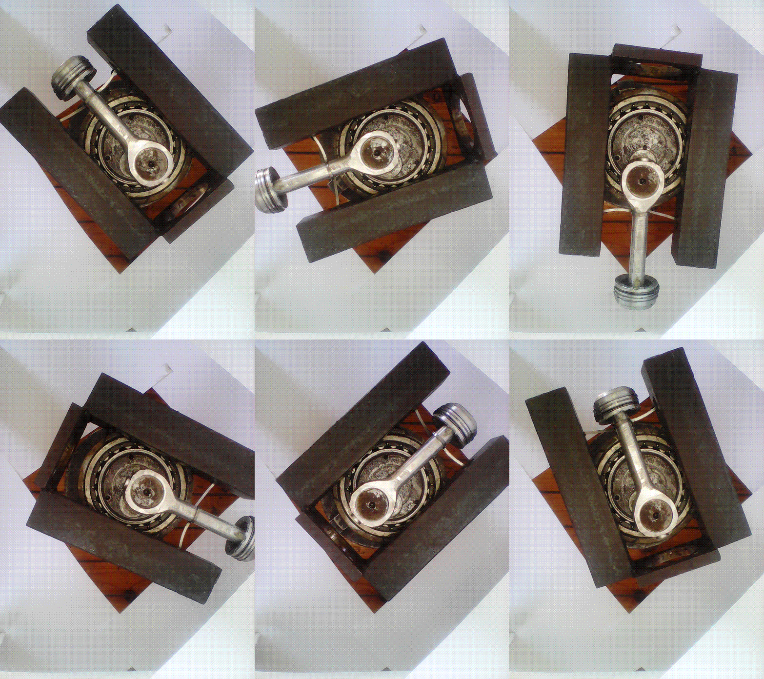
they are shown the spinning cylinder (it is from a Honda C-50), the spinning crankshaft (you can see its main journal spinning about a stationary axis, you can also see the crankpin of the crankshaft holding the piston rod that holds the piston head (which is also from a Honda C-50) that reciprocates inside the spinning cylinder.


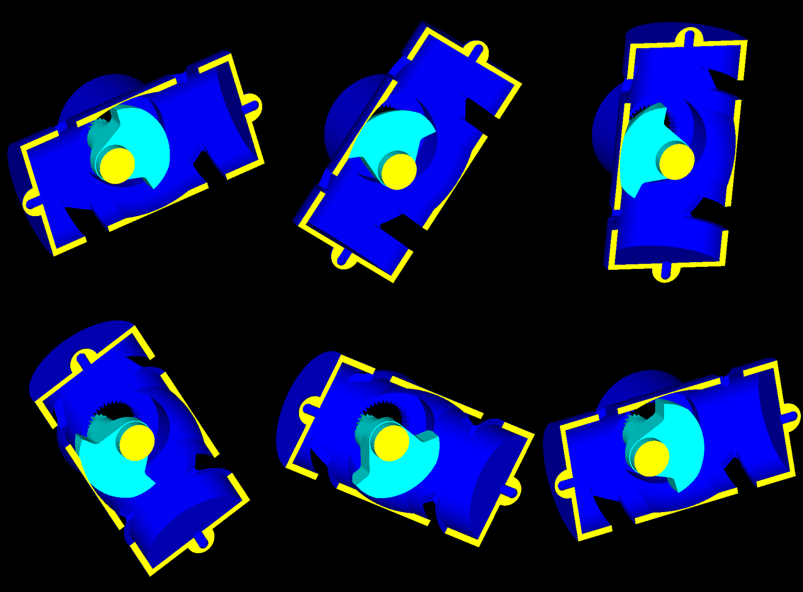
In the following GIF_video_animation:

PatRon_GIF_Video_2.gif

the piston have been removed to show the spinning crankshaft and the spinning cylinder.
The only orbiting thing in this video is the crankpin.


The previous GIF_videos at slow motion are at

http://www.pattakon.....deo_1_Slow.gif

and

http://www.pattakon.....deo_2_Slow.gif


Here is another GIF video-animation showng the spinning crankshaft and the orbiting-spinning piston (the piston head is from a Honda C50):

PatRon_GIF_Video_3.gif

The same video-animation in slow motion is at http://www.pattakon.....deo_3_Slow.gif

Thanks
Manolis Pattakos

#14 Kelpiecross

Kelpiecross
  • Member

  • 1,730 posts
  • Joined: October 10

Posted 14 March 2017 - 05:32


The "slow" animation doesn't work for me. If I understand correctly (which I may not) this is a rotary engine where the various conrods (in a multi-cylinder engine) remain aligned with the cylinder - meaning the piston/conrod could be much shorter and possibly in one piece - could be a very practical idea.

#15 manolis

manolis
  • Member

  • 935 posts
  • Joined: May 03

Posted 14 March 2017 - 06:14

Hello Kelpiecros.

You write:
"The "slow" animation doesn't work for me."

Here are the slow_motion animations:

PatRon_GIF_Video_1_Slow.gif

PatRon_GIF_Video_2_Slow.gif

PatRon_GIF_Video_3_Slow.gif


You also write:
"If I understand correctly (which I may not) this is a rotary engine where the various conrods (in a multi-cylinder engine) remain aligned with the cylinder - meaning the piston/conrod could be much shorter and possibly in one piece"

Yes, this is a rotary engine.

A "double acting piston" can be quite short and lightweight (there is no conventional connecting rod, there is no conventional wrist pin, there are no thrust loads with the cylinder liner (the skirts in some 2-stroke versions are to cover / uncovered some ports).

Thanks
Manolis Pattakos

Edited by manolis, 14 March 2017 - 06:16.


#16 manolis

manolis
  • Member

  • 935 posts
  • Joined: May 03

Posted 15 March 2017 - 14:38

Hello all.

The following animations are for a more compact version of the PatRon 2-stroke direct injection Diesel for small airplanes etc, mentioned in previous posts.

For the same bore (120mm) and piston stroke (60mm) the maximum dimesnion of the rotating cylinder is only 280mm (11 inches).

The cylinder head to cylinder head distance is 240mm.

The piston crown to piston crown distance is 180mm.


PatRon_Air_1.gif

PatRon_Air_2.gif

PatRon_Air_3.gif

PatRon_Air_4.gif

The slow motion animations are at:

http://www.pattakon...._Air_1_Slow.gif

http://www.pattakon...._Air_2_Slow.gif

http://www.pattakon...._Air_3_Slow.gif

and

http://www.pattakon...._Air_4_Slow.gif


Thanks
Manolis Pattakos

Edited by manolis, 15 March 2017 - 15:30.


#17 Pierce89

Pierce89
  • Member

  • 189 posts
  • Joined: December 15

Posted 26 March 2017 - 02:41

Magnolis, I admire your creativity, but if you want any of your engines to succeed, you'll need to drop the scattergun cad approach and actually build and develop whatever you consider to be your most promising idea.

#18 manolis

manolis
  • Member

  • 935 posts
  • Joined: May 03

Posted 27 March 2017 - 04:08

Hello Pierce89

You write:
"Magnolis, I admire your creativity, but if you want any of your engines to succeed, you'll need to drop the scattergun cad approach and actually build and develop whatever you consider to be your most promising idea."


Thanks.

If you talk for the PatRon rotary engine, the idea is quite “fresh”.

If not, there are several (others fully functional and road tested, others functional, others proof of concept) prototypes of the various pattakon projects at http://www.pattakon.com .


The 3D drawings and animations for each project are intended to explain to the technically oriented “skilled in the art” the way of operation, asking for “objections – opinions”.

Why?
Because a second independent "eye" looking at a new engine or mechanism is invaluable.


Unfortunately, and despite the big number of animations, drawings, video-animations, only few people really understand.


Take the PatRon project, for instance.
It is presented in six different "Strictly Technical" forums in the Internet.
Judging from the “responses”, it seems that only a couple of guys have, so far, really understood how it works.
The rest, in the best case repeat some “stereotypes”, in the typical case complain that the PatRon rotary engine is too “mind boggling” to deal with.


Or take the PatRoVa rotary valve (after the UK patent, in a few weeks a US patent is also to be granted for it (the mail of allowance has been already received)).
Even the Patent Examiners of reputable Patent Offices (i.e. engineers who are specialized, for years, in this specific (and narrow) technical field) failed to understand with the first effort how much different the PatRoVa rotary valve is from all other rotary valves of the Prior Art.


So, are there any technical "thoughts / objections" about the PatRon rotary engine?
We do know it is not the "panacea", however, in some applications, it seems having significant advantages.

Or about the PatRoVa rotary valve at http://www.pattakon....akonPatRoVa.htm ?

Thanks
Manolis Pattakos

#19 Kelpiecross

Kelpiecross
  • Member

  • 1,730 posts
  • Joined: October 10

Posted 27 March 2017 - 04:45


I am bloody sure that I don't fully understand a lot of it.

Advertisement

#20 Kelpiecross

Kelpiecross
  • Member

  • 1,730 posts
  • Joined: October 10

Posted 04 April 2017 - 06:05

After a couple of weeks of on-and-off puzzling I think I finally see how it all works. I don't know if this is an already known mechanical principle or not - but it is certainly bloody clever. The way the crankpin follows the cylinder around while remaining on the cylinder's centreline is amazing. However I still doubt its practicality as a useable engine.
It did occur to me that a rearrangement of the engine so that the cylinder remained stationary and the centreline of the crankshaft rotated in the opposite direction could be more useful. This would still give the permanently straight conrod but I don't think it would still be a rotary engine.
The rearrangement also allowed me to understand the rotating version better - and to see that it could not be multi-cylinder off the one crankpin.

Edited by Kelpiecross, 04 April 2017 - 06:06.


#21 gruntguru

gruntguru
  • Member

  • 7,642 posts
  • Joined: January 09

Posted 05 April 2017 - 23:38

I thought about that too but it doesn't have the balance of the rotary version.


#22 manolis

manolis
  • Member

  • 935 posts
  • Joined: May 03

Posted 06 April 2017 - 04:08

Hello Kelpiecross

Nice to hear you got it: i.e. how the PatRon mechanism operates.
Only few did, so far.


The Harmonic PatTwo engine at http://www.pattakon....takonPatTwo.htm :

PatTwo_Harm1.gif

can be seen as “the non rotary version” of the following PatRon:

PatRon_PatTwo.gif


QUOTE from http://www.pattakon....takonPatRon.htm :

With the PatRon:

* the power passes directly to the load,

* the synchronizing gearing remains unloaded by the high gas pressures during the compression - combustion - expansion,

* the two halves of the "immovable" casing (one per side of the spinning cylinder) are easily coupled / bridged forming a space wherein the cylinder spins safely,

* only one crankshaft is required (and only a set of balance webs secured on the crankshaft for the complete balancing of the engine),

* there are no high speed bearings loaded by heavy inertia loads”

END OF QUOTE


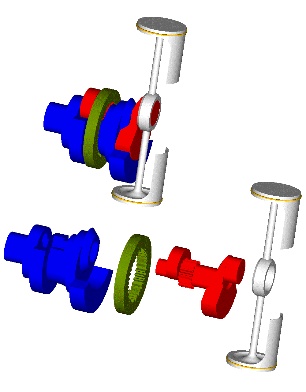
In the Harmonic PatTwo of the animation the gas pressure force passes from the piston crown to the linearly reciprocating pin at the center of the rod connecting the two piston crowns.

This force causes the rotation of the secondary crankshaft of the PatTwo (the red part that spins and orbits), loading at the same time the teeth of the red and green gearwheels.

Then the force received by the secondary crankshaft (red part) passes (through “double speed” bearings) to the primary crankshaft (blue) and to the load.


So, each arrangement has its own advantages.

For instance, a direct injection 2-stroke Diesel PatRon as in the animations in previous posts (with, say, 120mm bore, 60mm stroke, 1,357cc capacity) seems capable for way higher specific power (power to weight ratio) and at the same time for top fuel efficiency, which (together with the perfect balancing, the compact design etc) make it seem a good choice for airplanes / helicopters / flyers (say, like the PAL-V or the Martin JetPack).


Hello Gruntguru.

You write:
“I thought about that too but it doesn't have the balance of the rotary version.”

The non-rotary Harmonic PatTwo of the animation, even in the single cylinder version, even in the single-sided version, is perfectly balanced : zero free inertia force, zero free inertia moment and zero free inertia torque (say, as the Wankel rotary, or not worse than the best V-12).

It is interesting how the inertia torque is eliminated: as the piston decelerates approaching a TDC its kinetic energy reduces; at the same time the balance web of the secondary shaft accelerates and its kinetic energy increases; the sum of the two kinetic energies remains constant giving zero free inertia torque.

Thanks
Manolis Pattakos

#23 gruntguru

gruntguru
  • Member

  • 7,642 posts
  • Joined: January 09

Posted 06 April 2017 - 07:37

So - what is the advantage of the rotating cylinder version? It certainly has several disadvantages.


#24 manolis

manolis
  • Member

  • 935 posts
  • Joined: May 03

Posted 06 April 2017 - 13:58

Hello Gruntguru

You write:
“So - what is the advantage of the rotating cylinder version? It certainly has several disadvantages.”


QUOTE from the specification of the PatRon patent application:

However the harmonic reciprocating piston engines of the closest prior art (*** it means the Harmonic PatTwo engine, among others ***) have some significant drawbacks, too, like:

The bi-directional and heavy loads on the synchronizing gearing during each combustion (which calls, among others, for reliability issues in the long term),

the "indirect" passing of the power from the piston to the load: the force on the piston crown, due to the high pressure gas in the combustion chamber, passes initially to the crankpin of a secondary crankshaft, then (and loading heavily the synchronizing gearing) it passes, through a set of bearings of higher speed, to the power shaft and to the load,

the difficulty in synchronizing the two halves of the "power shaft",

the heavy inertia loads on the "high speed" bearings by which the "secondary" crankshaft is rotatably mounted on the power shaft: these bearings support the assembly of the secondary crankshaft and of the piston (together with the balance webs on the secondary crankshaft),

the need for additional balance webs on the power shaft, etc.

The present invention addresses, among others, the abovementioned problems:
the combustion does not load the synchronizing gearwheels, the power exits
directly to the load, there is no need for a power shaft comprising two
synchronized halves, etc.”

END OF QUOTE.


The problem with the heavy loads on the teeth of the synchronizing gearwheels is met in the LiquidPiston engine, too, as discussed in post #6: the super-over-square “chamber” of the LiquidPiston receives a huge gas pressure force and, due to the design of the engine, it loads heavily the teeth of the gearwheels.


Take the direct injection 2-stroke Diesel PatRon in the post #16, and a similar non-rotary (say, like the PatTwo) version of it.

120mm bore and, say, 100bar peak pressure during the combustion means a peak pressure force of 11tons (110,000N) on the crankpin of the PatRon and on the crankpin of the secondary crank of the PatTwo.

Supposing a high momentum of inertia of the load (which is driven by the crankshaft), the teeth of the two gearwheels of the PatRon remain actually unloaded while the teeth of the two gearwheels (ring gear / spur gear) of the PatTwo are loaded by several tons of force. Besides the frictional loss, it is also the longevity of the engine (if the teeth of the gearwheels start wearing, the resulting backlash when the piston passes from a TDC makes the load impact and accelerates the further wear).


In the Harmonic PatTwo there are two crankshafts: the secondary and the main crankshaft (or power shaft). The secondary crankshaft spins and orbits, with its bearings revving at double speed. The orbiting motion (and the necessarily heavy assembly of the secondary crankshaft with its balance webs and with the piston) creates strong centrifugal forces. The engine needs a strong secondary crankshaft to receive the heavy loads, but it also needs a lightweight (and with small diameter journals) secondary crankshaft in order to reduce the inertia loads on the double-speed bearings and to lower the relative frictional loss.


Worse even: the single sided support of the secondary crankshaft of the PatTwo.
If, in order to support at both sides the secondary crankshaft, another power shaft at the other side of the cylinder is mounted, it is required a set of four gearwheels (like the 2B, 3B, 7A, 7B in the following drawing) to synchronize the two halves of the power shaft and keep them perfectly aligned (otherwise the secondary crankshaft falls apart).
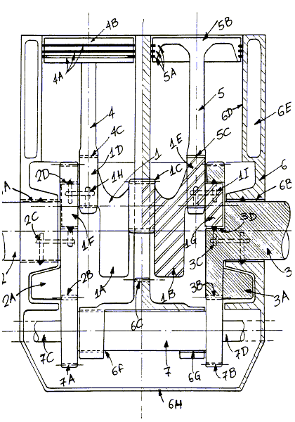
HARMO2.gif

More gearwheels and shafts means more friction, higher cost, more weight, more wear etc.


Or, see how straightly / directly / immediately the gas pressure force on the piston passes to the load of the PatRon without loading anything (neither the cylinder liner, as happens in the conventional engines, nor the synchronizing gear wheels, as happens in the PatTwo and in the LiquidPiston).
In comparison, in the PatTwo the gas pressure force passes initially to the secondary crankshaft and to the gearwheels, and then, through the double-speed bearings, it passes to the power shaft and to the loads. More passages of the energy means more frictional loss.


For several applications the spinning cylinder is a problem (or seems like a problem).

However with the spinning – and rid of thrust loads – cylinder of the PatRon, the cylinder can be made thinner and more lightweight, keeping its cylinder more cylindrical than the cylinders of the conventional engines with the thrust loads.

With the over-square design (120mm bore x 60mm stroke; the bore to stroke ratio is just a bit higher than in the Ducati Panigale 1299) the maximum dimension of the rotating cylinder is 280mm (a typical flywheels is of bigger diameter).

The spinning cylinder gives the opportunity for a built-in aircooling and for automatic scavenging without a scavenge pump.


The characteristics of the 2-stroke PatRon di Diesel of post #16 talk:

for several times smaller weight than an equal power conventional 4-stroke Diesel,

for higher fuel efficiency (better shape of the combustion chamber, more time for the preparation and combustion of the diesel fuel, way lower frictional losses (it is a 2-stroke rid of thrust loads on its cylinder liners, which means a specific lube consumption similar to that of the four strokes and similarly clean exhaust), low pumping loss, etc)

for perfect balancing,

for compact design,

for smaller cost, etc.


It seems as an ideal power unit for small airplanes, helicopters, flyers etc, even for power generator sets (imagine the PatRon in a cage fed with filtered air for both, aircooling and breathing, and driving an electric generator directly secured on its crankshaft).


Thoughts?

Objections?

Thanks
Manolis Pattakos
#25 MatsNorway

MatsNorway
  • Member

  • 2,822 posts
  • Joined: December 09

Posted 06 April 2017 - 19:33

Show us more of this one please. This one is very interesing. As a four stroke ofc. :p


Would like to see more of the red piece and its interaction with the blue.


Remove bearings and sylinder walls etc. If you can show us how the sylinder pressure is transferred over similar to that wonky wankel/Liquid piston engine you designed,   that would be great.

PatTwo_Harm1.gif


Edited by MatsNorway, 06 April 2017 - 19:47.


#26 manolis

manolis
  • Member

  • 935 posts
  • Joined: May 03

Posted 08 April 2017 - 11:09

Hello MatsNorway

You write:
“Show us more of this one please. This one is very interesing. As a four stroke ofc.”


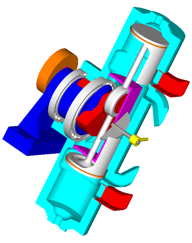
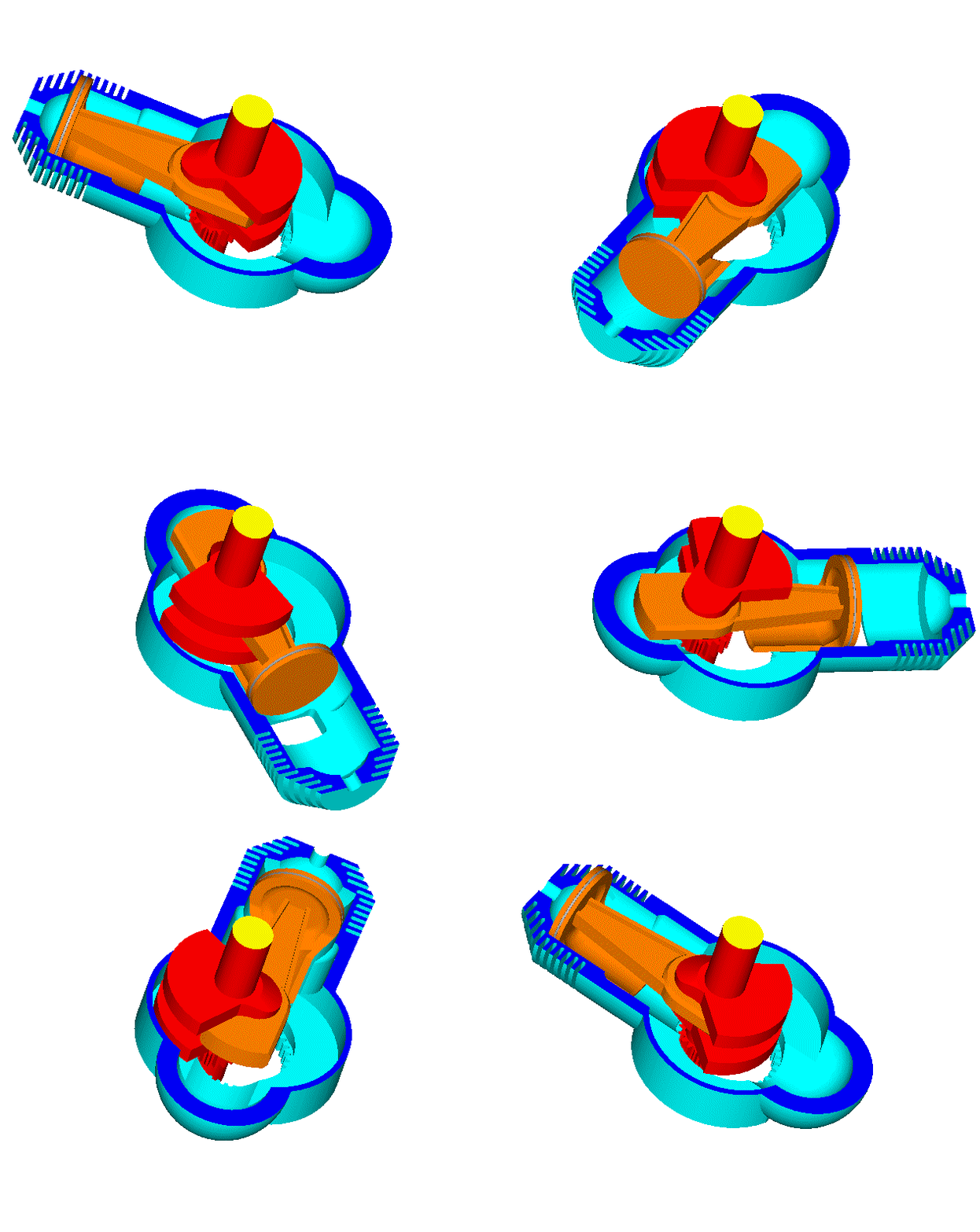
The mechanism is used in the first PatRoVa prototype (a four stroke engine with rotary valve on the cylinder head and the harmonic mechanism at its bottom):


Here are a few pictures of it:

PatRoVa_photo5.jpg

PatRoVa_photo6.jpg


You also write:
“Would like to see more of the red piece and its interaction with the blue.”
Remove bearings and sylinder walls etc. If you can show us how the sylinder pressure is transferred over similar to that wonky wankel/Liquid piston engine you designed, that would be great.”


Here is the drawing without the bearings, the cylinder etc:

PatTwo_Harm_Mats_1.gif


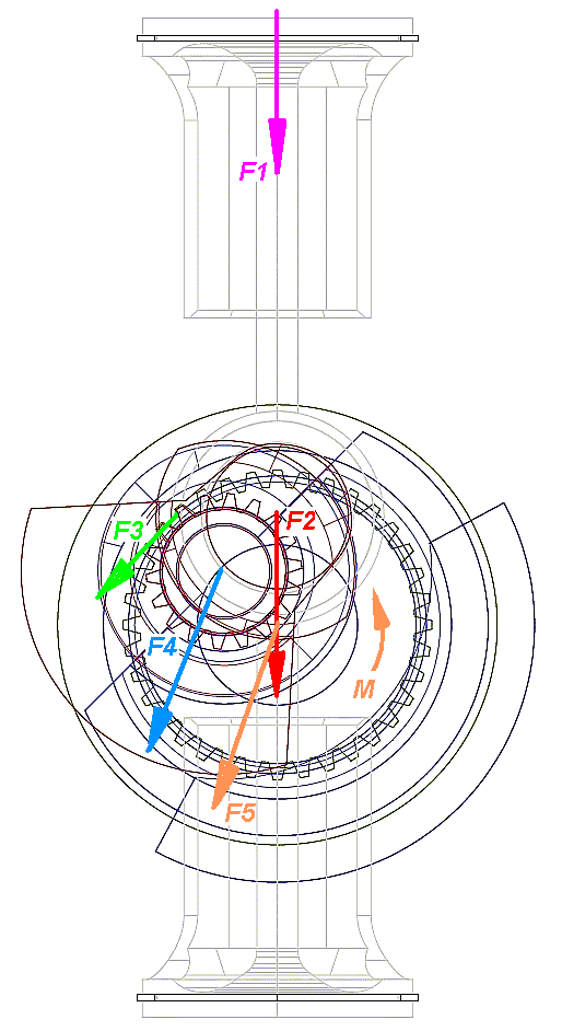
And in this plot they are shown the forces, simplified:

PatTwo_Harm_Mats_2.gif

The gas pressure force F1 (purple) on the piston crown is transmitted (by the piston rod and the bearing) onto the eccentric pin of the secondary crankshaft as an equal force F2 (red).

A force F3 (green) from the teeth of the immovable ring gear to the teeth of the spur gear of the secondary crankshaft is required to cancel out the torque of the F2 force about the center of the secondary crankshaft.
The F3 is about 70% of the F1, because, at the specific angle shown (45 degrees after the TDC), the F3 is at an about 40% longer eccentricity from the center of the secondary crankshaft than the F2.

The F4 force (blue) is the sum of the F2 and F3 forces acting on the secondary crankshaft. The double-speed bearing of the main shaft whereon the secondary crankshaft is rotatably mounted, has to apply an equal and opposite force onto the secondary crankshaft.

The F4 is substantially bigger than the initial force F1 acting on the piston crown.

The F4 acting on the main shaft (or power shaft) of the engine loads the basic bearings of the main-shaft by an equal force F5 and causes the torque M which is finally applied to the load.


All the previous without taking into account the single-sided support of the secondary crankshaft.


Feel free to ask any further explanations.


On the other hand, what is really important in the PatTwo, is not the kinematic mechanism (which is known before 1900).

The important is the highly unconventional breathing of the PatTwo engine.
(more at http://www.pattakon....takonPatTwo.htm )

Thanks
Manolis Pattakos
#27 manolis

manolis
  • Member

  • 935 posts
  • Joined: May 03

Posted 09 April 2017 - 04:56

Hello all.


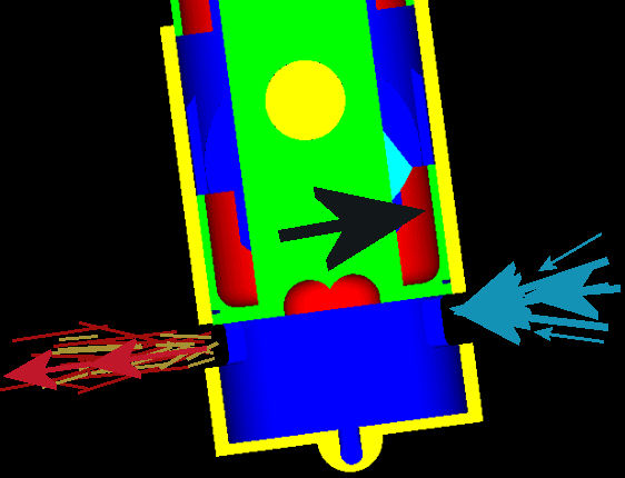
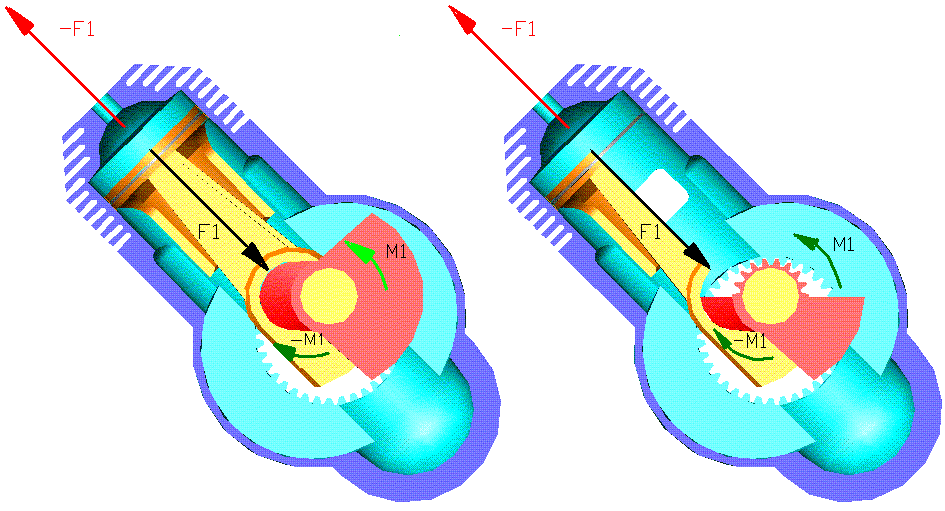
In comparison to the loads in the Harmonic PatTwo (last post), in the following drawing it is shown a single cylinder PatRon and the gas pressure forces when the piston is “45” degrees (measured on the rotating cylinder) after the TDC.

PatRon_Loads.gif

At right the piston and the crankshaft are sliced to show the small gear of the crankshaft.


The high pressure of the gas inside the combustion chamber applies a force F1 (black arrow) on the piston crown.

Due to the geometry of the design, this force necessarily passes from the center of the crankpin.


An equal and opposite force –F1 (red arrow) is applied by the high pressure gas onto the cylinder / cylinder head.

Due to the geometry of the design (again), this force –F1 passes from the rotation axis of the cylinder (which means, the cylinder receives no torque).


When the load is driven by the crankshaft, the torque M1 of the force F1 relative to the rotation axis of the crankshaft is applied on the load (which, in turn, applies an equal and opposite torque –M1 on the crankshaft, leaving the cylinder unloaded by torque).


Take into account the support of the crankshaft at both sides of the engine:

PatRon_Model_parts.gif

(note: the green parts are secured / bolted on the immovable beige part which is the basis of the engine).

take also into account the half crankshaft throw (1/4 of the piston stroke) and the double speed of the crankshaft,

PatRon_Model.gif

take also into account the rid of thrust loads architecture (the cylinder liner takes no forces from the piston skirt),

take also into account the rid of loads synchronizing gearing (the ring gear on the cylinder, the spur gear on the crankshaft),

take also into account the perfect balancing without other balance webs than those on the crankshaft (which are lightweight because the eccentricity of the crankpin is half),

and you have a very interesting direct injection Diesel for airplanes, helicopters, electric generators etc


Thoughts?

Objections?

Thanks
Manolis Pattakos