Jump to content


Photo
- - - - -

PatBalDan: "fixed" ball universal joints exceeding 60 deg operating angle


  • Please log in to reply
4 replies to this topic

#1 manolis

manolis
  • Member

  • 935 posts
  • Joined: May 03

Posted 17 February 2019 - 10:13

Hello all


The PatBalDan, a "fixed" CVJ (Constant Velocity Joint) / Universal Joint of the ball type, is a 100% "constant velocity" joint capable for operating angles well exceeding the 60 degrees (the current world top is 54 degrees).


To the question: 
 
"Why the larger operating angles are preferable / significant / important?"
 
it replies the following quote from the officially published (2007) TECHNICAL REVIEW No.75 of NTN (one of the largest, worldwide, maker and supplier of car CVJ's and car transmission parts): 
 
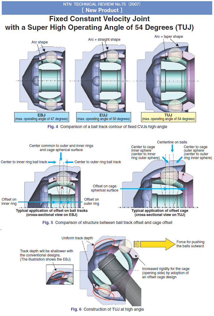
"Fixed Constant Velocity Joint with Super High Operating Angle of 54 Degrees 
. . . 
This maximum operating angle (54 degrees) for automotive driveshaft is currently the highest in the automotive industry. 
The increase of 4 degrees in operating angle means that the minimum turning radius of an average medium-sized FF car can be decreased by approximately 70cm (13%) or the wheelbase of such class of a car can be enlarged by approximately 40cm (15%) while maintaining a minimum turning radius.
In other words, a medium-sized can feature a turning radius of a compact car or the passenger space of a larger car allowing designers more flexibility in consideration of layout and design" 
 
End of Quote 
 
 
Where the limitation of the maximum operating angle of the ball CVJ's comes from?
 
As the angle of the universal joint increases, the shaft secured to the inner race member hits on (or collides with) the tracks formed on the outer race member. From another viewpoint: at the greater operating angles, the tracks of the outer race member "cut" the second shaft limiting its diameter. 
 
For instance: 
With "arc-shaped" tracks, for a bending angle of 54 degrees each track on the outer race member needs to extend angularly for at least 54/2=27 degrees at each side of the bisecting plane of the angle formed by the rotation axes of the two shafts. At the maximum operating angle between the shafts (54 degrees), the one end of the track on the outer race covers 27+54=81 degrees, leaving the rest 9 degrees for the second shaft to pass, which means a total of 2*9=18 degrees "free" space for the second shaft to pass, which degreases substantially the diameter (and the strength) of the joint. With a, say, 70mm diameter of the arcshaped grooves, 18 degrees correspond to maximum possible second shaft diameter of 11mm (70mm*sin(18/2)=10.95mm). 
 
This explains the need for unconventionally shaped tracks (arc+linear or arc+taper) in order to achieve larger operating angles (50 degrees in the first case, and the world top 54 degrees in the second case). 
 
According the previous quote and calculations, the state-of-the-art automotive CVJ is impossible (geometrically) to operate with an angle of 60 degrees between its shafts. 
 
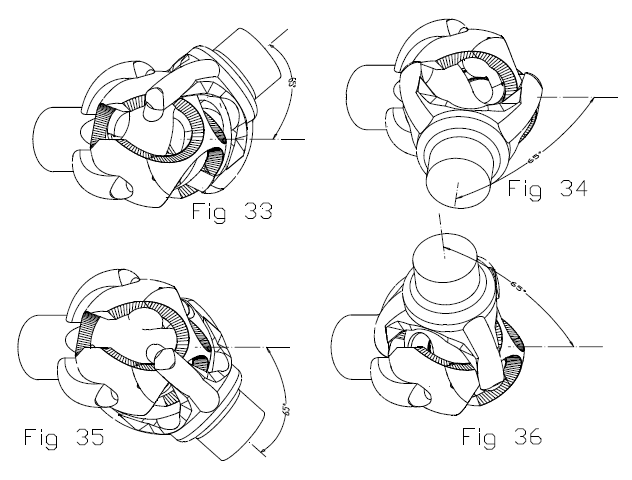
The PatBalDan CVJ (or universal joints) 
 
PatBalDan_15.png
 
is capable, among others, for substantially higher bending angles, even for over 80 degrees (which is 50% larger than the current world maximum). And this can be done with any kind of tracks and/or offset (curved, curved+linear, curved+taper, axial offset, angular offset, cage offset etc). 
 
According the "rule of thump" mentioned in the previous quote, with each 4 degrees larger operating angle, the turning radius reduces by 0.7m or the wheelbase increases by 0.4m. 
 
Applying the above "rule of thump" on a medium size car equipped with the "Super High Operating Angle of 54 Degrees" CVJ's", the replacement of the CVJ's by CVJ's made according the present invention and having, say, 74 degrees operating angle (74=54+5*4) will reduce the turning radius by 5*0.7m=3.5m or thewheelbase will increase by 5*0.4m=2m. 
 
A long-big car propelling its front wheels through PatBalDan CVJ's has, among others, smaller turning radius than a substantially smaller car, can U-turn in narrower roads, can follow narrower/steeper paths and can be parked substantially easier. 
 
End of Quote.


As NTN claims for their TUJ cvj (that with the "Super High Operating Angle of 54 degrees" ):
 
1. Maximum operating angle: 54 degrees
2. Functions (strength and durability): equivalent to those of conventional fixed CVJs.
3. Transmission of torque is possible even at an operating angle of 54 degrees.
 
NTN_TUJ.png
 
 
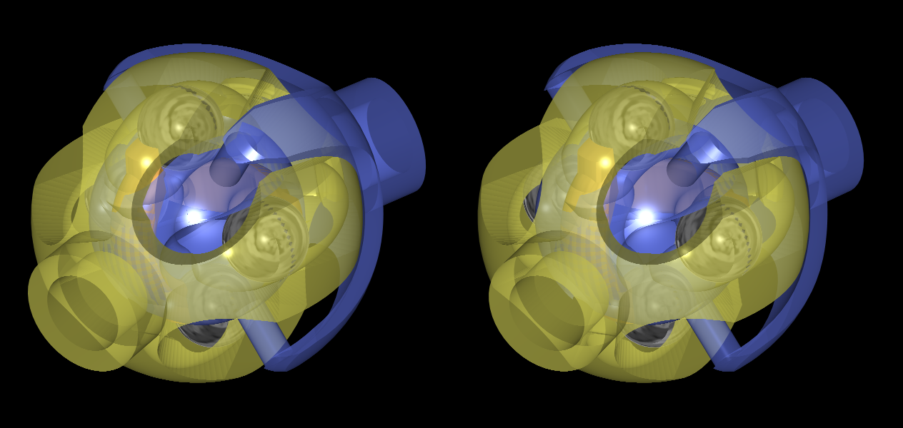
Here are two stereoscopic drawings of a PatBalDan CVJ comprising four balls and two seesaws:
 
PatBalDan.png
 
PatBalDan2.png
 
 
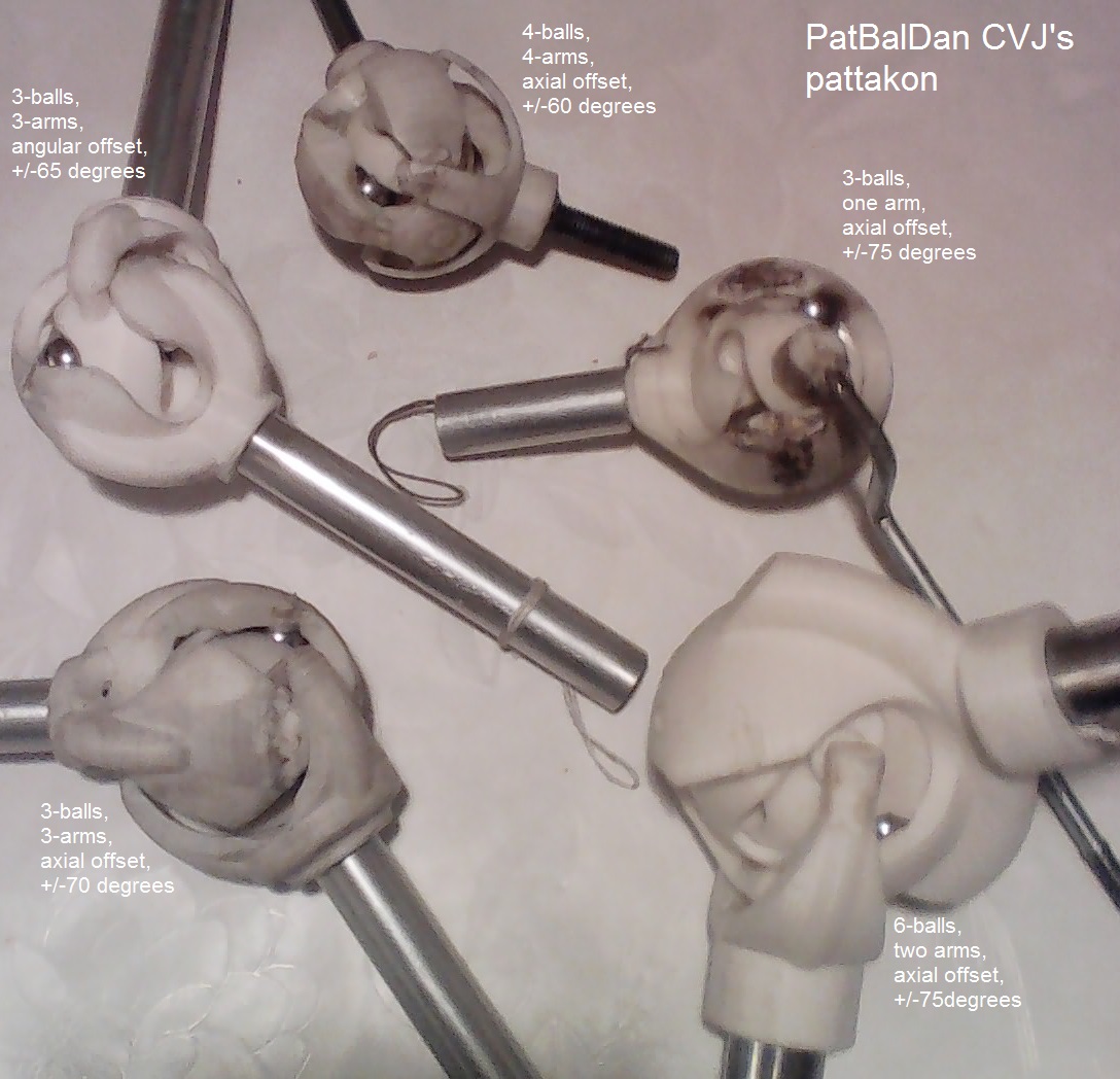
And here is a photo of five functional 3D-printed PatBalDan prototypes:
 
PatBalDan_3D_print_functional_prototypes


Thanks
Manolis Pattakos


Advertisement

#2 Greg Locock

Greg Locock
  • Member

  • 6,363 posts
  • Joined: March 03

Posted 18 February 2019 - 01:13

That would be very useful in steering columns. Getting the UJ angles optimised is a cause of constant aggravation (3 UJs floating in space with different pahsing for each one).


I'm sure you are aware of this but the torque capacity looks rather low compared with more conventional designs.


Well done anyway, very interesting.


#3 manolis

manolis
  • Member

  • 935 posts
  • Joined: May 03

Posted 18 February 2019 - 08:51

Thank you, Greg.


You write:

“That would be very useful in steering columns. Getting the UJ angles optimised is a cause of constant aggravation (3 UJs floating in space with different pahsing for each one).”


Interesting application; with three PatBalDan in series, the “direction” of the rotation can change more than 180 degrees (like “U turn”).


You also write:

“I'm sure you are aware of this but the torque capacity looks rather low compared with more conventional designs.”


The following drawing shows the one shaft of a PatBalDan side-by-side with the NTN-TUJ:
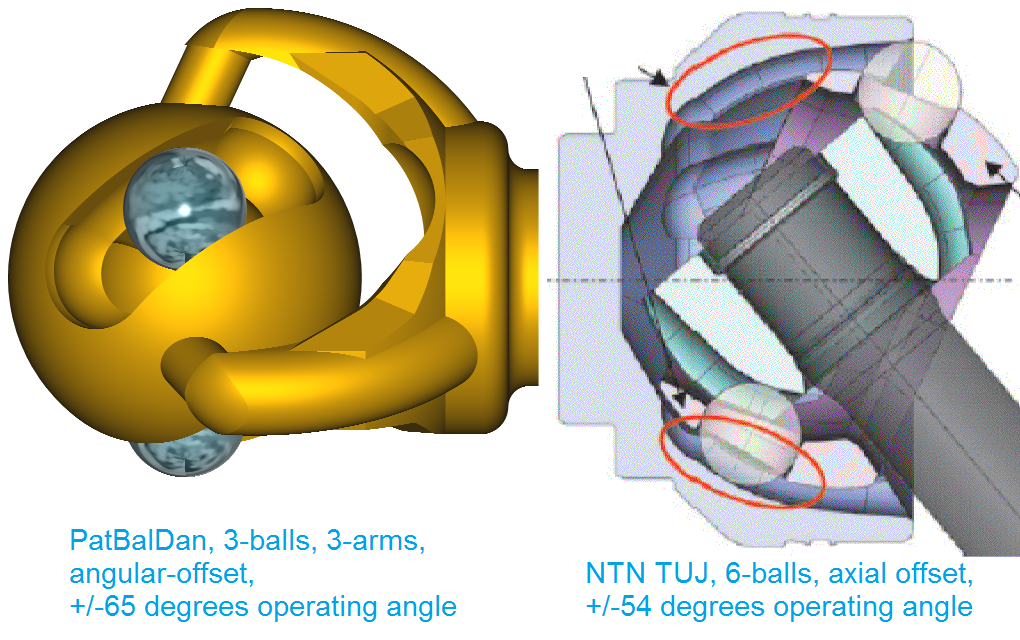
 

PatBalDan3_3_a_vs_NTN_TUJ.png


For the same external dimensions, the balls of the PatBalDan are substantially larger.


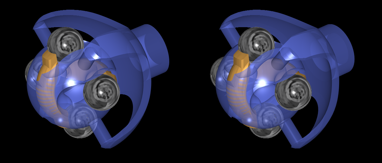
Here is the “cage” (“cage” in the meaning that it keeps permanently the ball centers on a plane passing through the center of the joint) of the above “angular offset” PatBalDan:
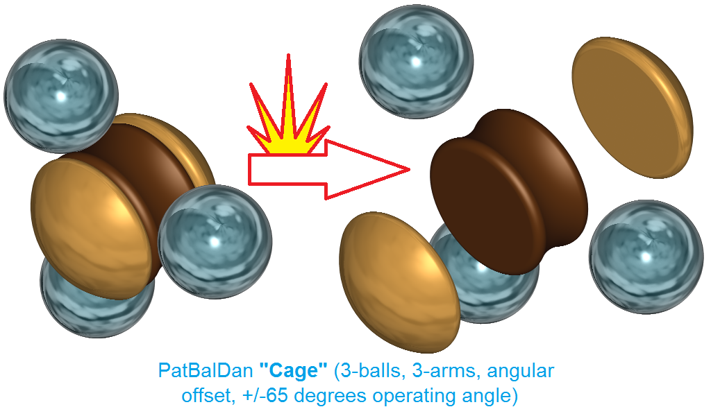
 

PatBalDan3_3_a_Cage.png


With angular offset, the centers of the balls remain at constant distance from the center of the joint, while with “axial offset” the distance of the centers of the balls from the center of the joint vary during a rotation of the shafts.


In the above “cage”, an unconventional and interesting characteristic is that the balls keep “linear contact” with their “cage”, while in the “axial offset” CVJs the balls cannot help “point contact” with their cage.


The fewer but larger balls, and the “linear contact” talk for increased torque capacity.


Thanks

Manolis Pattakos


#4 Greg Locock

Greg Locock
  • Member

  • 6,363 posts
  • Joined: March 03

Posted 18 February 2019 - 10:07

I was comparing the spindly arms with the cup geometry of a 6 ball Rzeppa, but I guess you add an outer sphere to the spindly arms to get a cup. Does that make sense?


#5 manolis

manolis
  • Member

  • 935 posts
  • Joined: May 03

Posted 18 February 2019 - 17:06

Hello Greg.


Yes, if necessary the "arms" (or fingers) can be bridged / webbed by an outer spherical cup.


Some other PatBalDan designs are already like "spherical cups".


The following animation shows from various view-points the "outer race member" of a: 3-ball, single-arm, axial-offset, +/-75degrees PatBalDan:
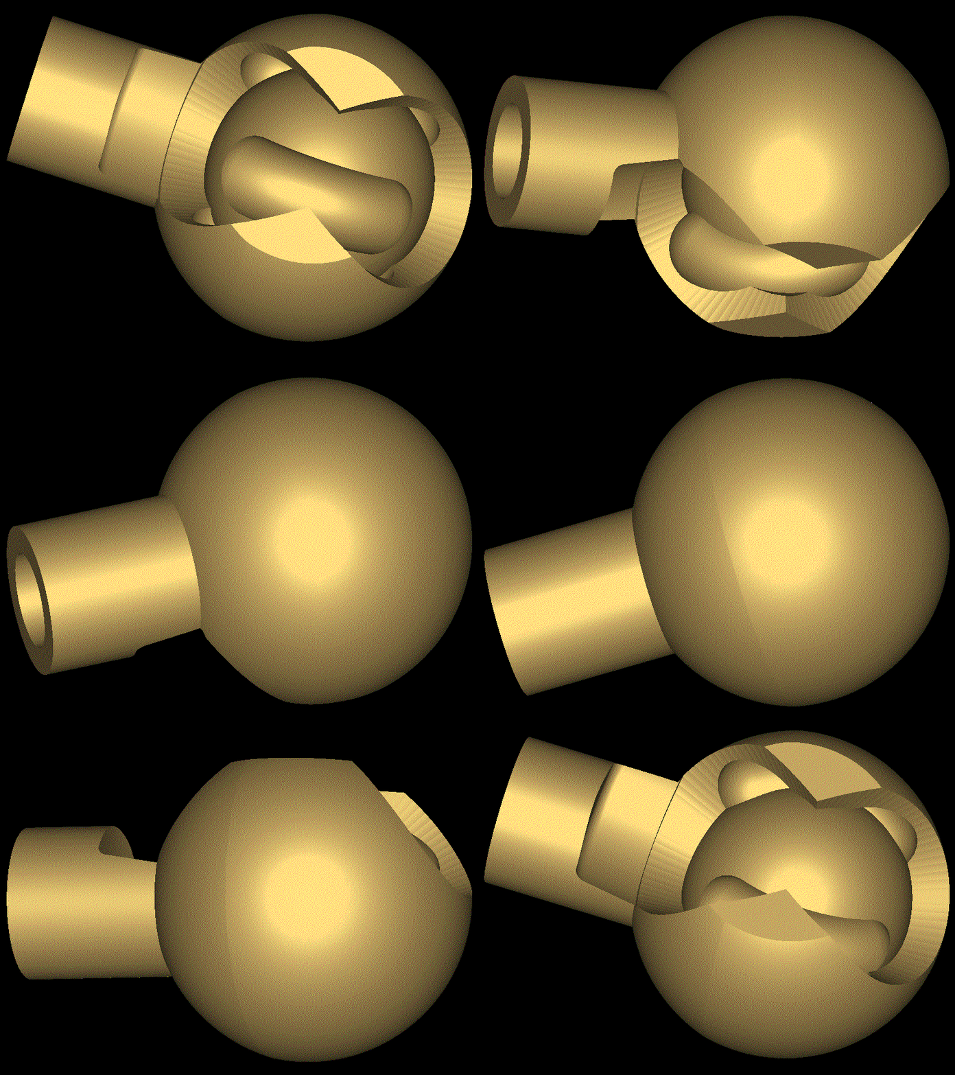
 

PatBalDan_3_1_axis_75.gif


EDIT:


Here is the NTN_TUJ for comparison:
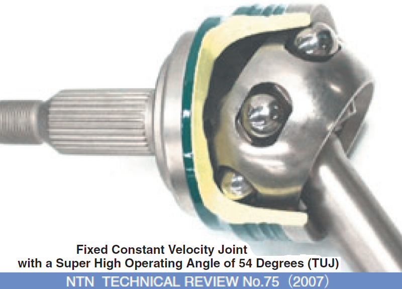
 

NTN_TUJ_B.png


In both cases the "outer race member" is a "spherical cup".


The difference is in the direction of the opening of the spherical cup: in the conventional CVJ the opening is arranged oppositely to the shaft, while in the above PatBalDan version the opening of the "spherical cup" is arranged "perpendicular" to the shaft.


I think it is more clear now.


Thanks

Manolis Pattakos


Edited by manolis, 19 February 2019 - 05:08.