
1) A dual V12 crank, like the following pattern:

Arms 1 & 2 are at 0 degrees and correspond with cylinders 1-13 and 12-24.
Arms 3 & 4 are at 60 degrees and correspond with cylinders 2-14 and 11-23.
Arms 5 & 6 are at 120 degrees and correspond with cylinders 3-15 and 10-22.
Arms 7 & 8 are at 180 degrees and correspond with cylinders 4-16 and 9-21.
Arms 9 & 10 are at 240 degrees and correspond with cylinders 5-17 and 8-20.
Arms 11 & 12 are at 300 degrees and correspond with cylinders 6-18 and 7-19.
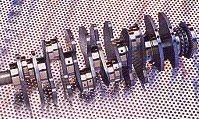
2) The crank arms will look like spokes 18, 1 and 2 in the image. Where the spokes intersect will be the crank centre.

Arms 1 & 2 are at 0 degrees and correspond with cylinders 1-13 and 12-24.
Arms 3 & 4 are at 30 degrees and correspond with cylinders 2-14 and 11-23.
Arms 5 & 6 are at 60 degrees and correspond with cylinders 3-15 and 10-22.
Arms 7 & 8 are at 180 degrees and correspond with cylinders 4-16 and 9-21.
Arms 9 & 10 are at 210 degrees and correspond with cylinders 5-17 and 8-20.
Arms 11 & 12 are at 240 degrees and correspond with cylinders 6-18 and 7-19.
Both crank (1) and (2) appear to be equally balanced in the first order (initially at least) and move their respective cylinders equally in relation to each other i.e both cranks will place cylinders at both ends of a bank in the same position. This is unlike flat-plane and cross-plane cranks for V8 engines, in which only the flat-plane crank matches cylinders end to end in a bank.
I'm thinking if however crank (2) will generate second order vibrations as in a flat-plane V8 crank?
Does anyone know why the following WR12 cranks are different?


The first two look more robust and have typical 'uniform' counterweights, while the third has pieces cutout of some of the counterweights?
Obi


