Hi all,
In the mid to late 1960s several F1 and F2 racecars used what I called 'ducted windscreens'. These included several Lotus cars (33 and 49 amongst others) and Matra F2 cars.
I recall an explanation at the time about generating a jet stream to deflect rain, dust and debris over the drivers head.
In the light of what we now know about aerodynamics, I wonder what they actually achieved and why they fell out of use. At the time, and especially with the advent of full-width noses, I wondered why similar ducts were not used to deflect airflow around the front wheels.
Anyone got any comments?
Cheers
Pat

Ducted windscreen
Started by
Pat Clarke
, Feb 15 2009 07:54
32 replies to this topic
Advertisement
#2

OfficeLinebacker
-

- 14,088 posts
- Joined: December 07
Member
Posted 15 February 2009 - 14:43
Got any pics?
#3
macoran
-

- 3,989 posts
- Joined: August 05
Member
Posted 15 February 2009 - 22:32
Originally posted by Pat Clarke
Hi all,
In the mid to late 1960s several F1 and F2 racecars used what I called 'ducted windscreens'. These included several Lotus cars (33 and 49 amongst others) and Matra F2 cars.
I recall an explanation at the time about generating a jet stream to deflect rain, dust and debris over the drivers head.
In the light of what we now know about aerodynamics, I wonder what they actually achieved and why they fell out of use. At the time, and especially with the advent of full-width noses, I wondered why similar ducts were not used to deflect airflow around the front wheels.
Anyone got any comments?
Cheers
Pat
I have this bit from an article in MOTOR magazine w/e January 15th 1966

as well as the relevant part of the interview by Charles Bulmer with Colin Chapman

#4
Stefan_VTi
-

- 123 posts
- Joined: January 04
Member
Posted 15 February 2009 - 23:36
The Renault Spider has this as well:

#5
NRoshier
-

- 506 posts
- Joined: September 06
Member
Posted 16 February 2009 - 00:16
works with air and thing with same mass as air, but air curtain will still be penetrated by items with mass significantly greater than air...eg flys or stones etc...which then still impact occupants at original velocity...also works best at certain speeds.
#6
JtP1
-

- 753 posts
- Joined: September 08
Member
Posted 24 February 2009 - 11:11
Originally posted by NRoshier
works with air and thing with same mass as air, but air curtain will still be penetrated by items with mass significantly greater than air...eg flys or stones etc...which then still impact occupants at original velocity...also works best at certain speeds.
You are probably correct about stones because Jim Clark regularly used a hankerchief or similar as face protection after the introduction of the aero screen. Lotus must have reckoned it worked, because they kept using it.
Not a Chapman original as he admitted to getting the idea from RN destroyers and the idea obviously worked under 40mph there.
#7
scooperman
-

- 84 posts
- Joined: November 06
Member
Posted 24 February 2009 - 12:44
I always wondered about the duct on the front of the Chaparral 2A, it seemed to end on top of the windscreen.
#8
jatwarks
-

- 202 posts
- Joined: August 08
Member
Posted 26 February 2009 - 12:59
A few comments come to mind.
I seem to remember that the singularly unsuccessful early (?) Ensign F1 car, with the full width nose and excess body panelling, was later shown to be devoid of aerodynamic downforce because, at speed, the nose and bodywork deflected the airflow above the rear wing. I bet the driver had no problem with buffeting!
It's the buffeting, I believe, that the ducting was supposed to reduce. Now, helmet design takes care of that.
I would think that the ducting would be considered a disadvantage now that aero is researched to the nth degree. Designers now like to ensure that the airflow wraps as neatly around the cockpit as possible: And, that the rear wing passes through air as undisturbed as possible.
Also, once engine intake airboxes became common a ducted screen might interfere with the airflow into the engine.
Then again, there was the ducting at the front of the cockpit introduced by Ferrari to feed air into the engine inlets when tall airboxes were banned.
Jim.
#9
Terry Walker
-

- 3,005 posts
- Joined: July 05
Member
Posted 26 February 2009 - 13:56
I'm sure you're right. I recall reading at the time that the ducting acted as a virtual windscreen: the driver could see through the air above the screen, and was protected from buffeting, as you say. As a motorcyclist of decades standing, I can assure you that helmet buffeting in turbulent conditions can be very tiring. If you can have unobstucted, dead-bug-free and oil-slick-free vision AND just a light breeze on your helmet, you're way ahead. These days they don't have windscreens, but the shape of the body (and the very low position of the driver's helmet) get the same result.
#10
NRoshier
-
- 506 posts
- Joined: September 06
Member
Posted 27 February 2009 - 10:03
WRT Pat's original question about current useage with wheels etc, I can't but think that the downstream turbulence would mitigate any potential drag benefit...but I have been badly wrong on aero stuff before.
#11
Paul Vanderheijden
-

- 65 posts
- Joined: December 07
Member
Posted 27 September 2009 - 19:37
I know this is an old post, but I would like to throw a new twist in just to see if anyone has any ideas.
Problem - Historic racer with newly installed aluminum, front radiator running abnormally high coolant temperatures. Engine at the moment is a mild state of tune with approx. 80 HP. Electric water pump (Davies Craig Series 80) running full speed. Pump capacity approx 30 L/min at 6 PSI pressure. Indicated water temperature is 210 degrees, with a 24 lb cap. No boiling. Even though there is an entry to the radiator, and an air exit through the base of what would normally be the battery box and I fear that there is not enough air flow across the radiator core.
________________________________________________________________________________
____________________________
Normally the area at the base of the windscreen would be a high static pressure area. I am working with placing a front mounted radiator in a Fiat 850 Spider. The car itself is a fairly streamlined design, but with the addition of a front mounted radiator, there is a real problem getting adequate pressure differential between the front and rear of the radiator.

As you can see from this photo, this is the radiator opening, with the proposed "sugar scoop" to aid entry of air into the opening. The opening size is 4 x 17 inches.

This the rear side of the radiator. The radiator is a dual row, dual pass unit with the core being approx 12 x 30 inches. The radiator is meticulously sealed so that all air coming in through the air intake area must pass through the radiator. There is deflector/turning vane to duct the air coming through the radiator to either side of the fuel cell. THis has either a air space (in front of the fuel cell) or insulation (sides of the fuel cell).
Now here is the problem. There are really only two options for venting the air coming through the radiator.
1) Remove the bottom of the battery box (hole 7 x 11 inches) and exit the air under the car.

2) Relocate the fire bottle and duct the hot air up through the holes in the hood in front of the windshield. Note: Windshield has been cut down to where it is only 4" tall.


Looking at the design of the front end, I fear that either place has some problems. The under car body shape (reversed wedge) would tend to create an area that has both static and velocity high pressure characteristics. The steering drag link and transverse leaf spring (remember its historic) are directly below the battery box opening and could deflect a portion of the air stream back up into the battery box. Secondly the shape of the body would facilitate a static high pressure area in that same location.
The windshield exit option exits the air into a static high pressure zone in front of the windshield. Is it possible that air is actually being forced back into the luggage compartment at speed?
The historic racing rules will not permit the addition of a full height splitter. However I did consider using a splitter under the car, just forward of the steering drag link, in the same shape as the "V" panel in front of the fuel cell, with the ends curved. It would hang down to the bottom of the drag link. This could create a low pressure area immediately behind it (where the bottom of the battery box opening is) and also this would alleviate any possibility of deflecting any of the underbody air flow back up the opening in the air box.
At the windshield area I had thought of using a variation of the double windshield idea. If there were a horizontal panel aove the holes in the hood by 1 inch, and this panel terminated in a curve upwards and parallel to the 4" windshield (but only about 1.5 inches high) then air travelling over this area might help "scavenge" air out through these holes. Of course the fire bottle would get relocated and the panel where it is currently mounted would either get removed or have some very large holes in it.
At the moment I am doing some verification of the problem by setting up a differential pressure guage in the car, with one tube in front of the radiator and the other in the area behind the radiator. The idea is that we would get a baseline reading before making any changes. This would also allow us to assess how much improvement was gained by each change.
All suggestions and criticisms gratefully accepted.
Paul
Scuderia Topolino.
Problem - Historic racer with newly installed aluminum, front radiator running abnormally high coolant temperatures. Engine at the moment is a mild state of tune with approx. 80 HP. Electric water pump (Davies Craig Series 80) running full speed. Pump capacity approx 30 L/min at 6 PSI pressure. Indicated water temperature is 210 degrees, with a 24 lb cap. No boiling. Even though there is an entry to the radiator, and an air exit through the base of what would normally be the battery box and I fear that there is not enough air flow across the radiator core.
________________________________________________________________________________
____________________________
Normally the area at the base of the windscreen would be a high static pressure area. I am working with placing a front mounted radiator in a Fiat 850 Spider. The car itself is a fairly streamlined design, but with the addition of a front mounted radiator, there is a real problem getting adequate pressure differential between the front and rear of the radiator.
As you can see from this photo, this is the radiator opening, with the proposed "sugar scoop" to aid entry of air into the opening. The opening size is 4 x 17 inches.
This the rear side of the radiator. The radiator is a dual row, dual pass unit with the core being approx 12 x 30 inches. The radiator is meticulously sealed so that all air coming in through the air intake area must pass through the radiator. There is deflector/turning vane to duct the air coming through the radiator to either side of the fuel cell. THis has either a air space (in front of the fuel cell) or insulation (sides of the fuel cell).
Now here is the problem. There are really only two options for venting the air coming through the radiator.
1) Remove the bottom of the battery box (hole 7 x 11 inches) and exit the air under the car.
2) Relocate the fire bottle and duct the hot air up through the holes in the hood in front of the windshield. Note: Windshield has been cut down to where it is only 4" tall.
Looking at the design of the front end, I fear that either place has some problems. The under car body shape (reversed wedge) would tend to create an area that has both static and velocity high pressure characteristics. The steering drag link and transverse leaf spring (remember its historic) are directly below the battery box opening and could deflect a portion of the air stream back up into the battery box. Secondly the shape of the body would facilitate a static high pressure area in that same location.
The windshield exit option exits the air into a static high pressure zone in front of the windshield. Is it possible that air is actually being forced back into the luggage compartment at speed?
The historic racing rules will not permit the addition of a full height splitter. However I did consider using a splitter under the car, just forward of the steering drag link, in the same shape as the "V" panel in front of the fuel cell, with the ends curved. It would hang down to the bottom of the drag link. This could create a low pressure area immediately behind it (where the bottom of the battery box opening is) and also this would alleviate any possibility of deflecting any of the underbody air flow back up the opening in the air box.
At the windshield area I had thought of using a variation of the double windshield idea. If there were a horizontal panel aove the holes in the hood by 1 inch, and this panel terminated in a curve upwards and parallel to the 4" windshield (but only about 1.5 inches high) then air travelling over this area might help "scavenge" air out through these holes. Of course the fire bottle would get relocated and the panel where it is currently mounted would either get removed or have some very large holes in it.
At the moment I am doing some verification of the problem by setting up a differential pressure guage in the car, with one tube in front of the radiator and the other in the area behind the radiator. The idea is that we would get a baseline reading before making any changes. This would also allow us to assess how much improvement was gained by each change.
All suggestions and criticisms gratefully accepted.
Paul
Scuderia Topolino.
#12
gruntguru
-

- 7,706 posts
- Joined: January 09
Member
Posted 27 September 2009 - 23:15
I will kick it off by saying the deflector you have fitted between radiator and fuel cell looks too close to the radiator. I think a flat shield close in front of the fuel cell with the sides rounded to blend into the sides of the fuel cell would work a lot better. Simple check is a quick test drive without any shield at all.I know this is an old post, but I would like to throw a new twist in just to see if anyone has any ideas.
All suggestions and criticisms gratefully accepted.
Paul
The top edge of the air entry looks bad. Air flow coming down the front of the bumper will continue down and pinch off the opening. I will bet the top of the radiator is gettig a lot less air than the bottom. If you can move this edge up and reshape it to create a large radius and encourage air towards the top of the radiator it will likely make a much bigger difference than the sugar scoop.
#13
Greg Locock
-

- 6,494 posts
- Joined: March 03
Member
Posted 28 September 2009 - 00:00
Sounds like a job for a U tube manometer. The dynamic pressure at the front of the car and the base of the windscreen is virtually identical, so that ain't gonna work.
#14
Paul Vanderheijden
-
- 65 posts
- Joined: December 07
Member
Posted 28 September 2009 - 00:07
I will kick it off by saying the deflector you have fitted between radiator and fuel cell looks too close to the radiator. I think a flat shield close in front of the fuel cell with the sides rounded to blend into the sides of the fuel cell would work a lot better. Simple check is a quick test drive without any shield at all.
The top edge of the air entry looks bad. Air flow coming down the front of the bumper will continue down and pinch off the opening. I will bet the top of the radiator is gettig a lot less air than the bottom. If you can move this edge up and reshape it to create a large radius and encourage air towards the top of the radiator it will likely make a much bigger difference than the sugar scoop.
Hello GruntGuru,
One of the early tests to do was precisely that. Instead of the deflector, I had in mind to use two air directors on each side of the fuel cell to guide the air around the 90 deg corner.
Reference the front of the car I was going to do some tests with tufts of wool and a large fan that we have in the workshop. I had always wondered, with a high-waisted body like like is the air deflected downward at the waist would tend to "shear" any air trying to get into the opening.
BTW - on the air exit conundrum the lip that is shown on the opening in the bottom of the battery box has already been removed to form the 7 x 11 inch opening mentioned earlier.
I honestly think that the combination of a high pressure area under the car, and possibly a high pressure area at the windshield, that there may not be any substantive pressure drop between the front and rear of the radiator.
Look forward to more comments.
Paul
#15
Engineguy
-

- 989 posts
- Joined: February 01
Member
Posted 28 September 2009 - 00:52
Is there an opening under the fuel cell? If so, can you raise the front (or all) of the fuel cell an inch or so?
Otherwise, the 1½" tall hood vent lip, out to about the width of the hood pins, with ends bent back about 80° to reduce curl-around re-entry of airflow. I'd think that would move the high pressure pocket forward of the lip, even though the windscreen is a bit higher.
.
Otherwise, the 1½" tall hood vent lip, out to about the width of the hood pins, with ends bent back about 80° to reduce curl-around re-entry of airflow. I'd think that would move the high pressure pocket forward of the lip, even though the windscreen is a bit higher.
.
#16
Paul Vanderheijden
-
- 65 posts
- Joined: December 07
Member
Posted 28 September 2009 - 02:25
Thanks everyone for the suggestions.
Here is the order of things as we will try them.
1) Document the current setup with a u-tube manometer as a base line.
2) Add 3" tall splitter under the car to help in creating a low pressure area. Re-Check with manometer for improvement.
3) If more air flow is needed then a rectangular hole will be made in the floor area to each side of the fuel cell (approx. 6 x 8 inches per side). This will increase the air exit area from 77 square inches to 160 square inches. Document with manometer readings.
4 Once we have the air handling optimised, then I will do some additional tests by varying the pump speeds.
Regards,
Paul
#17
McGuire
-

- 9,218 posts
- Joined: October 03
Member
Posted 28 September 2009 - 03:26
Nice work, first-class craftsmanship.
#18
cheapracer
-

- 10,388 posts
- Joined: May 07
Member
Posted 28 September 2009 - 04:09
On a mobile phone so can't read all the posts nor see all the pics clearly but it looks to me like you have the radiator entry at a high pressure area (the front of the car DUH) and the airflow exit at, wait for it, the other high pressure area at the base of the windscreen. This area at the base of the windscreen is used as an INLET for air, not an outlet.
You need to exit the air just behind the radiator on the bonnet where it starts to fletten it's curve where the air is trying to seperate or behind the front wheel arches.
Just arrived at a terminal, what T3000 said.
Paul, just behind the radiator inside, where do those inner guard hollows run to - can they be used for air extraction?
Edited by cheapracer, 28 September 2009 - 06:23.
#19
zac510
-

- 1,713 posts
- Joined: January 04
Member
Posted 28 September 2009 - 10:26
That looks like a huge radiator for 80hp. Am I being tricked by the aluminium shrouding?
Edited by zac510, 28 September 2009 - 10:27.
Advertisement
#20
NRoshier
-
- 506 posts
- Joined: September 06
Member
Posted 28 September 2009 - 11:32
I'm wary of ducting to under the car if other solutions are possible...this comes from driving an old car that lifts at speed! So can I suggest the following: Radius the corners of the entry to the radiator to maximise the effective area, or if you like minimise turbulence prior to Rad. Also the wheelwells are a prime low pressure zone....can you (within the rules) cut holes in the inner guard to access these? Also get rid of 80% the lip on either side of the 'boot' opening...or try to maximise the effective gap if other things are not allowed in the rules...it is very inefficient as an outlet but it might make a difference.
btw must you have the horrible mesh...it will do nothing for cooling.
btw must you have the horrible mesh...it will do nothing for cooling.
Edited by NRoshier, 28 September 2009 - 11:33.
#21
Paul Vanderheijden
-
- 65 posts
- Joined: December 07
Member
Posted 28 September 2009 - 12:03
That looks like a huge radiator for 80hp. Am I being tricked by the aluminium shrouding?
TC3000
Bringing the exit air into the passenger compartment I do not consider advisable, as there must be a steel firewall between the driver and the fuel cell according to the safety regulations.
After looking at the pressure distribution diagram I had already decided that the best thing would be to install a nicely trimmed aluminum plate over the openings in the luggage compartment lid, and install a seal all around the the luggage compartment lid, so that when it is closed no air could enter or escape the compartment this way. As you say, eliminate any possible short-circuit of the air flow direction that we are looking for.
The additional exit orifices adjacent left and right of the fuel cell, as well as the existing battery box bottom orifice, would all be immediately behind the new air dam under the vehicle. As such they would all be in a "lower" pressure zone. In looking at this would it be best to curve the ends of the air dam around and towards the rear of the car to maintain the lower pressure zone further under the car?
CHEAPRACER
The large holes on either side, on the vertical walls of the compartment, are there for access to the head lights for service. As there are no head lights in this car, the areas are basically "dead space". The panel that you see, looking into the hole, is the top of the inner fender panel. I suppose that a series of holes there would also help, as the wheel-well, according to the Cp diagram, is also a lower pressure area?
zac510
The radiator is a two row core, dual pass unit. Size is 12 x 30. If the air flow can be managed, then yes it should be a very good radiator given the HP. There is a new engine on the way with more HP, but until the cooling issues are addressed it will not be installed.
NRoshier
Thanks for the observations. The mesh in the opening has already been eliminated. Re-contouring the air entry is under consideration, but because of aesthetic/rules this might be problematical. The ideal of using the wheel wells was also mentioned by CHEAPRACER and this is a serious consideration.
I have abandoned the idea of using the vents on the hood in any meaningful way. As I see it at the moment, it may do more harm than good.
McQuire
Thanks for the nice comments. The man who owns the car works in the satellite building business, so I am sure that attention to detail is important.
#22
Joe Bosworth
-

- 687 posts
- Joined: May 05
Member
Posted 28 September 2009 - 12:05
Paul
You are getting a lot of useful advice, particularly relative to not exiting the air into a high pressure area.
But let me raise a couple of items not raised in other replies.
You must have one of the least efficient radiators of all time. At 360 square inch area you are probably about three times the area that is needed for your application. But you don mention the fins per inch which is an important factor.
I don´t know how much open area you have through that radiator but it is likely to be more than 50% of the total area or >180 sq in.
Now by your own admission you are presently exiting through 77 sq in. Don´t you think that a bit small? You say you are increasing that to 160 sq in. Still ???.
But just think about what you are doing with air velocities. High through the radiator. Very low while dumping into the large open area. Then much faster again as you exit through the small openings mentioned above.
And/or, the very small exit openings in a poor pressure area might well be restricting the air volume and therefore velocity through the radiator to such low velocities that the radiator efficiency is nearing zilch. Think in terms of how hot a fanless car gets while outputting large HP at very low speed. I can give you the formulas to calculate how heat transfer rates change by air velocity if you wish.
Few people recognise the importance of maintaining velocity on the exit side by a sealed duct, (in your case you might want to use a bifurcated double duct). Take that duct while still sealed and exit it at the optimum region as others are talking about. A good region might be just behind the wheels.
The exit duct has two benifits. One is relative to radiator efficiency. Te other is a substantial reducti0n in aero Cd.
Regards
#23
Paul Vanderheijden
-
- 65 posts
- Joined: December 07
Member
Posted 28 September 2009 - 14:00
Paul
You are getting a lot of useful advice, particularly relative to not exiting the air into a high pressure area.
But let me raise a couple of items not raised in other replies.
You must have one of the least efficient radiators of all time. At 360 square inch area you are probably about three times the area that is needed for your application. But you don mention the fins per inch which is an important factor.
I don´t know how much open area you have through that radiator but it is likely to be more than 50% of the total area or >180 sq in.
Now by your own admission you are presently exiting through 77 sq in. Don´t you think that a bit small? You say you are increasing that to 160 sq in. Still ???.
But just think about what you are doing with air velocities. High through the radiator. Very low while dumping into the large open area. Then much faster again as you exit through the small openings mentioned above.
And/or, the very small exit openings in a poor pressure area might well be restricting the air volume and therefore velocity through the radiator to such low velocities that the radiator efficiency is nearing zilch. Think in terms of how hot a fanless car gets while outputting large HP at very low speed. I can give you the formulas to calculate how heat transfer rates change by air velocity if you wish.
Few people recognise the importance of maintaining velocity on the exit side by a sealed duct, (in your case you might want to use a bifurcated double duct). Take that duct while still sealed and exit it at the optimum region as others are talking about. A good region might be just behind the wheels.
The exit duct has two benifits. One is relative to radiator efficiency. Te other is a substantial reducti0n in aero Cd.
Regards
JOE BOSWORTH
Joe, thanks you for your insight.
Yes, it has not gone unnoticed that there are some significant disparities in both the static pressures and velocity pressures on this installation. The goal must be to create an environment where the air flow potential behind the radiator is at least equal if not more than the air flow potential in front of the radiator. Only then will there be sufficient flow to effectively take away heat from the radiator core.
Unfortunately, I have to try and deal with this situation under the rather restrictive regulatory environment existing in the historic racing community. The regulators have "reluctantly" allowed the use of a front mounted radiator (even thought the original specific model did not have one) in terms of engine reliability. Unfortunately this did not carry through to making exit ducts in the luggage compartment lid.
Having said that, how can we best use what we do have available. Here are the options that I feel would be acceptable to the regulators.
1. Removal of the screen in front of the air inlet opening, enlarge the opening to 6 x 17 and add a small deflector (scoop) to the bottom edge of the opening to help better organize the air flow. Removal of the screen will lessen the amount of air flow disruption to the air entering the inlet and increasing the size will increase the volume of air.
2. Addition of air exits in the front pan of the luggage compartment on either side of the fuel cell. The two will add approximately 60 square inches on each side, for a total 197 square inches of exit area. Yes, without the addition of #3, this still means that we have a lower pressure area trying to feed into a higher pressure air flow under the vehicle
3. A 3" tall air dam (splitter) will be added to the underside of the luggage compartment, curving around the and extending to the rear edge of the luggage compartment underside . This will place all of the air exit openings immediately behind the air dam.
4. There is an opportunity to ultilize the front wheel wells for additional air exit from the area behind the radiator. The assumption is that this will form an lower pressure area immediately behind the air dam, allowing the air to exit from the the luggage compartment. I would like to hear your view on using this area?
5. If needed, open up the luggage compartment to the inside wall of the front wheel wells. This could add additional low pressure area for the exit air flow to utilize.
The radiator 7 x 18 inches, 2 row, dual pass, with 16 fins per inch. Note: I am counting each vertical surface as "a fin".

The formula you mentioned for "Heat transfer rate vs Velocity" would be very helpful, and gratefully accepted.
Regards,
Paul
Edited by Paul Vanderheijden, 28 September 2009 - 14:31.
#24
scooperman
-
- 84 posts
- Joined: November 06
Member
Posted 28 September 2009 - 17:24
"I have to try and deal with this situation under the rather restrictive regulatory environment existing in the historic racing community."
Paul, can you mention the name of the historic group or sanctioning body, do they provide any reference for these rules? For example, in the USA some organizations reference an SCCA GCR rulebook from a particular year. These cars ran in H Production, around 1972 we were running 7" tubes from the headlight ducts all the way back through the passenger compartment to reverse feed a big radiator in the stock radiator location. I am not sure when the 850 was granted this allowance, might have been earlier.
[edit ] Your "historic racing community" allows you to run an electric water pump, this seems out of the spirit, if not out of the letter, of in-period Production car category regulations. Perhaps if they would not allow the later SCCA-approved radiator ducting, they still might allow you to put an electric fan behind your radiator, as they seem OK with the pump.
Edited by scooperman, 28 September 2009 - 21:49.
#25
NRoshier
-
- 506 posts
- Joined: September 06
Member
Posted 29 September 2009 - 01:03
TC3000 always happy to be corrected. I would point out that I was simply thinking of the mesh as a potential blockage and not an aero-tuning tool...after all I do not really know the car or class rules etc. I have had this mesh blockage problem in the past and my car runs a fully ducted radiator, with air exiting to wheel wells - removal of mesh made a big difference. At this point Paul's cooling issue does not seem to stem from the inlet/rad, though I'd still like to see the inlet radiused, but rather Paul cannot get the hot air out.
I'll see if I can find some of the images I have of local race cars where a hole saw was used on the inner fender to create an outlet for rad/engine bay air. It reportedly made quite a difference.
I'll see if I can find some of the images I have of local race cars where a hole saw was used on the inner fender to create an outlet for rad/engine bay air. It reportedly made quite a difference.
#26
Paul Vanderheijden
-
- 65 posts
- Joined: December 07
Member
Posted 29 September 2009 - 01:26
Hi Paul,
Yes, I thought that this would be not a practical solution (duct the air behind the windscreen) just wanted to mention it.
To try and answer your question, yes I think it would help (or at least not hurt) to extend the sides of your air dam/splitter
around the openings towards the rear of the car. But it may does not have such a big effect. It will depend of your ride height
and how smooth the underbody of your car is downstream. But it will not hurt.
Joe, did mention some really valid and good points. It goes along the same lines, as I mentioned with the speed of the waterpump.
You don't want the air to pass too quick through the radiator, as you will not get the optimum heat transfere.
Also you want an very even pressure distribution across the complete core of the radiator.
This is where ducting and some turning vanes come in and can make a lot of difference in the efficiency of your radiator.
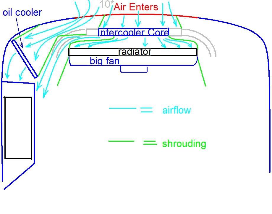
I remeber that I spend some time in 1997/8 with Super Touring cars optimizing the exit ducting of the radiator.
Please see some CFD images (ITC Calibra again) to see what a difference small changes as radiuses and the angles of the fins at
the exit can have on duct/cooling performance.
I don't think, that your car has enough front overhang to exit the air in front of the front wheels.
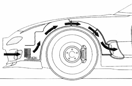
An exit behind the front wheels, would also be possible. I have included some photos and schematics to show, how it is done
on some road/race cars.
I think, that opening the floor at the side of the fuel tank, is maybe the easiest solution as far as ducting goes.
To open the inner fenders to allow the air to escape via the wheelarches is also a possibility.
This is how the cooling air escapes from most modern road cars. (see the Audi TT illustration).
To measure pressure drop across the complete radiator core, is quite intense, as far as equipment goes. I remember that we use
something like 50 pressure difference points across the radiator for race cars.
We also use some mini airs / aneometers in the ducts behind the radiator to measure air speed. This sometimes shows some quite interesting data. I have actually seen one of them ( we used 3 across the exit duct) turn backwards, due to turbulences in the duct.
Here turning vanes inside have improved the situation dramaticly.
If you have acess to some electronic data loggers, you may try to use some air mass/ratio sensors (as used by the ECU), this could be
a cheap and feasable way to measure airflow in your ducts. Maybe not in absolute terms, but it will give an indication, if it gets better or worse, why trying different solutions.
A point Neil Roshier has mentioned is maybe not entierly correct. The mesh in front of the radiator has not allways a negative effect
(sure sometimes it does). At mesh or a plate with holes in it, may help to distribute the pressure more evenly accross the core.
Neil, will see this in V8Supercars theses days. After 888 has used it for Bathurst, some years ago, nearly everybody has followed.
The main reason is to block parts of the airinlet to gain downforce/reduce drag. But before most teams used just a 50 mm high gurney
at the bottom, of the radiator. This lead to some turbulences and adverse effects for the cooling of the engine.
Now, they get the downforce increase they want with not negative effects for the cooling and can use even more blanking.
So duct design in front and after the radiator is very important. You are looking for the optimum air flow through the radiator, not just
for high pressure on one side.
As a side note, as your engine is in the rear, and the cooling lines/tubes/hoses are quite long, check for aeration in the water, as this would reduce the efficiency of the radiator as well. ( this problem is sometimes seen in dry sump installations with engine in front and oiltank in the rear of the car, as far as oil temp goes)
You could also tryto use long/fined alu tubes to run from the rear to the front, and gain some extra radiation cooling.
But this are all secondary effects at best.
some examples for cooling exits behind the front wheels.
some other possible solution:
maybe have a read here, it's worth it:
http://contrails.fre...yn_radia_en.php


TC3000
One of the baselines that I have is for my own car. It uses the same hose/tube layout, front to rear. It has a different type of radiator.

This car has a single path dual core brass radiator. The inlet opening is equivalent to the front of the radiator and the exit goes straight back and under the car. The radiator is the splitter in this case. It uses the same electric water pump and diameter lines, so I know pretty well that this combination works. I have run this car with a 110+ HP motor in 105 degree Fahrenheit ambient temperatures.
I garnered some ideas from the aircraft radiator article and also from the photos of the Audi TT. As we have the ability to form resin, curved ducts, I am tempted to make a plenum for the rear side of the radiator that then feeds up and over the fuel cell, into two large ducts that exit into the front wheel wells, forward of the tires. This assembly would have gentle curves and "guide" the air in the direction required, rather than depending on the the air finding its own direction. From the pressure distribution diagram the wheel well area would definitely be a low pressure area.
I still plan on using the small under-body splitter (air dam) so as to reduce some of the air going under the car. This will also provide some lower static pressure level the to area behind it, and to the luggage compartment in general, possible providing some small amount of aero downforce force to counteract the air going under the car.
Again, thanks everyone for the contribution of ideas.
Regard,
Paul
#27
gruntguru
-
- 7,706 posts
- Joined: January 09
Member
Posted 29 September 2009 - 05:00
Shaping the flow through the engine bay is much less important than the positions of the intake and outlet - also the shape of the air inlet in your case has a serious problem and air "guidance" in this area will make a huge difference.As we have the ability to form resin, curved ducts, I am tempted to make a plenum for the rear side of the radiator that then feeds up and over the fuel cell, into two large ducts that exit into the front wheel wells, forward of the tires. This assembly would have gentle curves and "guide" the air in the direction required, rather than depending on the the air finding its own direction. From the pressure distribution diagram the wheel well area would definitely be a low pressure area.

By gruntguru at 2009-09-28
#28
NRoshier
-
- 506 posts
- Joined: September 06
Member
Posted 29 September 2009 - 12:03
TC3000 I have some images of the blanking plates on Le Mans cars and have seen similar on CART I think - though I shudder to think how much wind tunnel work was done for each solution and the cost. BTW you have a PM.
I note with interest the change in air outlet on the GT3/4 Ferrari 430, in that the usual rad outlet is changed to a top outlet. What do you think the reasoning behind this is?
I note with interest the change in air outlet on the GT3/4 Ferrari 430, in that the usual rad outlet is changed to a top outlet. What do you think the reasoning behind this is?
#29
Joe Bosworth
-
- 687 posts
- Joined: May 05
Member
Posted 29 September 2009 - 13:28
Paul
You said above, "The formula you mentioned for "Heat transfer rate vs Velocity" would be very helpful, and gratefully accepted."
Well, here it is.
First you have to determine the energy transfer rate for the radiator standing still. The best way of determining this is by measuring the water throughput rate and water inlet and outlet temperatures and then calculating BTU per minute, or Kw or whatever units you wish to use. For purposes of below call that unity, 1.0.
Radiators transfer energy via conduction, convection and radiation. Standing still the primary factors are conduction and radiation. As you speed up air going past the fins and tubes take over.
To determine the heat transfer rate from all three transfer means with say a water temperature of 250F/120C use the following formula:
Heat transfer as compared to unity equals -0.0026 times MPH^2 plus 0.1284 times MPH plus 1.0562. That gives you a factor that you can multiply your staic velocity BTU per minute or whatever.
I can give you formulas for 200F and 300F as well as the formulas change slightly. If you want to know why I can explain but this is starting to be enough depth for now.
To make things easier, convection almost entirely takes over from about 10 MPH and things get pretty linear with:
Heat transfer factor equal to 0.0554 times MPH plus 1.524.
The problem with this latter is that it gets pretty tough calculating BTU per minute at 10 MPH for your sstarting point and the curve is exponential from 0 to 10 MPH.
I have a few insights on how radiators are designed which is quite an emperical process when I knew it. I have some of that emperical information and can add heaps more but time for bed.
Regards
#30
cheapracer
-
- 10,388 posts
- Joined: May 07
Member
Posted 29 September 2009 - 16:27
This car has a single path dual core brass radiator.
Regard,
Paul
Whats brass?
#31
Tony Matthews
-

- 17,519 posts
- Joined: September 08
Member
Posted 29 September 2009 - 16:58
Over-the-shoulder boulder holder.
#32
Tony Matthews
-
- 17,519 posts
- Joined: September 08
Member
Posted 29 September 2009 - 18:08

Reynard 97C Champcar rad outlet, two optional duct extenders in place. I think others may have been available, certainly provision was made for them if they were, as the rebate on the sidepod top edge was full-length, and threaded inserts were bonded in place.
#33
zac510
-
- 1,713 posts
- Joined: January 04
Member
Posted 29 September 2009 - 20:00
old Ferrari F430 standard configuration
<snip>
old GT3 version, with centre radiator:
<snip>
Hey TC3000, are you sure the top one is not a GT2-spec car? I am sure it is.
I asked this question many moons ago ( http://forums.autosp...showtopic=95781 ). I eventually discovered the difference is basically because of the rules and the fact that diffierent companies produced the gt2/3 versions.


