Cheers guys , that was quick

Greg - re the Mumford , I have seen various pictures , diagrams/some with dimensions of the links ,
the trouble is the two most detailed diagrams show the pivot points of the bellcrank and rocker in different geometric positions .
I don't have computer skills to work this out , I would model it full size in wood to work out what I need , just thought it might be interesting and maybe save a lot of fabrication to ask you clever chaps first

I assume the Mumford is not as simple as it appears , I think it needs careful calculation to prevent the roll centre moving about when in use [ my math is as basic as my computer skills ]
Excuse my ignorance - who is the Dixon you refer to
Bill - I have been reading your site with great interest over the past weeks [ since coming across it while researching this subject ] It really is great stuff , very interesting life you have

I think the TAM works by using the torque reaction of the axle under acceleration , against the squat loading of the chassis , to create a traction enhancing load through the tyre contact patch ?
If my research/[spying]

is correct ; viewed from the side with the car at ride height , the TAM links are : long bottom link , angled slightly up from the axle to chassis , shorter top link angled slightly down from axle to chassis ?.
As can be seen from my description , calculations are lacking !
I am basically an instinctive [ which results in lots of trial and error ] suspension modifier/builder.
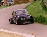
With reference to your roll centre question - The Buckler will have a low front roll centre , low roll centres seem to work for me , I am doing this as a suspension engineering exercise for my own interest and I want what I consider the ultimate live axle location/set up
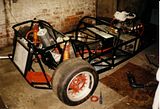
For my Buckler I am using what is a very basic [but full of lovely potential] chassis and adding/enhancing it with minimum tubing , but with 50 years of spaceframe advancement to work from .
The two options of axle links I have in mind for this car are :
1 - equal length links [20" governed by existing leaf spring mounts] , leading top link angled down slightly from chassis to axle , trailing bottom link angled up slightly from axle to chassis [both links adjustable for angle and length on axle mounting]
2 - unequal length links [20" bottom , 16-17" top, top link location and length not governed by existing chassis] bottom link angled up from axle to chassis , top link angled down from axle to chassis [as above , links adjustable on axle]
I would really like some more detailed info on the geometry / dimensions Mallock uses to make this system so effective

Bill - With reference to your Mallock 31 , do you still have the Mumford links you removed , any chance of some measurements ? maybe of the 4 link and their spacial geometry as well ?
please, pretty please

I will try and post a pic of the chassis [ taken last year by my brother , the other Buckler next to it is our 1953 MK5 Trials car]
[sorry , its defeated my IT skills , how can I post a photo thats attached to an email I received ]
Cheers
Carl
Edited by carlt, 25 July 2009 - 10:19.


