All things being equal, which type of port flows better, a tumble & dump or swirl type?
Same size inlet valve and optimised for such, etc.
I realise that generalisations can be unreliable, but I'm curious.

Tumble & dump Vs swirl ports
Started by
Bill S
, Aug 07 2009 09:28
14 replies to this topic
#3

Bill S
-
- 146 posts
- Joined: June 09
Member
Posted 07 August 2009 - 10:30
ah ...... a little. I'm more after just a simple CFM value. It doesn't need to go into any great detail as to why it works.
#4
gruntguru
-

- 7,706 posts
- Joined: January 09
Member
Posted 08 August 2009 - 05:23
All things being equal, which type of port flows better, a tumble & dump or swirl type?
Same size inlet valve and optimised for such, etc.
I realise that generalisations can be unreliable, but I'm curious.
If the swirl is being produced in the port itself, this will reduce its flow. (Sufficient swirl is often produced purely as a result of the port centreline being offset from the cylinder centreline.)
#5
J. Edlund
-

- 1,323 posts
- Joined: September 03
Member
Posted 09 August 2009 - 17:18
All things being equal, which type of port flows better, a tumble & dump or swirl type?
Same size inlet valve and optimised for such, etc.
I realise that generalisations can be unreliable, but I'm curious.
Depending on how the ports are set up they will produce some tumble or swirl naturally, but in general, when you are making a port produce more swirl or tumble you are increasing the flow resistance and decreasing the volumetric efficiency.
During the eighties it was popular to use swirl in gasoline engines, but these days it's mostly tumble that's used while diesels still use swirl. In a gasoline production engine increased levels of swirl or tumble usually decrease the cylinder to cylinder variations in the engine which is a benefit in a production engine (the engine becomes smoother and you can optimise the ignition timing better).
I think Heywood have some data of port coefficienct 'cost' for improved swirl.
#6
Bill S
-
- 146 posts
- Joined: June 09
Member
Posted 09 August 2009 - 22:49
Ta.
I've got an idea for a cylinder that won't work, I just want to prove that it won't.;)
I've got an idea for a cylinder that won't work, I just want to prove that it won't.;)
#7
Bill S
-
- 146 posts
- Joined: June 09
Member
Posted 16 August 2009 - 23:39
Here's what I wrote for another forum, I'll just copy & paste is here. Yes I know it's not 100% right but it's close enough, and this is why I started this thread.
It's often brought up how 'twin-cam heads are very big, much bigger than a rocker head', and people are correct.
But are they?
I can a think about it and when you have a look at it, the cam-on-bucket system is a bit taller than a rocker-type but not a huge amount - the different is really not so much the valve actuation but the way the head itself flows air. Multi-valve heads are usually always a tumble & dump style and those have the inlet port coming down onto the valve at as very steep angle as possible and this is what makes the head 'tall'.
If you have a look at a cross-section of a Toyota head you can see how steep that angle is ->

Some of the older heads had more horizontal ports, like an earlier version of the same engine ->

But with a tumble & dump type port, basically the steeper the port the better the airflow ..... so the good heads really are quite tall.
The other type, the swirl port, are much more compact vertically as they don't come down onto the inlet valve at much of a vertical angle, but more sideways to get the airflow to swirl around the inlet valve, like this LS7 head ->
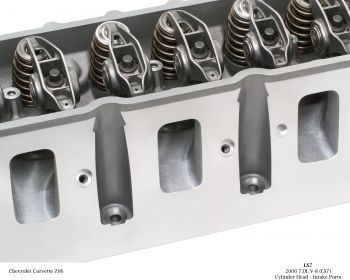
By using a swirl port is allows the head to be quite a bit shorter, and you again pick up a little bit with the more compact valve gear.
Anyway, I got to thinking and wondered if you could make a multi-valve head a full-on swirl type, to make it more compact. You'd get a lot of valve area for good breathing, a good-shaped chamber for good combustion, and the simplicity of cam-on-bucket all in a fairly compact head.
To do this, instead of siamesing the bifurcated ports from each inlet valve you'd have to spread them apart and so the inlet ports between each cylinder would be paired. So far, pretty neat. But then the cylinders at the end would have a single port for the inlet valve at the end. So for a four-cylinder head (4-pot of half a V8) you'd effectively end up with three large ports in the middle and two smaller ones at the ends .... not so neat but certainly not impossible.
I drew this rough diagram last night ->

(just drew the inlet side)
There'd be problems with interference from the inlet pulses in one cylinder affecting the neighbour one, but Chevys have lived with that for decades so that's liveable.
The side vew is pretty rough 'cause I'm crap at drawing stuff on a graphics program but you should get the idea.

(Again just drew the inlet side, and the port should be a bit shorter)
So it's looking fairly compact now and can still breath pretty well.
The problem is this though .... With the way the swirl works, it'd blow the mixture away from the spark plug and up against the cylinder wall. There'd be big problems with getting the thing to fire properly at increasing revs.
Direct injection would probably help, but I don't know enough about it.
Anyway, that's what I've been wasting a few brain CPU cycles on.
It's often brought up how 'twin-cam heads are very big, much bigger than a rocker head', and people are correct.
But are they?
I can a think about it and when you have a look at it, the cam-on-bucket system is a bit taller than a rocker-type but not a huge amount - the different is really not so much the valve actuation but the way the head itself flows air. Multi-valve heads are usually always a tumble & dump style and those have the inlet port coming down onto the valve at as very steep angle as possible and this is what makes the head 'tall'.
If you have a look at a cross-section of a Toyota head you can see how steep that angle is ->
Some of the older heads had more horizontal ports, like an earlier version of the same engine ->
But with a tumble & dump type port, basically the steeper the port the better the airflow ..... so the good heads really are quite tall.
The other type, the swirl port, are much more compact vertically as they don't come down onto the inlet valve at much of a vertical angle, but more sideways to get the airflow to swirl around the inlet valve, like this LS7 head ->
By using a swirl port is allows the head to be quite a bit shorter, and you again pick up a little bit with the more compact valve gear.
Anyway, I got to thinking and wondered if you could make a multi-valve head a full-on swirl type, to make it more compact. You'd get a lot of valve area for good breathing, a good-shaped chamber for good combustion, and the simplicity of cam-on-bucket all in a fairly compact head.
To do this, instead of siamesing the bifurcated ports from each inlet valve you'd have to spread them apart and so the inlet ports between each cylinder would be paired. So far, pretty neat. But then the cylinders at the end would have a single port for the inlet valve at the end. So for a four-cylinder head (4-pot of half a V8) you'd effectively end up with three large ports in the middle and two smaller ones at the ends .... not so neat but certainly not impossible.
I drew this rough diagram last night ->
(just drew the inlet side)
There'd be problems with interference from the inlet pulses in one cylinder affecting the neighbour one, but Chevys have lived with that for decades so that's liveable.
The side vew is pretty rough 'cause I'm crap at drawing stuff on a graphics program but you should get the idea.
(Again just drew the inlet side, and the port should be a bit shorter)
So it's looking fairly compact now and can still breath pretty well.
The problem is this though .... With the way the swirl works, it'd blow the mixture away from the spark plug and up against the cylinder wall. There'd be big problems with getting the thing to fire properly at increasing revs.
Direct injection would probably help, but I don't know enough about it.
Anyway, that's what I've been wasting a few brain CPU cycles on.
#8
gruntguru
-
- 7,706 posts
- Joined: January 09
Member
Posted 17 August 2009 - 00:52
the problem is this though .... With the way the swirl works, it'd blow the mixture away from the spark plug and up against the cylinder wall. There'd be big problems with getting the thing to fire properly at increasing revs.
The layout in your drawing won't produce swirl because one port is generating CW rotation and the other ACW. If you want swirl, just keep the ports paired as usual and angle them so the port CL misses the cylinder CL ie leave the first port the way you've drawn it and run its partner alongside it.
Don't worry about swirl centrifuging the fuel to the outside of the chamber - its not a problem.
Edited by gruntguru, 17 August 2009 - 00:54.
#9
J. Edlund
-
- 1,323 posts
- Joined: September 03
Member
Posted 17 August 2009 - 03:07
Here's what I wrote for another forum, I'll just copy & paste is here. Yes I know it's not 100% right but it's close enough, and this is why I started this thread.
It's often brought up how 'twin-cam heads are very big, much bigger than a rocker head', and people are correct.
But are they?
I can a think about it and when you have a look at it, the cam-on-bucket system is a bit taller than a rocker-type but not a huge amount - the different is really not so much the valve actuation but the way the head itself flows air. Multi-valve heads are usually always a tumble & dump style and those have the inlet port coming down onto the valve at as very steep angle as possible and this is what makes the head 'tall'.
If you have a look at a cross-section of a Toyota head you can see how steep that angle is ->
Some of the older heads had more horizontal ports, like an earlier version of the same engine ->
But with a tumble & dump type port, basically the steeper the port the better the airflow ..... so the good heads really are quite tall.
Both the heads here are designed for tumble. The first one with the higher port angle will provide better flow but less tumble, while the latter provide more tumble and less flow. For maximum power you want the design of the first head.
If you look at the picture you can actually notice that a large portion of the head is taken up by the long portion of what is essentially the intake and exhaust runner but integrated into the head. Imagine that you reduced the length of the integrated runners, lets say a vertical line from the outer sping seat surface. Then you would end up with something like this:

Suddenly you have reduced the width of the cylinder head by almost 50%.
Now, the angle of the exhaust port of much lower than that of the intake port so the exhaust cam doesn't really need to be placed as high as the intake cam. So we make the head assymetric with the exhaust cam placed slightly lower.
Finally we integrate the upper half of the camshaft bearings in the valve cover. We also shape the camshaft cover so that it closely follows the shape of the rotating camshaft. Then we have a cylinder head that is much smaller and lighter than the original Toyota head.
The other type, the swirl port, are much more compact vertically as they don't come down onto the inlet valve at much of a vertical angle, but more sideways to get the airflow to swirl around the inlet valve, like this LS7 head ->
By using a swirl port is allows the head to be quite a bit shorter, and you again pick up a little bit with the more compact valve gear.
With the LS7 head much of the shape of the ports are dictated by space required to fit the push rods. With a DOHC engine you don't have that problem.
Anyway, I got to thinking and wondered if you could make a multi-valve head a full-on swirl type, to make it more compact. You'd get a lot of valve area for good breathing, a good-shaped chamber for good combustion, and the simplicity of cam-on-bucket all in a fairly compact head.
To do this, instead of siamesing the bifurcated ports from each inlet valve you'd have to spread them apart and so the inlet ports between each cylinder would be paired. So far, pretty neat. But then the cylinders at the end would have a single port for the inlet valve at the end. So for a four-cylinder head (4-pot of half a V8) you'd effectively end up with three large ports in the middle and two smaller ones at the ends .... not so neat but certainly not impossible.
I drew this rough diagram last night ->
(just drew the inlet side)
There'd be problems with interference from the inlet pulses in one cylinder affecting the neighbour one, but Chevys have lived with that for decades so that's liveable.
The side vew is pretty rough 'cause I'm crap at drawing stuff on a graphics program but you should get the idea.
(Again just drew the inlet side, and the port should be a bit shorter)
So it's looking fairly compact now and can still breath pretty well.
The problem is this though .... With the way the swirl works, it'd blow the mixture away from the spark plug and up against the cylinder wall. There'd be big problems with getting the thing to fire properly at increasing revs.
Direct injection would probably help, but I don't know enough about it.
Anyway, that's what I've been wasting a few brain CPU cycles on.
I don't know what this is but it isn't a swirl type multivalve head. If something this type of design will prevent swirl. If you want swirl, you can move the right port to the opposite side of the head, rotate the valves around the cylinder axis by a few degrees and extended the port from the first intake valve to the second. It's hard to explain with words but take a look at this picture and I think you will understand what I mean: http://imagebank.sca...ic_e/041260.jpg
Swirl is also unsuitable for direct injection, with DI you want tumble.
#10
Bill S
-
- 146 posts
- Joined: June 09
Member
Posted 17 August 2009 - 03:29
The layout in your drawing won't produce swirl because one port is generating CW rotation and the other ACW.
It's just a stylised diagram, they're indended to be swirl-type ports.
Don't worry about swirl centrifuging the fuel to the outside of the chamber - its not a problem.
Hope that's the case - I'd like to doa CFD run on it to see what happens. As I say, I doubt it'd work but I'd like to see that.
Both the heads here are designed for tumble.
Yeah I know, that's what I wrote.
Now, the angle of the exhaust port of much lower than that of the intake port so the exhaust cam doesn't really need to be placed as high as the intake cam. So we make the head assymetric with the exhaust cam placed slightly lower.
Finally we integrate the upper half of the camshaft bearings in the valve cover. We also shape the camshaft cover so that it closely follows the shape of the rotating camshaft. Then we have a cylinder head that is much smaller and lighter than the original Toyota head.
I like that, thanks.
 Thoug not keen on having the cam cover retaining the cams, seems like it's making for hard work for yourself when working on the engine.
With the LS7 head much of the shape of the ports are dictated by space required to fit the push rods. With a DOHC engine you don't have that problem.
It's just a well-known example I used, if there's a way to make a better swirl port then since I haven't studied them much I'm like to see some thanks.
Swirl is also unsuitable for direct injection, with DI you want tumble.
Thanks again - as mentioned I don't know much about DI gear.
#11
gruntguru
-
- 7,706 posts
- Joined: January 09
Member
Posted 17 August 2009 - 04:44
It's just a stylised diagram, they're indended to be swirl-type ports.
Swirl type ports don't flow very well. You can produce swirl without the swirl type ports by simply having the port CL offset from the cylinder CL.
#12
Bill S
-
- 146 posts
- Joined: June 09
Member
Posted 17 August 2009 - 05:09
Swirl type ports don't flow very well. You can produce swirl without the swirl type ports by simply having the port CL offset from the cylinder CL.
I'm not going to agrue against that - As I said I don't think it's a good head design, it's just something I was mucking around with.
#13
carlt
-

- 4,169 posts
- Joined: June 09
Member
#14
cheapracer
-

- 10,388 posts
- Joined: May 07
Member
Posted 23 August 2009 - 11:12
I'm not going to agrue against that - As I said I don't think it's a good head design, it's just something I was mucking around with.
Heres what I think Bill.
I think you will get a good vertical twin swirl shape as both fields of flow enter and flow to the least restricted area that being the furtherest away opposite cylinder wall and then make their way down curling back up striving to go outwards naturally as there is low pressure areas ether side.
It will retain your richest part of the mixture in the center of the cylinder towards the exhaust side which should ignite well allowing you to run leaner and overall I think you may find some success with this layout.
#15
gruntguru
-
- 7,706 posts
- Joined: January 09
Member
Posted 23 August 2009 - 23:05
Heres what I think Bill.
I think you will get a good vertical twin swirl shape as both fields of flow enter and flow to the least restricted area that being the furtherest away opposite cylinder wall and then make their way down curling back up striving to go outwards naturally as there is low pressure areas ether side.
It will retain your richest part of the mixture in the center of the cylinder towards the exhaust side which should ignite well allowing you to run leaner and overall I think you may find some success with this layout.
I think that will produce minimal swirl because the shape (two semicircles in plan view) is much less conducive to swirl than a circle. Essetially the two streams will race around the perimeter and collide head-on creating more turbulence than swirl.
Edited by gruntguru, 23 August 2009 - 23:05.


