I'm familiar with Panhard rods and Watts links for laterally locating rear axles. I fabricated a Panhard rod for my MG years ago and it works great. It's long, low, level, and robust. There was plenty of room to package it, and it was simple and cheap to fabricate. Peachy.
But I'm curious about a third alternative. On the Lister Jaguar chassis, the DeDion tube is laterally located by a "sliding block". The concept is so very simple: a stout pin sticking horizontally off the back end of the rear axle (or the DeDion tube in this case) is restrained in a vertically-slotted chassis bracket. If you have a copy of Racing and Sports Car Chassis Design (Costin&Phipps), this is illustrated in Figure 49 / page 87. Clearly, the pin's location defines the rear roll center, right?
Two questions:
1) What are the disadvantages?
2) What other cars (besides Listers) have used this approach?
Lister Jaguar suspension trick
Started by
BritishV8
, Nov 03 2009 16:38
15 replies to this topic

#3

Tony Matthews
-

- 17,519 posts
- Joined: September 08
Member
Posted 03 November 2009 - 18:37
Unless I've misunderstood you, every car with a De Dion set up, I think, surely that is a fundamental part of the design.2) What other cars (besides Listers) have used this approach?
Edited to admit error! Not every De Dion set-up uses it, but I have seen it elsewhere, and now have to try to remember where!
Edited by Tony Matthews, 03 November 2009 - 19:06.
#4
SCO
-

- 36 posts
- Joined: May 03
Member
Posted 03 November 2009 - 20:41
MB GP cars in 1938-39 and BRM V16 had this arrangement.
The central section of tube also used a 'stiff' coupling that allowed relative rotation between the two ends.
The central section of tube also used a 'stiff' coupling that allowed relative rotation between the two ends.
#5
BritishV8
-
- 160 posts
- Joined: October 09
Member
Posted 03 November 2009 - 21:23
zac215: Thanks! A picture can be worth a thousand words, even when they're not quite the right ones.
Tony: No sweat. Probably other people would benefit from "seeing" alternatives anyhow, so I'll post some of my old snapshots below.
SCO: Thanks for the two leads. I want to learn more about pre-war GP cars, but I keep being outbid on eBay for used copies of the Pomeroy books.
Cool! Sounds something like what Rover used in the sixties:
ref: (article on Rover P6 design features.)
(The swivel coupling is on the left side. To locate their DeDion tube laterally, Rover angled inward the trailing links. )
Lotus used a variant of a Panhard rod on the Eleven. It connects at the driveshft tunnel close to the brake caliper:
ref: (article on a Lotus Eleven LeMans racecar.)

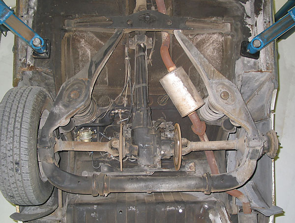
Of course if you mount the DeDion tube (or a live axle) on leaf springs, the springs provide some lateral location. It might be sufficient...
ref: (article on MG's EX186 LeMans prototype.)

Tony: No sweat. Probably other people would benefit from "seeing" alternatives anyhow, so I'll post some of my old snapshots below.
SCO: Thanks for the two leads. I want to learn more about pre-war GP cars, but I keep being outbid on eBay for used copies of the Pomeroy books.
The central section of tube also used a 'stiff' coupling that allowed relative rotation between the two ends.
Cool! Sounds something like what Rover used in the sixties:
ref: (article on Rover P6 design features.)
(The swivel coupling is on the left side. To locate their DeDion tube laterally, Rover angled inward the trailing links. )
Lotus used a variant of a Panhard rod on the Eleven. It connects at the driveshft tunnel close to the brake caliper:
ref: (article on a Lotus Eleven LeMans racecar.)
Of course if you mount the DeDion tube (or a live axle) on leaf springs, the springs provide some lateral location. It might be sufficient...
ref: (article on MG's EX186 LeMans prototype.)
Edited by BritishV8, 03 November 2009 - 21:28.
#6
Bill S
-

- 146 posts
- Joined: June 09
Member
Posted 03 November 2009 - 21:40
Not exactly on-topic, but my Fraser Clubman has a deDion rear end and it uses a lower a-arm, which is not so good for roll-steer. At least the deDion tube is straight.

#7
JtP1
-

- 753 posts
- Joined: September 08
Member
Posted 03 November 2009 - 22:43
zac215: Thanks! A picture can be worth a thousand words, even when they're not quite the right ones.
Tony: No sweat. Probably other people would benefit from "seeing" alternatives anyhow, so I'll post some of my old snapshots below.
SCO: Thanks for the two leads. I want to learn more about pre-war GP cars, but I keep being outbid on eBay for used copies of the Pomeroy books.
Cool! Sounds something like what Rover used in the sixties:
ref: (article on Rover P6 design features.)
(The swivel coupling is on the left side. To locate their DeDion tube laterally, Rover angled inward the trailing links. )
The sideways loads of the Rover system are taken by the fixed length driveshafts and fed to the centre diff. The centre link to the diff rear mount absorbs the sideways load on the mounts, without them being solidly mounted. The flanges and gaiter on the DeDion tube is a sliding joint which allows the tube to expand and contract around the fixed length driveshafts.
#8
carlt
-

- 4,169 posts
- Joined: June 09
Member
Posted 04 November 2009 - 00:34
There is a one off Lotus 6 with this exact set up , it also has a full aluminium sports car body - quite unique for the 6
disadvantages - difficult to keep lubricated / high wear rate / stiction
- roll centre not well located in the vertical
disadvantages - difficult to keep lubricated / high wear rate / stiction
- roll centre not well located in the vertical
#9
Greg Locock
-

- 6,494 posts
- Joined: March 03
Member
Posted 04 November 2009 - 23:00
disadvantages - difficult to keep lubricated / high wear rate / stiction
- roll centre not well located in the vertical
yes/yes/yes, also slop
no.
The RCH is very well defined, but remains more or less constant with respect to ground. That gives it a jounce gain of around +1, whereas normal suspensions have a RCH gain in jounce of -.7 to 0. So it is odd and the front suspension would need a bit of a rethink to match it. Or put the pin in the car and the slot on the axle. I prefer Bill's approach using a linkage, pins in slots seem a bit 1870s.
#10
Tony Matthews
-
- 17,519 posts
- Joined: September 08
Member
Posted 04 November 2009 - 23:23
As in Singer sewing machines? I still have this vision of a greased slot (pardon the expression) in back of a diff-housing, and a pin on the DD tube, but can't quite recall...I prefer Bill's approach using a linkage, pins in slots seem a bit 1870s.
#11
Bill S
-
- 146 posts
- Joined: June 09
Member
Posted 05 November 2009 - 00:19
I prefer Bill's approach using a linkage, pins in slots seem a bit 1870s.
It works, but as I mentioned it's not so good for roll-steer.
What I'd like to do is to have a conventional four-link + either a Panhard Rod (full length) or Watts Link.
One of these days if I get the time & money (this involves me winning Lotto and also fitting the Fraser with a Harltley V8) I'll make the changes to the rear end.
#12
SCO
-
- 36 posts
- Joined: May 03
Member
Posted 05 November 2009 - 09:07
As in Singer sewing machines? I still have this vision of a greased slot (pardon the expression) in back of a diff-housing, and a pin on the DD tube, but can't quite recall...
READ POST #4
#13
Tony Matthews
-
- 17,519 posts
- Joined: September 08
Member
Posted 05 November 2009 - 09:52
SORRY, MISSED IT!READ POST #4
#14
Tony Matthews
-
- 17,519 posts
- Joined: September 08
Member
Posted 05 November 2009 - 11:30

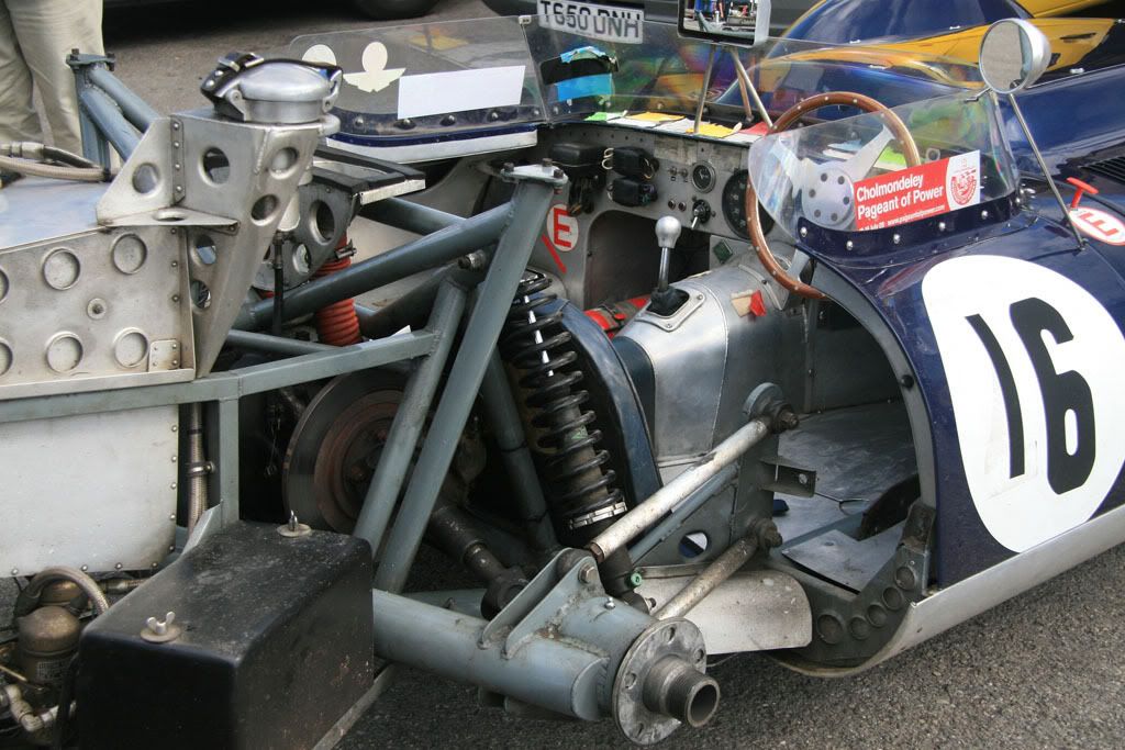
BRM V16. Copyright Tony Matthews 2009. As so much of the V16 seems to have been based on MB design, I imagine the W154 (?) was similar. Unfortunately that's another box of prints I can't find...
#15
mariner
-

- 2,401 posts
- Joined: January 07
Member
Posted 05 November 2009 - 13:53
Thsi is slightly OT but seeing the beautiful machined BRM De Dion tube above with it's grease nipple reminds me of a bit in the Coventry Climax engine book I have just seen.
The CC flat - 16 1.5 litre Gp engine never raced but it was designed as two flat - eight's back to back with a central take off to minimize torsional problems on long crank.
That required a means to assemble and dis-assemble the two peice crank. What CC used was an SKF design whereby each crank had a 1 in 50 female taper and the central drive gear had a matching 1 in 50 male taper with an interference fit when the two cranks were fully pushed onto the drive gear. An oil hole was tapped into the drive gear and to seperate the cranks you simply pumped in oil under very high pressure which forced the two cranks off. To assemble put heavy end pressure on each crank towards the centre and pump in oil to expand the tapers.
Apparently it was used on marine cranks and as far as CC could tell allowed repeated re-assembly with no heating and only a simple press jig and hand oil pump.
On the surface that seems like a useful peice of enginering, is it still used anywhere today?
#16
Tony Matthews
-
- 17,519 posts
- Joined: September 08
Member
Posted 05 November 2009 - 14:08
I bet you hoped they both popped out at the same time! It would be a bit inconvenient with one end still firmly in place...An oil hole was tapped into the drive gear and to seperate the cranks you simply pumped in oil under very high pressure which forced the two cranks off.


