Jump to content


Photo

Mass damper


  • Please log in to reply
39 replies to this topic

#1 MatsNorway

MatsNorway
  • Member

  • 2,831 posts
  • Joined: December 09

Posted 05 May 2010 - 22:18

I have been searching the forum for info about mass dampers but i could not find some easy understandable info about it.

My question was this: if i were to incorporate a mass damper in a rc car what would the spec look like.

Im thinking about turning the battery into a mass damper. at the touring cars they weigh 240-300grams out of the cars total weight of 1300grams.

Any traps to avoid?

im thinking oscillasion due to too weak springs or no damping might lead to grip, no grip, grip situasjons.

Now im unsure about the exact design of a mass damper. Is it sprung both ways or just one way. perhaps both ideas would work? the oneway idea is super easy as the potensial oscillation could be removed or reduced by stronger springs making them push the battery to top position instantly after bumps.

Must also say that rc car dampers is limited regarding bump/rebound ratio adjustments.

Edit: i just realised that it must have been one mass damper pr wheel.

lots of possibilities here.

Edited by MatsNorway, 05 May 2010 - 22:40.


Advertisement

#2 Powersteer

Powersteer
  • Member

  • 2,460 posts
  • Joined: September 00

Posted 06 May 2010 - 02:41

if its a road rc car, i cant see the use. the f1 mass damper was design for the driver to go over a curb and lose minimal grip post-curb but as far as i know rc road racers dont run the curbs because they are huge but for off-road buggies, if tuned wrongly, might go against the vehicles mass behavior and if done right, would glide over the bumps but that would be the most difficult part, tuning.

however, you can try my home made mass damper design if you dare :lol: if somehow you coul dmount the batteries where the mass is, reduce the length of the mass damper arm but a huge margin tot he drawing, it might work.
Posted Image

:cool:

Edited by Powersteer, 06 May 2010 - 02:54.


#3 DaveW

DaveW
  • Member

  • 431 posts
  • Joined: January 09

Posted 06 May 2010 - 07:01


Mass Dampers - also known as Dynamic Absorbers. An introduction to the theory may be found here. Mass dampers mounted on the sprung mass work best with no suspension springs - hence were used at the front axle of an F1 vehicle. The tuned mass is normally damped lightly to limit its travel & open up the frequency range over which it is effective. The natural frequency is important - in F1 it should have been tuned to around 7 Hz (somewhere between the heave & pitch mode natural frequencies). Good luck....


#4 Tony Matthews

Tony Matthews
  • Member

  • 17,519 posts
  • Joined: September 08

Posted 06 May 2010 - 07:30

if its a road rc car, i cant see the use.

Except that they have been used in road cars for decades.

#5 MatsNorway

MatsNorway
  • Member

  • 2,831 posts
  • Joined: December 09

Posted 06 May 2010 - 10:21


hehe thanks for the drawing. So thats how they were mounted?
it seems to be a good place to mount them. on indoor rc tracks you can kiss the curbs but you try not to because traction roll often starts with that. But my original idea was to sprung the battery so it pushes the car down on bumps making it more planted.
Like this: http://img291.images...vbatteriet.jpg/ yellow is the upper part of the chassie.

Curbs was not a part of that plan.

For more forgiving curb riding and possibly better overall ride capabilities i made this: http://img205.images...s/i/demper.jpg/

Normally rc dampers is just a piston with holes. but the one over got a valve on the underside making it faster on bumps or just in general faster on kompression depends on whats most ideal. This one is 2nd edition and will be testet on my car.


#6 Greg Locock

Greg Locock
  • Member

  • 6,492 posts
  • Joined: March 03

Posted 06 May 2010 - 11:46

List of production cars that have tuned mass dampers tuned by me

Corvette
Elan
Falcon
Piazza


I've missed a few.

#7 MatsNorway

MatsNorway
  • Member

  • 2,831 posts
  • Joined: December 09

Posted 06 May 2010 - 12:53

Good.. that means you know more than i do.

what do you think about that battery version i have linked to.

#8 Powersteer

Powersteer
  • Member

  • 2,460 posts
  • Joined: September 00

Posted 06 May 2010 - 21:43

Except that they have been used in road cars for decades.

I had the impression that RC racing is done on ultrasmooth surfaces unlike roadcars. Greg, we can't simply build one and make it work can we? does it simply require a nice rebound set up if it were to be like Renaults (vertical, physically direct against motion)? Matts, the drawing I did was just playing about, whether it could work I don't know but so far I have not seen one made that way although the J-Damper is a lightweight version of that.

:cool:


#9 DaveW

DaveW
  • Member

  • 431 posts
  • Joined: January 09

Posted 07 May 2010 - 08:09

...I have not seen one made that way although the J-Damper is a lightweight version of that.


Apologies, Powersteer, but your sketch does not represent a "J-Damper" (inerter). An inerter does not contain springs, & neither does it dissipate energy (not intentionally, anyway). It simply generates a force, proportional to its effective mass, to oppose any relative acceleration of its two end fittings. Hence, if DDX1 & DDX2 are the absolute accelerations of the two end fittings, respectively, then Inerter_Force = Inerter_Mass*(DDX1 - DDX2). Choose a sign convention to make sure the force resists the relative acceleration. The device is very simple in concept, but is not so simple to implement reliably. Its effect on suspension performance is complex.


#10 MatsNorway

MatsNorway
  • Member

  • 2,831 posts
  • Joined: December 09

Posted 07 May 2010 - 09:46

I had the impression that RC racing is done on ultrasmooth surfaces unlike roadcars


Yes and no. Some carpet tracks are really smooth, but some got more bumps than the tarmac tracks because the carpet curls as it gets streched. And on the outdoor race tracks you can hear the nitro engines go up and down in rpm at the straights because they are skipping along the bumps. you can also se it on the track as the dark racing line gets sebra stripes at every little bump and ditch.

The track im going racing this summer, with a electric touring car.
http://www.youtube.c...feature=related
at 3.48 and out you can hear it, and see it in the long corner.

Edited by MatsNorway, 07 May 2010 - 09:58.


#11 Greg Locock

Greg Locock
  • Member

  • 6,492 posts
  • Joined: March 03

Posted 07 May 2010 - 23:55

Hang on, inerters and tuned mass dampers and just plain old mass are three different things. There's a good article on inerters somewhere, never seen one, sound fascinating. TMDs aka harmonic dampers are probably what Renault was using that got banned (the maths is the same whether you are talking about crankshafts or car bodies). I doubt anyone adds mass to a racing car once it is at the legal minimum, tho BMW and Porsche have done to their road cars.

I think there could be some mileage in tuning a TMD to wheelhop - ideally on the unsprung mass, but there could be a benefit even on the sprung side. Unfortunately it is a case of suck it and see, unless you know a great deal about the car and the properties of the damper. The original 2cv used a TMD instead of a normal shock on its rear suspension. In effect they just unbolted the top of the shock from the body, turned it into a coil over, and added a small mass to react the shock forces. Result is that wheel motion is damped but the forces generated by doing so are not reacted into the body.


#12 Grumbles

Grumbles
  • Member

  • 326 posts
  • Joined: September 09

Posted 08 May 2010 - 07:12

Greg, I'm having a hard time understanding how the inerter helps with wheel control. To my admittedly unsophisticated mind it looks as if it would have an effect similar to increasing the unsprung mass. What am I missing?

#13 SteveCanyon

SteveCanyon
  • Member

  • 245 posts
  • Joined: December 09

Posted 08 May 2010 - 10:12

Greg, I'm having a hard time understanding how the inerter helps with wheel control. To my admittedly unsophisticated mind it looks as if it would have an effect similar to increasing the unsprung mass. What am I missing?


.... um same here I have to admit. :(
The best I can figure is much the same; it makes the unsprung mass 'seem' greater .... ?

#14 DaveW

DaveW
  • Member

  • 431 posts
  • Joined: January 09

Posted 08 May 2010 - 10:13

Hang on, inerters and tuned mass dampers and just plain old mass are three different things.


True.

Back to Mat's question for a moment. If his vehicle is adequately suspended, then the best way to improve ride &, potentially, CPL control is to bolt mass to the sprung mass, but that is not very efficient because the additional mass has to be accelerated (& decelerated). The efficiency can be improved (again potentially) if a reduced mass is suspended from the sprung mass. Then the effective added mass is enhanced (increased dynamically), but only over a restricted frequency range. As the damping of the added mass suspension is reduced, the effective additional mass is increased, but over an ever narrower band of frequencies. At the (theoretical) limit, the effective added mass tends to infinity, but only at one specific frequency. That is a dynamic absorber. All that remains is to choose where & how to attach the added mass & to select the frequency at which it is to be effective. The acceleration of the added mass itself will be much greater than the acceleration of the mounting point at its working frequency (& inversely proportional to the value of the added mass).

Leaving aside the fact that, in my experience, batteries tend to be sensitive to acceleration, attaching a dynamic absorber to the sprung mass is of limited value (and may even be a disadvantage) when the vehicle is adequately suspended. The device can become useful if/when the vehicle is not adequately suspended (e.g. the front axle of an F1 vehicle). Hence my original comment that they work best when the normal suspension springs are removed.

An interesting aside to the above (perhaps), is the fact that the sprung mass of a race vehicle is not a monolith (a common assumption), but comprises a large number of assemblies that are connected together by stiff (but not infinitely stiff) structure. Hence the effective sprung mass is greater than static at the frequency of the heave mode. Surprisingly, perhaps, the effect is not negligible. If the modal response of, for example, a GP2 vehicle is to be predicted accurately, the effective sprung mass must be increased by roughly half the mass of the unsprung elements. That curiosity caused me much soul-searching when I was developing inertial parameter identification procedures.

Some of the effects of adding an inerter to an existing suspension:

- suspension spring rate is reduced dynamically
- dampers are "linearized" dynamically
- bump rubbers "disappear" dynamically
- the hub mode natural frequency & damping ratio is reduced (similar to an increased hub mass, but without the mass)
- an additional high frequency "hub mode" is introduced.

In summary, inerters can help to mitigate the dynamic effects of some of the "nasties" used to manage aero characteristics & can also be used to manipulate the rate of heat input to (slick) tyres. They are not "bolt on speed".

Edited by DaveW, 08 May 2010 - 13:39.


#15 MatsNorway

MatsNorway
  • Member

  • 2,831 posts
  • Joined: December 09

Posted 08 May 2010 - 11:25

This is getting a bit tricky for my limited english skills.

Bump rubber?

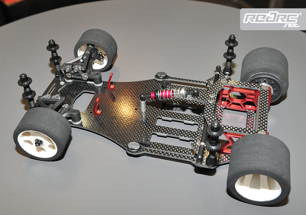
The car i was thinking would do good with a mass damper in the front does not have dampers they just have a hub that slides on a shaft with a spring under it to absorb bumps.

Posted Image

1/12 track they are called.

This type:Posted Image

Its a simple looking thing but it is the fastest rc car class you can race.

The car runs foam tires and that "rubber" is being worn down until the glue lets go and there is only rim left. the tires usually gets mounted in a lathe and trued down to equal size before race.


then you have the more advanced and more powerfull touring cars. they have fully independent suspension, stabilisers, 4WD, twise the volts and top speeds at 90-100km/t on outdoor tracks. And they got all the adjustment possibilities you can think of. try me.

Posted Image

they usually run rubber tires but in US they run foam too.

So know we got that cleared.

I was thinking mass damper in the front suspension on the track car. and a simpler version of the mass damper with the battery. Most likely its a big no no to lift the battery since these cars need to have as low CG as physically possible.

so its probably only a good idea on the front suspension.

track car minimum weight is 730grams+- . touring is is 1300+grams. the touring car on rubber has logged 4Gs at max on tarmac. (probably under braking he did not remember) when it comes to weight the cars usually has some lead added either to get it legal or to fine tune the balance.

The cars relies heavily on aero and mostly you remove flap on the track cars to get rid of understeer on power.

Edited by MatsNorway, 08 May 2010 - 11:27.


#16 DaveW

DaveW
  • Member

  • 431 posts
  • Joined: January 09

Posted 08 May 2010 - 12:09

Bump rubber?


See, for example, this. (SMAC is not the only supplier of such stroke-limiting/spring supporting products).

Your rc models are impressively elegant. I doubt that Ayrton Senna would have bothered with F1 if he had had some those to exercise his skills with.

The touring car appears to have all the tools required to achieve a competent mechanical set-up. Personally, I would not consider a mass damper for that version (but then, I wouldn't consider attempting a scaled damper either....).

I admit that I can't decide on the kinematics of the "track" version. It looks as though the rear axle (along with rear structure) is "live", controlled by a single coil-over damper? The front axle appears to be independent, but with no obvious springs or dampers? I'd be interested to understand the kinematics better....


#17 MatsNorway

MatsNorway
  • Member

  • 2,831 posts
  • Joined: December 09

Posted 08 May 2010 - 14:46

Your rc models are impressively elegant. I doubt that Ayrton Senna would have bothered with F1 if he had had some those to exercise his skills with.


sadly none of them are mine. :(

The touring car appears to have all the tools required to achieve a competent mechanical set-up. Personally, I would not consider a mass damper for that version (but then, I wouldn't consider attempting a scaled damper either....).


They surtenly have allot of setup possibilities. ackermann, camber lift, bump steer. you name it.

The track car is the one in my view that has the most improvement potensial. the reason for that is that it does not have much of adjustment posibilites at the rear, so to counter a few of those limitasjons i want to generate new things to it.

I have been lucky engough to meet a guy on the racetrack that has allready been building hes own track car, i have allready started to design him a new rear pod with a intergrated diffuser.


I admit that I can't decide on the kinematics of the "track" version. It looks as though the rear axle (along with rear structure) is "live", controlled by a single coil-over damper? The front axle appears to be independent, but with no obvious springs or dampers? I'd be interested to understand the kinematics better....


The single damper and spring controll only bump not roll. there is one tiny spring on each side that can be replaced or possibly adjusted to adjust the ease of roll. there is no damping from side to side.

Picture of springs on the car that is to get a diffuser:Posted Image
That car also got whats called a T-bar. A T-bar was more common before the link system. Alf the guy i design the diffuser rear for has both since he claims to feel a difference. I suspect the T-bar got some damper qualities.

Better picture of the rear suspension: Posted Image

the front hubs got wishbone like arms holding it but the spring is located directly on the hub. you can see it if you look closely on the first picture (prev post).

Alf is trying to make a damper into the hub, problem is that there is no champer the oil can go to at bump. (stroke?) so i don`t think it will work until he gets that.

http://www.rctech.ne...t-star12-6.html


#18 MatsNorway

MatsNorway
  • Member

  • 2,831 posts
  • Joined: December 09

Posted 08 May 2010 - 14:57

Another idea i have is to build complete new rear axle mounting. Because of the way the suspension is layd out it moves up and down alot during acceleration or braking. fairly normal but problem is that these are sensitive to aerodynamics.

So according to a pro he could feel the difference between a car that got holes in the front of the chassie and one that has not. to adress this (and possibly improve diffuser work enviroment) i want to suggest to him a different type of link system. where you could adjust the anti squat by chancing the arms attachment points. my idea would also incorporate one damper per side.

But main problem is allways weight.

730grams is not much, motor alone weights 170grams today. Ive given him this link and suggested a lighter (150grams) and more powerful motor.

http://forum.radiost...otor-registeret

Edited by MatsNorway, 08 May 2010 - 14:58.


#19 Powersteer

Powersteer
  • Member

  • 2,460 posts
  • Joined: September 00

Posted 09 May 2010 - 04:43

Apologies, Powersteer, but your sketch does not represent a "J-Damper" (inerter). An inerter does not contain springs, & neither does it dissipate energy (not intentionally, anyway).

My sketch is just playing but the character could be similar to a J-Damper's. Don't the J-Dampers share springs with the suspensions? The interesting thing about the drawing I made up was that, on a lean angle, the mass could actually made to move to the inner center of the vehicle.

:cool:

Edited by Powersteer, 10 May 2010 - 03:50.


Advertisement

#20 gruntguru

gruntguru
  • Member

  • 7,705 posts
  • Joined: January 09

Posted 10 May 2010 - 02:35

on a lean angle, the mass could actually made to move to the inner center of the vehicle.


Cornerig force applied to the mass would also resist roll.

#21 Powersteer

Powersteer
  • Member

  • 2,460 posts
  • Joined: September 00

Posted 10 May 2010 - 03:18

Ok Mats, rc mass damper D.I.Y using the speed controller as mass hanging over the front of the car in this case. Other location is possible but the easiest to draw was this configuration  ;) Will it work? Or can you make it work. Probably instead of rubber band maybe torsion springs (coil type).

Posted Image

Found this to be a good read, even on the comments. Mass Damper AtlasF1 classic

:cool:

Edited by Powersteer, 10 May 2010 - 06:07.


#22 MatsNorway

MatsNorway
  • Member

  • 2,831 posts
  • Joined: December 09

Posted 10 May 2010 - 08:41

Ok Mats, rc mass damper D.I.Y using the speed controller as mass hanging over the front of the car in this case. Other location is possible but the easiest to draw was this configuration ;) Will it work? Or can you make it work. Probably instead of rubber band maybe torsion springs (coil type).

Posted Image

Found this to be a good read, even on the comments. Mass Damper AtlasF1 classic

:cool:


haha, well.. it might work but the 12 scale got only 3mm ground clearance. The touring cars got 5mm minimum.

I read the link. And im not sure i understood it. The j-damper does reduce oscillation in the suspension?

from before i imagined it would delay dive under braking if mounted in the front is that right?

Does it get used in Le mans cars and sports cars? if not that must be because they don`t have a balloon wheel to cope with.

Edit: here is one of my mass damper ideas(minus some slight damping) http://img203.images...amperfront.jpg/

Edited by MatsNorway, 10 May 2010 - 09:31.


#23 DaveW

DaveW
  • Member

  • 431 posts
  • Joined: January 09

Posted 10 May 2010 - 15:34

First, I would like to separate the concepts of Mass damper & J-damper (inerter). They are quite different. I confused things by trying to answer Grumbles question & yours in the same post, for which I apologize.

I don't think an inerter would be applicable to a scale model, because it works by modifying the response of an existing suspension (normally, in its simplest form, it adds a device in parallel with an existing spring & damper).

On the other hand, it is (just) possible that a Mass damper might help in your application. My thought is to add a mass on the vehicle centreline as far forward as possible & attached to the platform supporting the front suspension by a cantilevered single leaf spring. The natural frequency of the mass & leaf spring should be set at around ten percent higher than the natural frequency of the vehicle on its tyres (hence you need to measure/estimate this before starting serious work), and could be made adjustable by changing the effective length of the leaf spring. Ideally, the deflection of the mass should be limited by end stops. If I have interpreted your photos correctly, you might try removing the existing front springs. The value of the added mass? Perhaps 10 percent of the platform. Here is a rough sketch.

I am concerned that a) the foam tyres may already have sufficient intrinsic damping not to require a Mass damper (unlike F1's "balloon" tyres) & b) the device won't "scale" well (will be too large &/or delicate for your application).

Edited by DaveW, 10 May 2010 - 15:58.


#24 Powersteer

Powersteer
  • Member

  • 2,460 posts
  • Joined: September 00

Posted 10 May 2010 - 18:48

This is getting interesting. Inerters are way too complicated to tune anyway, I'm not even too sure what all their benefits are having no experience with them, should have never mentioned them in my earlier post, apology is on me. Anyway, your drawing is like another idea which had spring joints or flexible spring joints. What about controlling the mass? I saw an R/C site that has a Mass Damper that just have a spring and mass, like your illustration so is it just a matter of controlling the spring rate to the right tune? No damper mechanism? It seems your idea of a mass Damper is pretty advance in that, it is more about controlling the tyre contact patch or getting a more linear grip in the constantly vibrating scenario of a wheel regardless of bump beyond the primary suspension rather than the basics of controlling the motion of the vehicle only when it is disturbed a.k.a much more towards controlling wheel frequency where the first suspension can't rather than merely minimizing the effect of curb bounce or bounce in general?

So tuning it would merely be trial and error I suppose. I'm curious, does an R/V car bounce about a lot?

Posted ImagePosted Image

:cool:

#25 DaveW

DaveW
  • Member

  • 431 posts
  • Joined: January 09

Posted 10 May 2010 - 20:11

In theory, assuming components don't wear out or fatigue and provided the input is continuous, it is unnecessary to dissipate energy from Mass dampers (dynamic absorbers). In fact, they will work most efficiently without damping - for a single frequency excitation. Dynamic absorbers very similar to the one I sketched were used, for example, on DC9 aircraft engine bearers to isolate an engine mode from the passenger cabin in the cruise condition.

In reality, however, inputs are rarely continuous or single frequency, & components will wear out &/or fatigue. Hence the DC9 units had to be replaced (I recall) every 60 hours or so before fatigue destroyed the absorber springs.

As Greg has indicated, dynamic absorbers have also been used to isolate the passenger cells of road vehicle from various "shake" problems, usually caused by engine/power train modes that are lightly damped. So far as I am aware, these are rarely damped explicitly, although the materials (polymers) used to suspend the masses usually have intrinsic damping properties. It is also worth noting that it is almost impossible to construct anything mechanical that is totally devoid of damping.

Damping becomes more important when the vibration to be tamed is more broad-band, & is not continuous. Renault's mass damper would be an example. Even in this case, however, damping is likely to be relatively modest (one F1 example used air leakage across the contained mass for damping). A more "advanced" version of the sketch I drew for Matt might, for example, use two parallel spring elements separated by an elastomer "filler" to provide the damping.

It is important to remember, however, is that a Mass damper will work efficiently only when its natural frequency is "tuned" appropriately to the vehicle or sub-assembly to which it is attached. Hence, in principle at least, Renault would have tuned the mass damper for hot, rather than cold, tyres. It is also worth noting again that, for this application, the purpose is to control contact patch load variations, rather than sprung mass disturbances. A mass damper will do little to improve contact patch load control if it is attached to a sprung mass that is itself suspended properly. Hence it is, ultimately, a "fix".


#26 Greg Locock

Greg Locock
  • Member

  • 6,492 posts
  • Joined: March 03

Posted 11 May 2010 - 00:25

Absolutely TMDs generally work best when damping is small. It is all too easy to lock the secondary mass to the primary with friciton and damping. Typical soft rubbers have a damping of about the right proportion, but once you get to Shure 80 or so they tend to overdamp.

If you are interested in them the a simple 2 degree of freedom spring mass model willl teach you far more about the interplay between the two systems than any post. Fairly easy to do in Excel, easy in matlab or mathcad, bit of a bugger to understand the implications of the results if you derive it by hand. It's a standard case I'm sure all vibration books cover it.


#27 MatsNorway

MatsNorway
  • Member

  • 2,831 posts
  • Joined: December 09

Posted 11 May 2010 - 12:28

If you are interested in them the a simple 2 degree of freedom spring mass model willl teach you far more about the interplay between the two systems than any post. Fairly easy to do in Excel, easy in matlab or mathcad, bit of a bugger to understand the implications of the results if you derive it by hand. It's a standard case I'm sure all vibration books cover it.


Well i can have a look at it.

btw i think this: http://img203.images...amperfront.jpg/ should be chanced so the joint and the mass chances places. I think the upward motion of the mass on bumb would affect the chassie negatively.

Edited by MatsNorway, 11 May 2010 - 12:35.


#28 Twin

Twin
  • New Member

  • 13 posts
  • Joined: March 10

Posted 11 May 2010 - 19:13

Something you might like
:)

Posted Image

Edited by Twin, 11 May 2010 - 19:14.


#29 MatsNorway

MatsNorway
  • Member

  • 2,831 posts
  • Joined: December 09

Posted 11 May 2010 - 19:25

I have seen it. :)


ohh btw there is F1 rc racing with balloon tires too.

Posted Image

Posted Image

Edited by MatsNorway, 11 May 2010 - 19:39.


#30 MatsNorway

MatsNorway
  • Member

  • 2,831 posts
  • Joined: December 09

Posted 02 July 2010 - 12:01

Doesn`t it look like this one has a J-damper or least a damper in the middle there?
Posted Image

Edit: just found this: Posted Image

#31 Powersteer

Powersteer
  • Member

  • 2,460 posts
  • Joined: September 00

Posted 03 July 2010 - 07:52

Would it be safe to say to use time as a measurement to tune the mass damper correctly? I mean, if i were press a car down to a given state and if it returns in say 1 sec then press the floating secondary mass to an equivalent state and it returns also in a 1 sec...this should be a nice set up wouldn't it? sorry but i'm doing DIY mentality here. If the spring rates ratios are matched for both primary and secondary mass, would it be sufficent to ge an adjustable damper on the secondary damper to tune it to match the primary damper this way? By the way, nice attachment TC3000, played with it for some time.

:cool:

#32 Greg Locock

Greg Locock
  • Member

  • 6,492 posts
  • Joined: March 03

Posted 04 July 2010 - 04:11

A mass damper oscillates rather than just a half cycle, but yes the idea is sound.

Given the ubiquity of PC soundcards there is no reason not to analyse it properly.


#33 gruntguru

gruntguru
  • Member

  • 7,705 posts
  • Joined: January 09

Posted 04 July 2010 - 07:10

By the way, nice attachment TC3000, played with it for some time.


Did the model make sense to you? I found that as soon as you set either "zeta" to even slightly overdamped (>1) the system will not oscillate - even with the other zeta set near zero (the system should work as a 1 DOF in this situation). Changing the overdamped zeta to just below critical suddenly allows the whole system to oscillate.

#34 MatsNorway

MatsNorway
  • Member

  • 2,831 posts
  • Joined: December 09

Posted 07 July 2010 - 18:05

Here is a video from the World championship. The car i posted above is in action with a driver named Naoto. Hes on Pole.
http://www.youtube.c...player_embedded

Since technology makes the F1 cars lighter and stronger on a regular basis and since FIA has stated that next year the weight limit will be 640? kg dry.

I was wondering if it would be a possibility to see a team try to unload their motors from being a part of the chassis and instead have a slightly damped motor for.. less internal stress perhaps? or perhaps to get a mass damper like property from the engine. After all, its no rule that states that the motor mounts must be solid steel or something like that?

If you limit the movement to only the vertical plane it should work right?

#35 Greg Locock

Greg Locock
  • Member

  • 6,492 posts
  • Joined: March 03

Posted 07 July 2010 - 23:14

I was wondering if it would be a possibility to see a team try to unload their motors from being a part of the chassis and instead have a slightly damped motor for.. less internal stress perhaps? or perhaps to get a mass damper like property from the engine. After all, its no rule that states that the motor mounts must be solid steel or something like that?

If you limit the movement to only the vertical plane it should work right?

On production cars that is already done, and has been since at least 1984 (first time I tuned engine mounts to improve secondary ride). Some manufacturers still don't do it right. Even if their name is the only one that blondes can spell.

#36 MatsNorway

MatsNorway
  • Member

  • 2,831 posts
  • Joined: December 09

Posted 08 July 2010 - 14:46

On production cars that is already done, and has been since at least 1984 (first time I tuned engine mounts to improve secondary ride). Some manufacturers still don't do it right. Even if their name is the only one that blondes can spell.


I know. The Nissan GTR even has some new tech in that area making the engine lean on the suspension somehow. And Porsche got those fancy hydraulic motor mounts to stiffen up the motor under load etc.

is it feasible to see a F1 car with that sort of solution? Does anyone know how much ballast some of the F1 cars carries/ or has carried as extra?

#37 gruntguru

gruntguru
  • Member

  • 7,705 posts
  • Joined: January 09

Posted 09 July 2010 - 00:58

is it feasible to see a F1 car with that sort of solution? Does anyone know how much ballast some of the F1 cars carries/ or has carried as extra?


That has already been ruled on. As soon as a team adds springs to a piece of ballast it becomes a TMD and they are banned.

#38 MatsNorway

MatsNorway
  • Member

  • 2,831 posts
  • Joined: December 09

Posted 09 July 2010 - 06:39

That has already been ruled on. As soon as a team adds springs to a piece of ballast it becomes a TMD and they are banned.


the Definition of ballast might make it possible to do so with the engine.

In my eyes the engine is not ballast.

Edited by MatsNorway, 09 July 2010 - 06:39.


#39 gruntguru

gruntguru
  • Member

  • 7,705 posts
  • Joined: January 09

Posted 09 July 2010 - 08:17

the Definition of ballast might make it possible to do so with the engine.
In my eyes the engine is not ballast.


I agree. I was responding to your reference to ballast.

Advertisement

#40 MatsNorway

MatsNorway
  • Member

  • 2,831 posts
  • Joined: December 09

Posted 09 July 2010 - 09:10

I agree. I was responding to your reference to ballast.


Sorry, i should have said that i was curious about the ballast because of the extra material needed in the chassis, so it can carry the engine.