Today I got the FEA analysis back for the chassis design I have been working on. This is a Porsche 911 sized mid engined space frame car. Bare chassis was reported as being 24,000Nm/deg bare and 40,000Nm/deg with alloy honeycomb panels installed. The engineer who did the FEA does this sort of work for a living, but assuming some error and some poor detail in the construction accounting for 20% of the figure I am still well above the 6,000Nm/deg required by the regulations. But how much is enough? 6,000Nm/deg hardly seems like a stiff enough chassis.

Minimum torsional stiffness?
Started by
NeilR
, Feb 01 2011 09:32
47 replies to this topic
Advertisement
#2

Paolo
-

- 1,677 posts
- Joined: May 00
Member
Posted 01 February 2011 - 10:05
Today I got the FEA analysis back for the chassis design I have been working on. This is a Porsche 911 sized mid engined space frame car. Bare chassis was reported as being 24,000Nm/deg bare and 40,000Nm/deg with alloy honeycomb panels installed. The engineer who did the FEA does this sort of work for a living, but assuming some error and some poor detail in the construction accounting for 20% of the figure I am still well above the 6,000Nm/deg required by the regulations. But how much is enough? 6,000Nm/deg hardly seems like a stiff enough chassis.
What springs-bars do you plan to use, and what suspension?
You could try modeling the front and rear suspension systems as two torsion springs. Chassis stiffness is a third spring connecting them.
If chassis stiffness is 20 times stiffer than the stiffer of the suspensions, you are probably in a decent region. Then add stiffness if you don't have a weight penalty.
See Greg's and other's words of wisdom here:
http://forums.autosp...showtopic=98078
Edited by Paolo, 01 February 2011 - 10:09.
#3
NeilR
-
- 623 posts
- Joined: October 09
Member
Posted 01 February 2011 - 11:13
How could I forget that!
I'm comfortable with what my figures will be, even if they are optimistic given the potential losses I might build in during construction. I have been told since posting the above that the 6,000Nm/deg figure is to allow Cobra Replica's to be registered.
I'm comfortable with what my figures will be, even if they are optimistic given the potential losses I might build in during construction. I have been told since posting the above that the 6,000Nm/deg figure is to allow Cobra Replica's to be registered.
Edited by NeilR, 01 February 2011 - 11:14.
#4
Paolo
-
- 1,677 posts
- Joined: May 00
Member
Posted 01 February 2011 - 11:50
How could I forget that!
I'm comfortable with what my figures will be, even if they are optimistic given the potential losses I might build in during construction. I have been told since posting the above that the 6,000Nm/deg figure is to allow Cobra Replica's to be registered.
Do they build Cobra replicas out of cardboard?
Edited by Paolo, 01 February 2011 - 17:11.
#5
Bloggsworth
-

- 9,509 posts
- Joined: April 07
Member
Posted 01 February 2011 - 17:48
Do they build Cobra replicas out of cardboard?
I seem to recall that 6,000 lbs/ft (or ft/lbs I can never remember which way round) or less was about what Lotus 18s and cars of that ilk were achieving, and I suspect that Lotus 11s and Mk1 Lolas were a bit less, but as cars ran softer suspensions and had bigger ride heights, this was no problem. Of course, having a roof makes a lot of difference.
#6
Johan Lekas
-

- 52 posts
- Joined: May 09
Member
Posted 01 February 2011 - 20:17
From Tony Rudd's Design Internal Memo 1976:
"Measured over the wheelbase, one axle restrained and lifting one corner of the opposite axle, torsional stiffness of the entire structure must exceed 2,500ft.lbs (3456Nm) per degree. The variation in stiffness per foot of wheelbase must not exceed +/- 10% or 15% between two adjacent sections otherwise fatigue failures are likely."
(Memo can be found here http://www.formulast...rner-for-2010/)
#7
Bloggsworth
-
- 9,509 posts
- Joined: April 07
Member
Posted 01 February 2011 - 21:04
From Tony Rudd's Design Internal Memo 1976:
"Measured over the wheelbase, one axle restrained and lifting one corner of the opposite axle, torsional stiffness of the entire structure must exceed 2,500ft.lbs (3456Nm) per degree. The variation in stiffness per foot of wheelbase must not exceed +/- 10% or 15% between two adjacent sections otherwise fatigue failures are likely."
(Memo can be found here http://www.formulast...rner-for-2010/)
Was that for a monocoque or space-frame? No wonder the 12,000 ft/lbs of the Austin 1800 caused such a stir!
Edited by Bloggsworth, 01 February 2011 - 21:08.
#8
gruntguru
-

- 7,706 posts
- Joined: January 09
Member
Posted 02 February 2011 - 00:17
One point often glossed over (although covered by any reference to chassis resonant frequencies) is the relevence of vehicle mass. Even more important is the distribution of mass along the x axis and more important still, the distribution of rotational inertia (Ixx) along the x axis. This will dictate the torsional mode spectrum (along with the distributed torsional stiffness along the x axis).
Back to the subject of mass. It is not surprising to see torsional stiffness values for F1 that are substantialy lower than say the Bugatti Veyron. The Veyron is after all three times the mass of the F1 car, has probably greater than 4 times the Ixx and would certainly have a less favourable distribution of mass and Ixx than the F1.
Back to the subject of mass. It is not surprising to see torsional stiffness values for F1 that are substantialy lower than say the Bugatti Veyron. The Veyron is after all three times the mass of the F1 car, has probably greater than 4 times the Ixx and would certainly have a less favourable distribution of mass and Ixx than the F1.
#9
kikiturbo2
-

- 879 posts
- Joined: December 04
Member
Posted 02 February 2011 - 01:08
hehe, been involved in just such discussion about the new pagani vs. veyron..  people often forget that when you have a car that is half the weight, it really doesn't have to have the same torsionall stiffness..
people often forget that when you have a car that is half the weight, it really doesn't have to have the same torsionall stiffness..
#10
Bloggsworth
-
- 9,509 posts
- Joined: April 07
Member
Posted 02 February 2011 - 09:51
It does if it pulls 3 to 4 times the G forces and rides on cart springs.
#11
NeilR
-
- 623 posts
- Joined: October 09
Member
Posted 02 February 2011 - 11:24
mass of my car will be 950kg.
#12
mariner
-

- 2,401 posts
- Joined: January 07
Member
Posted 02 February 2011 - 13:56
Building on GruntGuru's comment above on mass distribution another factor in Torsional stiffness is wheelbase ( or strictly spring base).
You can't really compare torsional stiffness test results or how much you "need" wihout considering the distance between the spring centres. So as F1 wheelbases have grown for aero reasons more effort is required to acheive the same end to end number.
The other thing is that the stiffness is in two parts engine/geasrbox and rest of chassis. Say about 1/3 rd ( roughly) of an F1 chassis torsional stiffness is engine/transmission not actual chassis.
#13
Magoo
-

- 3,856 posts
- Joined: October 10
Member
Posted 02 February 2011 - 13:57
Do they build Cobra replicas out of cardboard?
I don't know, but the originals were apparently fabricated from reclaimed downspout. When you see one disassembled, it's sort of breathtaking.
#14
Kelpiecross
-

- 1,730 posts
- Joined: October 10
Member
Posted 03 February 2011 - 02:35
mass of my car will be 950kg.
NeilR - it is none of my business but you really do need to stop obsessing about details and just get on with welding, bolting etc. your car together. Designing and building your own car is a huge enough job without making it harder for yourself. Nobody can plan every last tiny detail in advance. The fibreglass body alone will take at least five years to build - if you are lucky.
Just build this car - worry about the details on the Mark 2 version.
Edited by Kelpiecross, 03 February 2011 - 02:36.
#15
Catalina Park
-

- 6,891 posts
- Joined: July 01
Member
Posted 03 February 2011 - 06:53
I saw an original one hanging on a wall in a shed at Torrance Airport in 1991.I don't know, but the originals were apparently fabricated from reclaimed downspout. When you see one disassembled, it's sort of breathtaking.
#16
Magoo
-
- 3,856 posts
- Joined: October 10
Member
Posted 03 February 2011 - 06:55
I saw an original one hanging on a wall in a shed at Torrance Airport in 1991.
On a nail, I suppose.
#17
Catalina Park
-
- 6,891 posts
- Joined: July 01
Member
Posted 03 February 2011 - 07:45
The story I got was it had been over a cliff.On a nail, I suppose.
#18
DaveW
-

- 431 posts
- Joined: January 09
Member
Posted 03 February 2011 - 22:42
Today I got the FEA analysis back for the chassis design I have been working on. This is a Porsche 911 sized mid engined space frame car. Bare chassis was reported as being 24,000Nm/deg bare and 40,000Nm/deg with alloy honeycomb panels installed. The engineer who did the FEA does this sort of work for a living, but assuming some error and some poor detail in the construction accounting for 20% of the figure I am still well above the 6,000Nm/deg required by the regulations. But how much is enough? 6,000Nm/deg hardly seems like a stiff enough chassis.
Measured free-free torsional stiffness for a (large & heavy) fully furnished racing tin top with structural roll-over cage was around 30KN.m/deg.
For a second level open wheeler, measured free-free chassis torsional stiffness was around 16KN.m/deg, or 7.5KN.m/deg upright/upright.
Personally, I wouldn't bother with honeycomb panels if you are happy with your FEA estimates.
#19
NeilR
-
- 623 posts
- Joined: October 09
Member
Posted 04 February 2011 - 00:09
Thanks for your information Dave. I have been considering not using the hc panels, but I need panelling and flooring of some sort and having recently driven a car with plain alloy panels I'm not sure I could put up with the lack of refinement...though I'm sure there is a solution. The HC panel floor and bulkheads will have to stay as the floor and rear 'tank' bulkhead will make up a significant element of the seating to allow official road use. I'll discuss it with Brett at Bremarauto as he is doing the FEA.
Edited by NeilR, 04 February 2011 - 00:11.
Advertisement
#20
RDV
-

- 6,765 posts
- Joined: March 02
Member
Posted 04 February 2011 - 12:26
Was regularily achieving over 45KN.m/deg in the late 90's in Supertourers (spring perch to spring perch). Detail work very important, as shown by window of 44 to 51 KN.m/deg in a series done by several subcontractors vs. prototype we built. Car evolved over three years on same platform from 32 to 52KN.m/deg whilst loosing 34kgs O/All by extensive use of FEA and rig testing to validate and identify real weak-spots.DaveW-Measured free-free torsional stiffness for a (large & heavy) fully furnished racing tin top with structural roll-over cage was around 30KN.m/deg.
#21
NeilR
-
- 623 posts
- Joined: October 09
Member
Posted 04 February 2011 - 12:45
did the improvement make a noticeable difference and if yes what was it?
#22
mariner
-
- 2,401 posts
- Joined: January 07
Member
Posted 04 February 2011 - 19:47
If you do use honeycomb panels inside the frame to stiffen it ( i.e to prevent lozenging) may I mention one detail point. When a rectangular opening is stiffened by a sheet you need to pay more attention to th attachments near the corners than in the middle of each side tube. This is because lozenging causes the most movement /stress at the corners and the fixings in the middle of a tube hardly get stressed at all ( relatively). What that means in most people's real world is that any bolts/rivets etc. should be more closely spaced in the corners than in the middle to acheive constant shear force on all fixings.
Obviuolsy if the tubes are 100% triangulated this comment does not apply.
Obviuolsy if the tubes are 100% triangulated this comment does not apply.
Edited by mariner, 04 February 2011 - 19:47.
#23
DaveW
-
- 431 posts
- Joined: January 09
Member
Posted 04 February 2011 - 22:11
I became quite familiar with several of those, & tried to measure torsional stiffness on more than one occasion with no success (I like to think I have become better equipped since then). From a structural efficiency perspective, it was difficult to imagine how the good ones could have been improved....Was regularily achieving over 45KN.m/deg in the late 90's in Supertourers (spring perch to spring perch). Detail work very important, as shown by window of 44 to 51 KN.m/deg in a series done by several subcontractors vs. prototype we built. Car evolved over three years on same platform from 32 to 52KN.m/deg whilst loosing 34kgs O/All by extensive use of FEA and rig testing to validate and identify real weak-spots.
#24
NeilR
-
- 623 posts
- Joined: October 09
Member
Posted 05 February 2011 - 02:34
Obviuolsy if the tubes are 100% triangulated this comment does not apply.
It's reasonably well triangulated as brief pic may show.

#25
Bargebear
-

- 10 posts
- Joined: October 10
New Member
Posted 05 February 2011 - 13:12
[quote name='NeilR' date='Feb 5 2011, 13:34' post='4821343']
It's reasonably well triangulated as brief pic may show.
"Reasonably well triangulated"? Most of it - but it seems a bit lacking around the engine bay. Possibly the engine etc. gets in the way but it doesn't really look "right" around the bum end.
It's reasonably well triangulated as brief pic may show.
"Reasonably well triangulated"? Most of it - but it seems a bit lacking around the engine bay. Possibly the engine etc. gets in the way but it doesn't really look "right" around the bum end.
#26
Powersteer
-

- 2,460 posts
- Joined: September 00
Member
Posted 06 February 2011 - 05:35
I think grip has a role as well, the f1 cars tyre and downforce might just sabotage the idea although take downforce away and we are back on the right track.It is not surprising to see torsional stiffness values for F1 that are substantialy lower than say the Bugatti Veyron. The Veyron is after all three times the mass of the F1 car, has probably greater than 4 times the Ixx and would certainly have a less favourable distribution of mass and Ixx than the F1.

#27
NeilR
-
- 623 posts
- Joined: October 09
Member
Posted 06 February 2011 - 08:42
"Reasonably well triangulated"? Most of it - but it seems a bit lacking around the engine bay. Possibly the engine etc. gets in the way but it doesn't really look "right" around the bum end.
Fair comment. It does not really look right to me, but there are some things that can be done. The issue is the transverse V6 engine, exhaust and transaxle. It is a wide combination and difficult to get any structure past/around, particularly leaving room for servicing and turbochargers etc. It may not be obvious in that pic but there is a big triangular transverse box behind the driver that houses the fuel tank.
#28
mariner
-
- 2,401 posts
- Joined: January 07
Member
Posted 06 February 2011 - 10:26
It is only a suggestion but I note there does not seem to be any triangulation or bracing across the bottom of the engine bay - is that just the view or can you add tubes there to get more plan stiffness in that area.
How does the engine come in and out? are there removable tubes or can you add some? The jont design would be important.
You could try some perforated bulkheads around the engine bay to retain powerpack space and stiffen it without any cross tubes. The Lancia Stratos is not a perfect example but you can see how they did that in many pics.
e
Have you tried putting in dummy tubes right across the engine and passenger bays in the FEA model just to se what gains are available ( i.e how much stiffer are you actually shooting for).
#29
rachael
-

- 118 posts
- Joined: October 10
Member
Posted 06 February 2011 - 13:42
There is no detail of the damper mounts included in the model, this isn't necessarily a problem as a first stab but will lead to higher stiffness figures than reality. Difficult to be sure but it looks like the load is applied right at the front of the chassis away from the damper mounts which will also skew the results. Ideally you want to animate the distorted shape and look for high relative motions that could be restrained with an extra tube or shear panel. The area around the magenta tubes in the rear look ripe for improvement if possible.
#30
gruntguru
-
- 7,706 posts
- Joined: January 09
Member
Posted 06 February 2011 - 22:55
It is easy to get hung up (at first glance) on the red section at the extreme rear. It is actually a good design - the red tubes form a rigid, fully-triangulated truss (substituted into a panel which would otherwise contain a rectangle with diagonal) creating mounting points for the rear suspension. Likewise the pink (magenta?) section is fully triangulated albeit using significantly longer members.
I wouldn't expect the stressed skins to have much effect where they are filling triangles.
I wouldn't expect the stressed skins to have much effect where they are filling triangles.
#31
NeilR
-
- 623 posts
- Joined: October 09
Member
Posted 07 February 2011 - 01:27
I appreciate the comments and feedback. It is true that the figures will drop a little as the front damper mounts are not in that model.
Perhaps the mockup pic here will help a little as a potential solution to addition structure, this was thought of as a solution as the same structure and be done on either side. It was not put in the above CAD model so we could see the baseline before other changes were made.
Note that this full size mockup was constructed (albeit crudely) to ensure driver room and access, individual component placement, plus to ensure adequate clearances around the engine for servicing: you can remove all manifolds and access belts etc without having to remove the engine or have two elbows on one arm. Too much time at events is spent servicing difficult to access bits in my opinion.
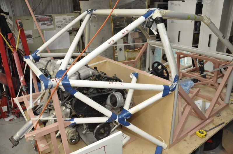
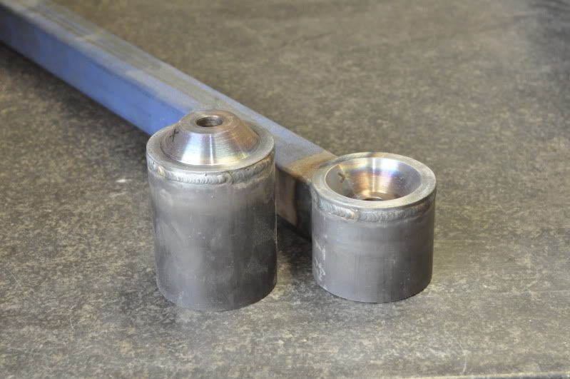
However above you will notice the longitudinal tube at the top of the rear tetrahedron has a line drawn on it. That is because it is a cone and socket joint, with a 16mm bolt down the middle to hold it together. The reasoning was that the large diameter would allow easier joining of the converging tubes as well as a larger cone/socket for the loads. The non-detachable part of this tube is also the top damper mount. The rear subframe is detachable to allow the engine and transmission to be removed/installed. The front of the lower A arm is disconnected from it's mount at the firewall, the dampers are moved to a temporary mount on the detachable section of the cone/socket. Brake lines/hand brake disconnected, rear engine mount undone. Then the six 10mm bolts and two 16mm bolts are undone and then rear subframe can be rolled back on the wheels...at least in theory and on the mockup this worked!
The different colour tubes are:
Light Blue - 44.5 x 2.5mm 350Mpa CDW
Yellow 38 x 2.5mm 350Mpa CDW
Dark blue: 50 x 1.6mm SHS 350Mpa
Magenta 40 x 1.6 round 350Mpa
Red 40 x 1.6mm SHS 350Mpa
Green 50 x 25 x 1.6mm RHS 350Mpa
So the chassis is not trying to be the lightest thing in the world...hell I'm not!
Perhaps the mockup pic here will help a little as a potential solution to addition structure, this was thought of as a solution as the same structure and be done on either side. It was not put in the above CAD model so we could see the baseline before other changes were made.
Note that this full size mockup was constructed (albeit crudely) to ensure driver room and access, individual component placement, plus to ensure adequate clearances around the engine for servicing: you can remove all manifolds and access belts etc without having to remove the engine or have two elbows on one arm. Too much time at events is spent servicing difficult to access bits in my opinion.
However above you will notice the longitudinal tube at the top of the rear tetrahedron has a line drawn on it. That is because it is a cone and socket joint, with a 16mm bolt down the middle to hold it together. The reasoning was that the large diameter would allow easier joining of the converging tubes as well as a larger cone/socket for the loads. The non-detachable part of this tube is also the top damper mount. The rear subframe is detachable to allow the engine and transmission to be removed/installed. The front of the lower A arm is disconnected from it's mount at the firewall, the dampers are moved to a temporary mount on the detachable section of the cone/socket. Brake lines/hand brake disconnected, rear engine mount undone. Then the six 10mm bolts and two 16mm bolts are undone and then rear subframe can be rolled back on the wheels...at least in theory and on the mockup this worked!
The different colour tubes are:
Light Blue - 44.5 x 2.5mm 350Mpa CDW
Yellow 38 x 2.5mm 350Mpa CDW
Dark blue: 50 x 1.6mm SHS 350Mpa
Magenta 40 x 1.6 round 350Mpa
Red 40 x 1.6mm SHS 350Mpa
Green 50 x 25 x 1.6mm RHS 350Mpa
So the chassis is not trying to be the lightest thing in the world...hell I'm not!
Edited by NeilR, 07 February 2011 - 01:30.
#32
mariner
-
- 2,401 posts
- Joined: January 07
Member
Posted 07 February 2011 - 09:15
Thanks for the photo, it nows seems clearer to a dummy like me.
If you intend to remove the whole rear sub frame to get the power pack out it seems to me that you could add triangulation on the bottom rails since no underneath access is needed. As it is the main torsional stabilty seems to be through the triangulation into the roll cage, that looks neat as it gets the roll cage to do two jobs.
One small point, there is a tube running from the right hand engine mount area up and inwards to the rear cockpit bulkhead ( the one that sort of points at black wheel in the cockpit). If that tube handles high push/pull loads it is anchored in the middle of a long and unsupported tube across the cockpit , or is that stiffened by the fuel tank panelling you mentioned earlier.
#33
NeilR
-
- 623 posts
- Joined: October 09
Member
Posted 07 February 2011 - 10:08
I have had a couple of goes adding different tubes under there - they have to be pretty slim or I have to start lifting up the power pack. I can run one decent 35mm tube from the bulkhead, under the transmission, to close to one side, effectively making a truncated A shape. I thought this could be panelled in with some sheet steel.
The secondary tetrahedron tube running to the middle of the bulkhead would be of much lighter tube and should have no real push load on it. That transverse tube is the top of the transverse box as you note. The two bulkheads are both HC panel so it should be well enough supported...the harness attaches to either side of the tetrahedron tube. It is also there to stabilise where the engine mount sits and to fix that point for the tube running back to the rear subframe....hope this all makes sense.
The rear subframe can be made much lighter, but I just have to get it done and running before I bother with this sort of detail.
Anyway it's all on hold for a couple of weeks. I have to get the next issue of Race Mag out and we've just had 180mm of rain in one day and I had a couple of inches of water through parts of the workshop...10 years of official drought and now floods, all too damn Banjo Patterson (Bush poet of 1800's who wrote about droughts and flooding rains for the non-australians out there) for my liking.
Edited by NeilR, 07 February 2011 - 10:09.
#34
Bargebear
-
- 10 posts
- Joined: October 10
New Member
Posted 07 February 2011 - 13:20
I have had a couple of goes adding different tubes under there - they have to be pretty slim or I have to start lifting up the power pack. I can run one decent 35mm tube from the bulkhead, under the transmission, to close to one side, effectively making a truncated A shape. I thought this could be panelled in with some sheet steel.
The secondary tetrahedron tube running to the middle of the bulkhead would be of much lighter tube and should have no real push load on it. That transverse tube is the top of the transverse box as you note. The two bulkheads are both HC panel so it should be well enough supported...the harness attaches to either side of the tetrahedron tube. It is also there to stabilise where the engine mount sits and to fix that point for the tube running back to the rear subframe....hope this all makes sense.
The rear subframe can be made much lighter, but I just have to get it done and running before I bother with this sort of detail.
Anyway it's all on hold for a couple of weeks. I have to get the next issue of Race Mag out and we've just had 180mm of rain in one day and I had a couple of inches of water through parts of the workshop...10 years of official drought and now floods, all too damn Banjo Patterson (Bush poet of 1800's who wrote about droughts and flooding rains for the non-australians out there) for my liking.
Actually it was Dorothea Mackellar who wrote those words.
#35
Bargebear
-
- 10 posts
- Joined: October 10
New Member
Posted 08 February 2011 - 03:26
[quote name='NeilR' date='Feb 7 2011, 21:08' post='4825606']
I think it is just about impossible to make a really neat spaceframe around a big lump like the V-6 Mitsubishi.
Maybe you should think about fabricated box section arms and rear crossmember from sheet steel or aluminium. This is what a lot of manufacturers have done in your situation. Possibly you could look at the subframe (or whatever) used on the car that the engine was out of and make up something similar but lighter to suit your purposes.
Laser cutting of sheet metal is fairly cheap these days and would simplify the job.
A similar idea would be to build a similar box structure to the metal one but in fibreglass (of a decent thickness - like half an inch or so). You could make a mockup out of solid wood to see where everything would fit. The structures can have large diameter holes cut into them to reduce weight.
With both the metal or 'glass options you can position brackets etc. exactly where they are needed - with a spaceframe you need to add tubes all over the pace to support various things.
#36
NeilR
-
- 623 posts
- Joined: October 09
Member
Posted 08 February 2011 - 09:06
Thanks for the Dorothea info...my year 10 aussie poetry classes were at least 30years ago.
I agree about the big lump! I did look at the box sections prior to this spaceframe and had a very good look at the Elise chassis. There are of course lots of issues with this too, but I am happy with where the current chassis is going at the moment and in using the FEA to guide some choices. Prior to going the tube route I did note that Lancia moved away from the box sections with the stratos to tubes with the 037...not that I'd recommend a 40 year old italian rally car is an ideal thing to model from...though I do really like both!
I agree about the big lump! I did look at the box sections prior to this spaceframe and had a very good look at the Elise chassis. There are of course lots of issues with this too, but I am happy with where the current chassis is going at the moment and in using the FEA to guide some choices. Prior to going the tube route I did note that Lancia moved away from the box sections with the stratos to tubes with the 037...not that I'd recommend a 40 year old italian rally car is an ideal thing to model from...though I do really like both!
Edited by NeilR, 08 February 2011 - 09:58.
#37
rachael
-
- 118 posts
- Joined: October 10
Member
Posted 08 February 2011 - 13:08
It is easy to get hung up (at first glance) on the red section at the extreme rear. It is actually a good design - the red tubes form a rigid, fully-triangulated truss (substituted into a panel which would otherwise contain a rectangle with diagonal) creating mounting points for the rear suspension. Likewise the pink (magenta?) section is fully triangulated albeit using significantly longer members.
I wouldn't expect the stressed skins to have much effect where they are filling triangles.
Agreed the extreme rear section looks good, but I think the connection between the red and the passenger section looks poor. It would be minimal work for the fea guy to add an extra load case putting some lateral load into the rear lower wishbone pickups which I think will also highlight that the magenta section could be improved.
#38
gruntguru
-
- 7,706 posts
- Joined: January 09
Member
Posted 09 February 2011 - 00:10
I see your point. We are coming back to the panel below the engine which seems to lack a diagonal, however I think the structure is fully constrained because (I think) the red section is a space frame in its own right and can't be "warped" like a normal panel. Ditto for the passenger compartment at the other end of the engine bay.Agreed the extreme rear section looks good, but I think the connection between the red and the passenger section looks poor. It would be minimal work for the fea guy to add an extra load case putting some lateral load into the rear lower wishbone pickups which I think will also highlight that the magenta section could be improved.
Having said all that, I agree the load path for the input you suggested would be far from optimal.
#39
Bargebear
-
- 10 posts
- Joined: October 10
New Member
Posted 09 February 2011 - 03:09
Agreed the extreme rear section looks good, but I think the connection between the red and the passenger section looks poor. It would be minimal work for the fea guy to add an extra load case putting some lateral load into the rear lower wishbone pickups which I think will also highlight that the magenta section could be improved.
I also have to agree that the red section seems very flimsily connected to the rest of the car. I think NeilR's reason is that the engine gets in the way of any lower members - but something needs to be done in this area. It is a bit surprising that FEA apparently says the structure is OK. Maybe FEA can be misleading.
Advertisement
#40
NeilR
-
- 623 posts
- Joined: October 09
Member
Posted 09 February 2011 - 10:41
No the FEA is simply answering the question that was asked of it, which is front constrained at bulkhead and load applied to rear damper mount = fig. What you are concerned of with the lateral load for the rear portion of the lower A arm is another question that will be next, along with the front damper loads into the chassis...here I'm tempted to follow Mallock's practice with the Saleen. What if the panel under the engine was filled with an alloy honeycomb panel...apart from the exhaust/sump portion.
#41
Bargebear
-
- 10 posts
- Joined: October 10
New Member
Posted 09 February 2011 - 11:18
No the FEA is simply answering the question that was asked of it, which is front constrained at bulkhead and load applied to rear damper mount = fig. What you are concerned of with the lateral load for the rear portion of the lower A arm is another question that will be next, along with the front damper loads into the chassis...here I'm tempted to follow Mallock's practice with the Saleen. What if the panel under the engine was filled with an alloy honeycomb panel...apart from the exhaust/sump portion.
You seem to have a slightly unnatural liking for alloy honeycomb panels. I think possibly AHP's may be easily damaged under the engine and be a bit of a nuisance.
An alternative could be a Lotus-style perforated-hoop bulkhead but lying flat under the engine. Perforated hoops could also be used on the sides of the engine bay if various parts of the engine/transaxle got in the way of diagonal members.
This use of perforated hoop "bulkheads" is actually suggested on page 25 of Costin and Phipps.
#42
NeilR
-
- 623 posts
- Joined: October 09
Member
Posted 09 February 2011 - 12:06
I know the melbourne based manufacturer of the panels, so it is easy to get, plus it is very stiff out of plane.
Your suggestion is interesting!
Your suggestion is interesting!
#43
mariner
-
- 2,401 posts
- Joined: January 07
Member
Posted 09 February 2011 - 12:25
There is , I think, some truth in the comment about using AHP near the engine. The stuff is great but it IS very easily damaged even by tools etc. if you use the stuff with 0.5mm skins. That stuff, in 25mm thickness , is strong and weighs about 1lb/sq ft using imperial. If you go up much in skin thickness the weight climbs fast so, unless it is a very highly stressed area th 0.5mm skin stuff is what you may end up using.
So whilst AHP is good for the cockpit area it may not be good for near the engine ( or used vertically near wheelwells with stones flying). Also the bonding tempearture on AHP may get exceeded near exhausts.
As suggested perforated bulkheads are one way around the bottom plane stiffening problem with a great big sump in the way. Another way is a single sheet paenl with a large circular hole in the middle , well flanged. You make the hole big enough to drop the sump into to get low CG and put a decent size lip on it to stiffen the sheet.
An example is shown here in a recreation of the Chapparal 2E
http://www.chaparral...e/carbuild1.jpg
If you look just behind the cross member in the middle of the chassis you can see the circular flanged hole under the engine.
Admittedly a very old design but flat sheet is all they had so they learned to use it well and the fabrication techniques are now fairly suitable fro "amateur" builds.
#44
rachael
-
- 118 posts
- Joined: October 10
Member
Posted 09 February 2011 - 12:38
No the FEA is simply answering the question that was asked of it, which is front constrained at bulkhead and load applied to rear damper mount = fig. What you are concerned of with the lateral load for the rear portion of the lower A arm is another question that will be next, along with the front damper loads into the chassis...here I'm tempted to follow Mallock's practice with the Saleen. What if the panel under the engine was filled with an alloy honeycomb panel...apart from the exhaust/sump portion.
If the panel under the engine is working in shear you would be much better off just using regular ally sheet rather than honeycomb. If the sheet has the same thickness as the honeycomb skins then it will have the same shear stiffness as the honeycomb version. The advantages of using plain sheet are cost, space, ease of installation and if it runs anywhere near the exhaust probably durability as well.
Look here for another interesting technique that motor manufacturers are using structural origami
Edited by rachael, 09 February 2011 - 12:46.
#45
mariner
-
- 2,401 posts
- Joined: January 07
Member
Posted 09 February 2011 - 13:57
That is very interesting. Long ago there was an Italian company, Salvanini,who came only half way to this by automated sheet folding. The fixing remained manual weld.If the panel under the engine is working in shear you would be much better off just using regular ally sheet rather than honeycomb. If the sheet has the same thickness as the honeycomb skins then it will have the same shear stiffness as the honeycomb version. The advantages of using plain sheet are cost, space, ease of installation and if it runs anywhere near the exhaust probably durability as well.
Look here for another interesting technique that motor manufacturers are using structural origami
The big advantage was, as with IOL , reduced stock holding/space by bringing the sheet metal roll not the stamped part to the assembly site. From an ROI viewpoint you could sometimes almost pay for the machine just by financing cheap sheet metal stock vs finished parts.
Salvanini had one big disadvantage which seems to still be with IOL to some extent two dimensional curves are hard to acheive if at all. No problem for inner panels as shown but it may limit use on external panels and , I suppose, some of the stiffness benefits of deep drawing may be missed. Nonetheless a very clever idea.
BTW does anybody know if any racing people use hydroforming to shape parts at all? I know it is used on the Corvette frame which is retained in the racing Corvette and on SUV frames but I do not know if it can be used in low volume.
#46
NeilR
-
- 623 posts
- Joined: October 09
Member
Posted 09 February 2011 - 21:31
There used to be a quite interesting 'Super Rod Magazine' article on the Mosler website that showed the mosler chassis construction. This was cnc cut composite honycomb panels that slotted together, which I thought was quite neat.
I have not seen any hydro-formed race car bits - perhaps too expensive for such small quantities?
A friend of mine runs a steel engineering business and he has suggested two laser cut 1mm steel sheets with overlapping flanges welded together. There will be a solution, but to run through the options for FEA: current setup, current with diagonals is possible, both with sheet panel.
#47
Bargebear
-
- 10 posts
- Joined: October 10
New Member
Posted 10 February 2011 - 05:27
[quote name='mariner' date='Feb 9 2011, 23:25' post='4829753']
There is , I think, some truth in the comment about using AHP near the engine. The stuff is great but it IS very easily damaged even by tools etc. if you use the stuff with 0.5mm skins. That stuff, in 25mm thickness , is strong and weighs about 1lb/sq ft using imperial. If you go up much in skin thickness the weight climbs fast so, unless it is a very highly stressed area th 0.5mm skin stuff is what you may end up using.
So whilst AHP is good for the cockpit area it may not be good for near the engine ( or used vertically near wheelwells with stones flying). Also the bonding tempearture on AHP may get exceeded near exhausts.
As suggested perforated bulkheads are one way around the bottom plane stiffening problem with a great big sump in the way. Another way is a single sheet paenl with a large circular hole in the middle , well flanged. You make the hole big enough to drop the sump into to get low CG and put a decent size lip on it to stiffen the sheet.
I think all the suggested ideas so far would work. However for an "amateur" build the perforated bulkhead would seem to be best. The construction techniques of sheet steel work with welding or nickel bronze brazing to steel tubes is straightforward and suited to amateur construction. It also more compatible with the steel tube spaceframe of the rest of the car.
It is very easy to become bedazzled by "F1" techniques like AHP and carbon fibre/epoxy etc. when traditional spaceframe techniques are probably almost as good and a lot easier to manage with limited resources.
#48
NeilR
-
- 623 posts
- Joined: October 09
Member
Posted 10 February 2011 - 09:04
Well I am neither bedazzled by AHP nor carbon, nor consider either F1 materials. I have some experience with carbon making wings for sports sedans etc...but I have not mentioned using it in this project as far as I know. AHP has been an 'amateur' material since the 1980's, the challenge in Australia is that it has not been readily available as the market has always been too small. http://alexandria.tu...ooks/627108.pdf
Edited by NeilR, 10 February 2011 - 09:10.


