

Converting single throttle manifold to multi ITBs.
Started by
Wirra
, Mar 08 2011 11:23
11 replies to this topic
#1

Wirra
-
- 1,333 posts
- Joined: December 08
Member
Posted 08 March 2011 - 11:23
What issues might one face in utilizing two banks of 4 independent throttle bodies (itb), taken from two similar motorcycle engine, to create 8 itbs on a production V8 engine? The engine is a GM, 5.7ltr LS1 with efi. The fabrication issues I can work through but I‘m just wondering what difficulties I might experience in having the engine run and perform properly. Thank you.
Advertisement
#2
kikiturbo2
-

- 879 posts
- Joined: December 04
Member
Posted 08 March 2011 - 16:35
That depends on the ECU you'll run.. I presume you will not run a MAF sensor, but rather go for either MAP sensor for load measurement, or go straight to Alpha-N system, (i.e. RPM vs. throttle position.). If you decide to use a MAP sensor as a engine load imput, you'll have to make some sort of a "vacuum" acumulator with feeds from various throttles to have a stable vaccum for MAP measurement.
If you go for Alpha-N, that should work fine at large throttle openings, but might be tricky at low load..
I do not follow the standalone ECU market, so do not know if there are systems that support both Alpha-N and MAP based mapping AT THE SAME TIME, (in other words MAP at low load and ALpha-N at large loads), as do some motorcycle ECU's.
#3
ralt12
-

- 286 posts
- Joined: December 04
Member
Posted 08 March 2011 - 18:57
There is some discussion here:
http://www.ls1tech.c...ls-engines.html
and also here:
http://www.ls1tech.c...-questions.html
and here:
http://www.ls1tech.c...-too-small.html
These are just scratching the surface, really, as there is quite a bit of discussion on the LS board. Personally, I have a great deal of desire for one of the Harrop ITB's (here):


or Steve Kinsler's, (here):


I need to win the lottery for those babies....
http://www.ls1tech.c...ls-engines.html
and also here:
http://www.ls1tech.c...-questions.html
and here:
http://www.ls1tech.c...-too-small.html
These are just scratching the surface, really, as there is quite a bit of discussion on the LS board. Personally, I have a great deal of desire for one of the Harrop ITB's (here):
or Steve Kinsler's, (here):
I need to win the lottery for those babies....
#4
ray b
-

- 2,969 posts
- Joined: January 01
Member
Posted 08 March 2011 - 19:07
some people have done that on caddy northstar motors using kawasuckie bits
#5
carlt
-

- 4,169 posts
- Joined: June 09
Member
Posted 08 March 2011 - 22:01
or Steve Kinsler's, (here):
Bet that plays a fine tune
#6
gruntguru
-

- 7,706 posts
- Joined: January 09
Member
Posted 08 March 2011 - 22:36
Motec will do that. You can also use one as the main map and apply corrections based on the other. (Useful on turbo engines where a given throttle/rpm site will not always have the same boost/airflow)I do not follow the standalone ECU market, so do not know if there are systems that support both Alpha-N and MAP based mapping AT THE SAME TIME, (in other words MAP at low load and ALpha-N at large loads), as do some motorcycle ECU's.
#7
ralt12
-
- 286 posts
- Joined: December 04
Member
Posted 09 March 2011 - 05:19
Bet that plays a fine tune
It'd be a shame to cover it up with air cleaners, no?
#8
Canuck
-

- 2,413 posts
- Joined: March 05
Member
Posted 12 March 2011 - 23:16
Seems to me the latest iteration of Megasquirt can do mixed mapping as suggested above. MS3 perhaps? I seem to recall in my earlier questions along a similar vein that there was some discussion over potential air leakage problems at idle.
#9
RB30X
-

- 4 posts
- Joined: March 11
New Member
Posted 14 March 2011 - 00:11
That depends on the ECU you'll run.. I presume you will not run a MAF sensor, but rather go for either MAP sensor for load measurement, or go straight to Alpha-N system, (i.e. RPM vs. throttle position.). If you decide to use a MAP sensor as a engine load imput, you'll have to make some sort of a "vacuum" acumulator with feeds from various throttles to have a stable vaccum for MAP measurement.
The plan is to use the existing MAP sensor placed on a small plenum with vacuum feeds from each individual runner as you mentioned.
The PCM (or Powetrain Control Module) for the LS1 is very handy at tuning all intake set ups as is, even forced induction.
I just received two 2" - 2.5" alloy reducers to trial as runners. The cathedral shaped intake ports on the alloy head are proving to be the hardest thing about his little project.
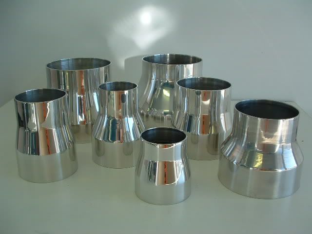
The 2.5" alloy pipe can be shaped to fill the exact size of the taller and narrower cathedral port. Rather than butcher the outside of the pipe I was thinking of welding a few pieces of steel together in a short taper to the shape of the cathedral port then using a press to press the alloy pipe over the shaped tapered steel to resemble the port once removed (if that makes sense). Four of these would be welded to a head flange on each bank.
I haven't decided whether to just use 2" hose and hose clamps to attach the throttle bodies to the other end of the runners, or make up flanges for both sides. One to weld to the throttle bodies and one to weld to the manifold. This would mean more welding and the whole hose and hose clamp thing looks a bit old school anyway.
For what its worth, this LS1 is in an old Datsun 240Z.
cheers
#10
mariner
-

- 2,401 posts
- Joined: January 07
Member
Posted 23 March 2011 - 09:11
As a matter of curiosity if you have an engine with an OEM ECU and direct injection and you fit a turbo could you use a seperate Motec system injecting into the manifold just for boost conditions?
If I understsand it right Motec uses just rpm and MAP but is very programmable. So you get the advantage of leaving the stock ECU and parameters alone which avoids lots of "hacking" and would, presumably , let the car sail through any emissions tests as on light load the turbos don't run much and the stock settings wil hold emissions.
Then you put the MAP sensor for the Motec in the manifold and programme it to fire the extra boost fuel via a seperate set of injectors screwed into the manifold. It would need an RPM sensor as well I guess.
I can see that knock needs controlling with boost but that should be handled by the stock ECU's already fitted knock sensors without any need to link to the Motec unit.
I expect that somebody has already done just this??
#11
RB30X
-
- 4 posts
- Joined: March 11
New Member
Posted 23 March 2011 - 09:50
The oem ecu can already handle boosted engines, just needs bigger injectors and a 2 bar map sensor.
#12
Magoo
-

- 3,856 posts
- Joined: October 10
Member
Posted 23 March 2011 - 17:41
As a matter of curiosity if you have an engine with an OEM ECU and direct injection and you fit a turbo could you use a seperate Motec system injecting into the manifold just for boost conditions?
If I understsand it right Motec uses just rpm and MAP but is very programmable. So you get the advantage of leaving the stock ECU and parameters alone which avoids lots of "hacking" and would, presumably , let the car sail through any emissions tests as on light load the turbos don't run much and the stock settings wil hold emissions.
Then you put the MAP sensor for the Motec in the manifold and programme it to fire the extra boost fuel via a seperate set of injectors screwed into the manifold. It would need an RPM sensor as well I guess.
I can see that knock needs controlling with boost but that should be handled by the stock ECU's already fitted knock sensors without any need to link to the Motec unit.
I expect that somebody has already done just this??
Unless you are in tight with the OE, DI is difficult to fiddle with. The pressure is very high, the pulsewidth can be very low, timing is hyper-critical, and some systems use multiple events per cycle. And everything is proprietary and sensitive. Your idea, a secondary injector array and piggybacked controller or ECM, would bypass a number of headaches and there is no reason it can't work reasonably well. One or two aftermarket firms say they can supply ECUs that will support DI but from what I have seen and heard, not really, not yet.


