Several respected engine designers/builders have commented that "connecting rods are simply a mechanism for connecting the piston to the crankshaft", and that the length of the connecting rod (within limits) may not be material. Perhaps of greater importance is the location of the ring pack and piston pin on the piston, according to these same luminaries.
So, this begs the question: "What is the optimum ring pack / piston pin location? Is there a formula?

Optimal piston pin location?
Started by
Paul Vanderheijden
, Jan 04 2012 15:29
17 replies to this topic
Advertisement
#2

Greg Locock
-

- 6,495 posts
- Joined: March 03
Member
Posted 04 January 2012 - 22:13
Paul Vanderheijden, on Jan 5 2012, 02:29, said:
Several respected engine designers/builders have commented that "connecting rods are simply a mechanism for connecting the piston to the crankshaft", and that the length of the connecting rod (within limits) may not be material. Perhaps of greater importance is the location of the ring pack and piston pin on the piston, according to these same luminaries.
So, this begs the question: "What is the optimum ring pack / piston pin location? Is there a formula?
Pretty much agree with the first part. The Falcon I6 has a truly horrible L/r ratio and except for people who care about engine noise (me at the time) it doesn't seem to matter.
The way I remember it, and I haven't worked on engines for 15 years, is you place the rings as high as you can while maintaining adequate strength above the top ring. That is mostly driven by emissions, so for a hand built engine may not apply.
piston pin off-axis location aka gudgeon pin offset aka little end offset is fine tuned on production engines to minimise cold engine clatter. This is done experimentally - there are formulas but not definitive ones. There may be performance advantages in other locations.
I believe our friend Manolis has a great program for investigating inertia effects in piston/con rod assemblies, http://www.pattakon....attakonEduc.htm
Very much depends on what sort of engine you are building.
#3
Tony Matthews
-

- 17,519 posts
- Joined: September 08
Member
Posted 04 January 2012 - 23:59
Greg Locock, on Jan 4 2012, 22:13, said:
What about wrist pin offset?piston pin off-axis location aka gudgeon pin offset aka little end offset ...
#4
bigleagueslider
-

- 1,235 posts
- Joined: March 11
Member
Posted 05 January 2012 - 00:59
Paul Vanderheijden, on Jan 4 2012, 07:29, said:
Several respected engine designers/builders have commented that "connecting rods are simply a mechanism for connecting the piston to the crankshaft", and that the length of the connecting rod (within limits) may not be material. Perhaps of greater importance is the location of the ring pack and piston pin on the piston, according to these same luminaries.
So, this begs the question: "What is the optimum ring pack / piston pin location? Is there a formula?
Paul Vanderheijden,
With conrod length, as long as the kinematics work OK, there's not much overall performance difference with small changes in length. So all other things being equal, a shorter, lighter rod would seem to be preferable.
Wrist pin axial location is mostly academic. Below the oil control ring groove on 4-stroke pistons.
As for ring location, there is quite a bit of difference between gasoline and diesel engine pistons. Gas engine pistons tend to keep the top compression ring fairly close to the deck, in order to minimize crevice volume and HC emissions. Turbodiesel pistons, on the other hand, tend to position the top ring further away from the deck. This allows oil cooling all around the inside surface of the top piston ring groove. The second ring is also usually spaced further away from the top ring than normal. This creates a gas buffer volume behind the top ring, and helps to prevent flutter.
slider
#5
MatsNorway
-

- 2,831 posts
- Joined: December 09
Member
Posted 05 January 2012 - 09:14
bigleagueslider, on Jan 5 2012, 01:59, said:
there is quite a bit of difference between gasoline and diesel engine pistons. Gas engine pistons ...
Please don`t use the word gas when you talk about petrol.... gas means something like propane and hydrogen.
#6
Engineguy
-

- 989 posts
- Joined: February 01
Member
Posted 05 January 2012 - 09:34
MatsNorway, on Jan 5 2012, 04:14, said:
Please don`t use the word gas when you talk about petrol.... gas means something like propane and hydrogen.
Perhaps on your side of the world. The word petrol is virtually unused here. If you pull into a gas station in the USA and ask for petrol, they'd look at you funny
 and tell you they don't sell petrol... only unleaded gas, diesel, and maybe kerosene. Propane is called propane, and of course hydrogen doesn't really exist to the general public.
#7
Catalina Park
-

- 6,895 posts
- Joined: July 01
Member
Posted 05 January 2012 - 09:39
Is propane really propane? Or is it a blend of Propane and Butane like we have here?
#8
Engineguy
-
- 989 posts
- Joined: February 01
Member
Posted 05 January 2012 - 10:18
Catalina Park, on Jan 5 2012, 04:39, said:
Primarily propane but not pure.Is propane really propane? Or is it a blend of Propane and Butane like we have here?
Per Wikipedia:
Commercially available "propane" fuel, or LPG, is not pure. Typically in the USA and Canada, it is primarily propane (at least 90%), with the rest mostly ethane, propylene, butane, and odorants including ethyl mercaptan. This is the HD-5 standard, (Heavy Duty-5% maximum allowable propylene content, and no more than 5% butanes and ethane) defined by the American Society for Testing and Materials by its Standard 1835|http://hd5propane.com/%7C for internal combustion engines. Not all products labelled "propane" conform to this standard. In Mexico, for example, the butane content is much higher.
North American barbecue grills powered by propane cannot be used overseas.[citation needed] The "propane" sold overseas is actually a mixture of propane and butane. The warmer the country, the higher the butane content, commonly 50/50 and sometimes reaching 75% butane.
As far as IC engines, very little on-road (i.e. "Autogas") vehicle use in US, but mucho forktrucks, factory floorsweepers, floor polishers for large stores, probably Zambonis, etc..
#9
Magoo
-

- 3,856 posts
- Joined: October 10
Member
Posted 05 January 2012 - 10:41
On many current engines the oil ring groove runs through the pin bore. This looks totally wrong but works fine if the oil ring rails and expander are supported properly.
Apropos of nothing at all except conversational value, on some radial aircraft engines the oil ring groove was completely below the pin bore.
Modern practice is to place the top ring groove as high on the piston as practical to reduce crevice volume (for reduced hydrocarbon emissions) on production engines and improve gas sealing on performance applications. From there, the ring set (three rings, I'm assuming) selected will determine the ring stack vertical height, more or less. Vertical spacing or gas/fluid volume between the rings influences ring operation. (Web search "Napier second ring.")
"Connecting rods are simply a mechanism for connecting the piston to the crankshaft." Yes, that's pretty much it on contemporary engines due to, among other things, the general range of stroke, bore/stroke ratios, and rod/stroke ratios in use, etc. However, it's not so true for say, a British valve-in-head six.
#10
Lee Nicolle
-

- 11,292 posts
- Joined: July 08
Member
Posted 06 January 2012 - 03:29
Rod ratio, rod legth to stroke is important, more so for a performance engine.Long rod generally = torque.
But so many engines are built to be small so have little short rods and blocks. Particularly Vee engines.
Though the question is how high the pin can be in the piston. I have never seen a 'modern' petrol engine with the pin above the oil ring as a std engine. And I doubt that the durability is there for high km engines ever with the pin behind the oil ring. That is the same reason the top ring is not higher either. For performance, and emissions having the top ring high is good, but not really that durable as the ring will not cool properly, loses tension and effectivness. That really even includes endurance racing.
In the past some people have put the pistons in backwards, to advoid the ' drag' of the pin offset. But very minimal gains and the pistons and bores wear out fast!
A longer rod will park the piston at TDC and BDC for a greater amount of crank degrees meaning the flame front has more time to build up pressure to push the piston down. And sometimes [depending on heads, exhaust and cam] it helps expell the exhaust more too.Which can be good or bad.
For mine having the oilring over the pin will never be quite as durable on a road engine but on a race engine within reason having a longer rod normally helps power and torque.
#11
Paul Vanderheijden
-
- 65 posts
- Joined: December 07
Member
Posted 06 January 2012 - 04:31
Thank you for all of the insight. Here is some more information that hopefully will assist in giving a bit more background.
Displacement 1 litre
OHV - 2 valve per cylinder
Bore 65mm
Stroke 74mm
Rod length - variable between 110 and 117mm
Ring stack 13.4mm
Piston length 39mm Full skirt design
Current HP is 119 HP @ 8000 RPM.
Peak torque is at 6200 RPM
With the longest rod (117mm) there is 1mm of material between the pin bores and the oil ring groove. Top ring land is 4mm. Rings are 1.22, 1.22, 2.52mm widths. Top ring barrel faced (chrome) steel, second ring ductile iron, oil control expander with two steel scrapers.
The stock rod length is 110 which give a rod/stroke ration of 1.49:1. THe longest rod at 117mm would give a rod/stroke ratio of 1.58:1.
Any further insight would be greatly appreciated.
Paul
#12
Paul Vanderheijden
-
- 65 posts
- Joined: December 07
Member
Posted 06 January 2012 - 04:33
Additional info.
Bores are offset to the crank centerline by 2mm, and the pistons have no piston pin offset.
Paul
Bores are offset to the crank centerline by 2mm, and the pistons have no piston pin offset.
Paul
#13
manolis
-

- 941 posts
- Joined: May 03
Member
Posted 07 January 2012 - 05:03
Hello.
In case it helps:
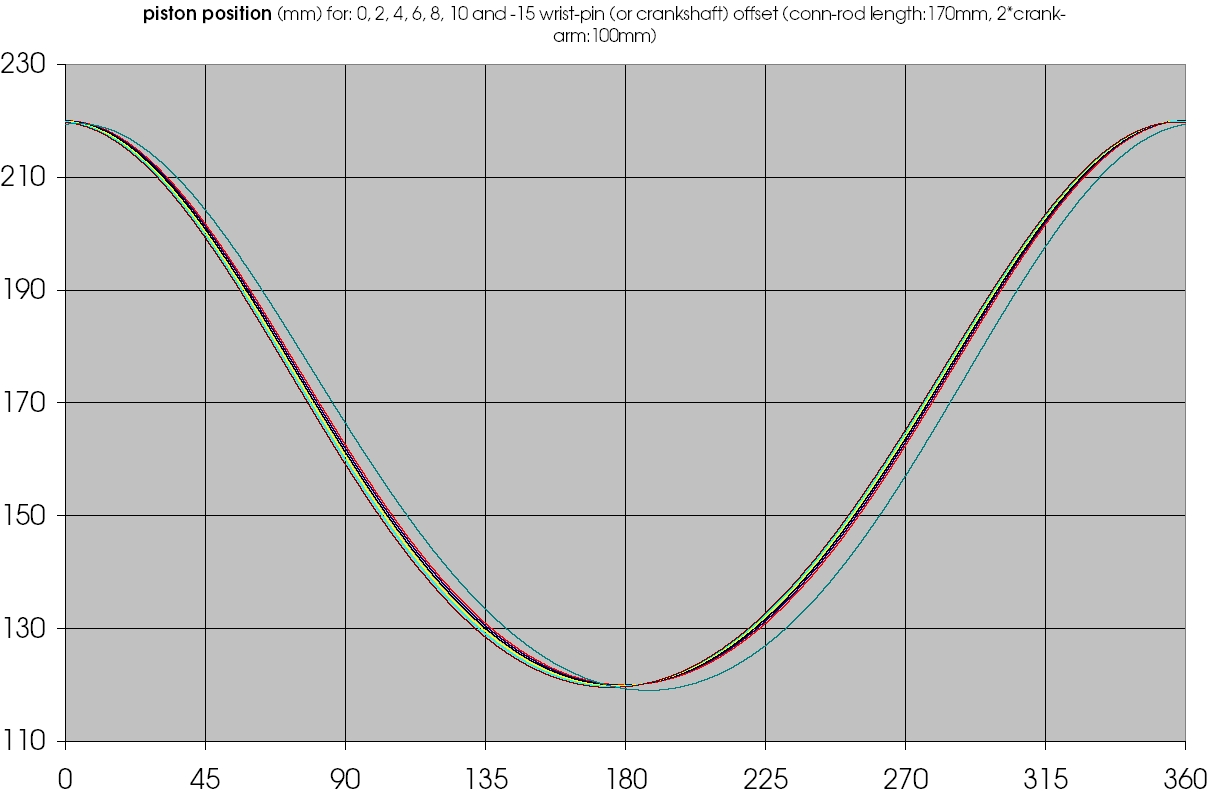
The plot below is the piston position versus the crankshaft angle (the PDF is at offset piston position pdf )
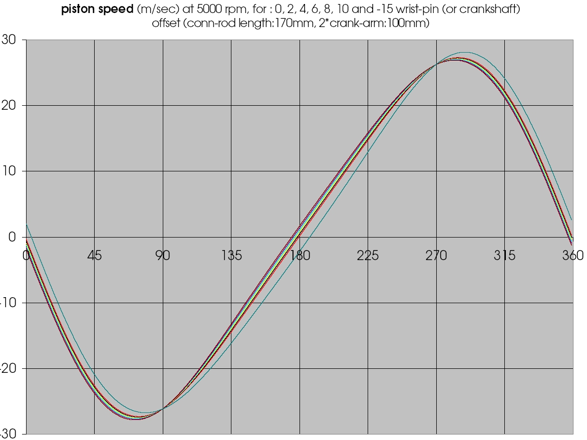
The plot below it is the piston speed versus the crankshaft (the PDF is at offset piston speed pdf )
The plot below it is the piston acceleration versus the crankshaft (the PDF is at offset piston acceleration pdf )
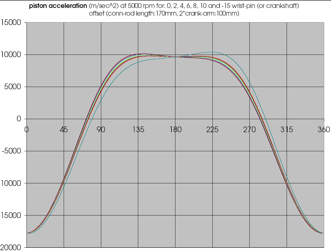
The red curves are for zero offset.
Here is the excel file the plots came from ( you can play with the con-rod length, with the stroke, with the offset etc):
http://www.pattakon....t_wrist_pin.xls.
Mathematically, either you have a 5 mm offset of the wrist pin relative to the cylinder axis, or a -5 mm offset of the crankshaft relative to the cylinder axis, it is the same thing.
But inside the engine there is difference.
For instance, in the first case the gas pressure force on the piston crown tries to rotate the piston about the wrist pin, in the second case there is no such effect.
With the offset the thrust force can change form: you can decrease, for instance, the thrust force during the expansion (i.e. when it maximizes), increasing it during the compression.
The balance of the engine changes.
The expansion rate changes.
Etc.
For the con-rod to stroke ratio:
The engines with the top brake thermal efficiency (above 50%) are the giant cross-head two-stroke marine engines. Their typical cor-rod to stroke ratio is somewhere between 1.1 to 1.25
Thanks
Manolis Pattakos
In case it helps:
The plot below is the piston position versus the crankshaft angle (the PDF is at offset piston position pdf )
The plot below it is the piston speed versus the crankshaft (the PDF is at offset piston speed pdf )
The plot below it is the piston acceleration versus the crankshaft (the PDF is at offset piston acceleration pdf )
The red curves are for zero offset.
Here is the excel file the plots came from ( you can play with the con-rod length, with the stroke, with the offset etc):
http://www.pattakon....t_wrist_pin.xls.
Mathematically, either you have a 5 mm offset of the wrist pin relative to the cylinder axis, or a -5 mm offset of the crankshaft relative to the cylinder axis, it is the same thing.
But inside the engine there is difference.
For instance, in the first case the gas pressure force on the piston crown tries to rotate the piston about the wrist pin, in the second case there is no such effect.
With the offset the thrust force can change form: you can decrease, for instance, the thrust force during the expansion (i.e. when it maximizes), increasing it during the compression.
The balance of the engine changes.
The expansion rate changes.
Etc.
For the con-rod to stroke ratio:
The engines with the top brake thermal efficiency (above 50%) are the giant cross-head two-stroke marine engines. Their typical cor-rod to stroke ratio is somewhere between 1.1 to 1.25
Thanks
Manolis Pattakos
Edited by manolis, 07 January 2012 - 05:07.
#14
Paul Vanderheijden
-
- 65 posts
- Joined: December 07
Member
Posted 08 January 2012 - 14:13
Manolis
THank you for the spreadsheet. I will have a play with it.
THank you for the spreadsheet. I will have a play with it.
#15
J. Edlund
-

- 1,323 posts
- Joined: September 03
Member
Posted 13 January 2012 - 12:55
A higher rod to stroke ratio tend to offer less side load on the cylinderwalls and reduce friction.
A reduced compression height on the piston tend to reduce piston weight.
A reduced compression height on the piston tend to reduce piston weight.
#16
malbear
-

- 309 posts
- Joined: September 02
Member
Posted 13 January 2012 - 20:14
J. Edlund, on Jan 13 2012, 12:55, said:
wouldn't a reduced hight put most of the side thrust directly onto the rings and a pin location lower down put the side thrust onto the piston skirt ?A higher rod to stroke ratio tend to offer less side load on the cylinderwalls and reduce friction.
A reduced compression height on the piston tend to reduce piston weight.
Bring back the may fireball and a flat top piston all is forgiven
#17
Paul Vanderheijden
-
- 65 posts
- Joined: December 07
Member
Posted 14 January 2012 - 15:15
After doing some further research, taking into account the comments of J. Edlund, Manolis and Lee Nicolle, it would appear that the piston (66-68mm diam.) used in the Honda CRF150R is very close to a design that might work. While this is a 3 ring piston, I would probably go with a 2-ring configuration (.8mm top and a 1.5mm U-flex oil control ring) This would result in a ring pack of 13.3mm tall, with the top of the 14mm pin bore being .5mm below the oil ring groove. Skirt length would be 32mm. I would keep the piston crown thickness at 5mm so as to allow some leeway for machining valve reliefs as required.
From the sample piston that I modified, this would give a weight for the piston with pins, rings and circlips of 175 gram. This would be a 45 gram reduction over the current piston weight. The connecting rod that I am using at the moment is a steel unit from Saenz in Argentina and in 117mm long form weighs in at 340 gram, complete with bolts. Looking at the connecting rod from the Honda CRF150R motor, it may be that the current shape/dimensions of the Saenz connecting rod are somewhat "club-like". I will have a discussion with them as to whether any reductions in section are possible.
The one question that does spring to mind is whether a 14mm wrist pin could be retained, or whether one of larger diameter is indicated? The CRF10R motor, with its 44mm stroke, revs to 12,500 RPM and at that engine speed would have a piston speed of 59.4 ft/sec-sec or 3568 ft/min. Comparatively, my Fiat based motor runs to 8500 RPM and has a 74mm stroke. This would result in a piston speed of 68.8 ft/sec-sec or 4126 ft/min.
Using the spreadsheet, so generously provided by Manolis, it would appear that for the Honda engine combination the max Gs at TDC would be -4731g. Using the the same spreadsheet with the rod/stroke/RPM characteristics of the Fiat motor gives a result of -8470 Gs at TDC. This is 1.79 times the G-force at TDC. The force approaching BDC is only in the neighborhood of 4500g, so this is within the max. TDC forces seen in the Honda application @ TDC.
Currently, with a heavier piston (220 gram) I am using a tapered bore, 1mm wall thickness at the outer end and 2.4mm thickness in the "span section between piston bosses), 50mm long, 18mm diameter pin. Pin boss engagement on the pin is approx 13mm at each end of the pin. The span between pin bosses is 24mm for a connecting rod with a small end width of 18mm. This pin shows little if any wear, even after a full season of racing.
The Honda pin is a straight wall pin, with a 2.5mm wall thickness, supported in two piston bosses 16mm wide, with about the same 13mm of pin engagement on each side. The small end of the Honda rod is 17mm wide with span between the pin posses being 18.4mm.
I see two issues. 1) Determining if the reduced diameter 14mm pin of the Honda piston will take the increased g-force loadings and: 2) Will the reduced small end width/diameter of the pin end of the conrod be a problem either due to g-forces or combustion compression forces? Does anyone have any programs for quantifying this?
#18
manolis
-
- 941 posts
- Joined: May 03
Member
Posted 14 January 2012 - 15:36
J. Edlund, on Jan 13 2012, 12:55, said:
A higher rod to stroke ratio tend to offer less side load on the cylinderwalls and reduce friction.
A reduced compression height on the piston tend to reduce piston weight.
This Man-B&W 2-stroke low-speed cross-head marine engine:
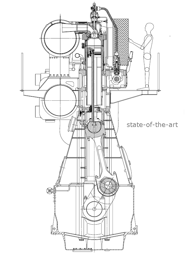
has a small con-rod to stroke ratio (less than 1.2),
171 gr/KWh fuel efficiency,
and a big (4.4) stroke to bore ratio (350mm bore, 1550mm stroke)
A dedicated slider (cross-head architecture) takes the thrust loads; the oil quantity and oil pressure are optimized in the cross-head, outside the cylinder liner.
If they could improve the overall fuel efficiency by a longer connecting rod, they would use it. In merchant boats the top fuel efficiency is a must.
A trunk-piston four-stroke cannot operate with a similar bore to stroke ratio.
The cylinder - cylinder liner of the 4-stroke suffers from heavy thrust loads.
The 2-stroke, on the other hand, has the problem of the lubrication and of the scuffing resistance.
Take a look at PatMar(ine) engine
wherein the operation of the PatMar engine:
is presented.
It is a through scavenging (uniflow) cross-head two stroke with true 4-stroke lubrication and scuffing resistance.
Thanks
Manolis Pattakos


