
Edited by MatsNorway, 11 July 2012 - 18:09.

Advertisement

Member
Posted 12 July 2012 - 00:05

Member
Posted 12 July 2012 - 01:35

Member
Posted 12 July 2012 - 02:03

Member
Posted 12 July 2012 - 03:29
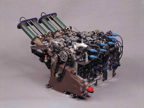
This was in production for a few years
http://media.photobu.../DSCF2280-1.jpg
Switchover speed was around 3500 rpm, that's the vac actuator at the front.
Member
Posted 12 July 2012 - 04:42
Variable-length inlet tuning the hard way.
Member
Posted 12 July 2012 - 05:08
Member
Posted 12 July 2012 - 06:24
It's not really a "variable" system. Instead it's more of a "binary" system. The relative change in tuned length between the two inlets is also a bit excessive. Even for a very high rpm F1 engine, the length of the lower inlets looks much too short to be of benefit. I think it's just a poorly considered design by some garage mechanic.
Member
Posted 12 July 2012 - 06:57
Member
Posted 12 July 2012 - 13:04
The photos are a rerofit onto a pre 90s Ford (Australia) Falcon, the manifold was fitted to i6 Falcons from about 2002 onwards. I doubt we'll ever see 6 butterflies on a single spindle again!
I can't find the graph showing the torque curve with the butterflies open and closed. At the time I was working on engine noise, and it was with fear in my heart that I leant over one on the chassis dyno, and flipped the butterfly backwards and forwards , and decided there was no NVH issue! I'm still a bit surprised by that.

Member
Posted 13 July 2012 - 08:44
This was in production for a few years
http://media.photobu.../DSCF2280-1.jpg
Switchover speed was around 3500 rpm, that's the vac actuator at the front.

Member
Posted 13 July 2012 - 22:43
"had" being the operative word, I suspect.peugeot, as well as some other europeans had similar systems..
Member
Posted 13 July 2012 - 23:46
By far most variable inlet systems are "binary." Never assume that two tract lengths are tuned to the same wave. You are looking at an old Nissan factory setup, so that's what you get for thinking.
Member
Posted 15 July 2012 - 00:27
"had" being the operative word, I suspect.

Member
Posted 15 July 2012 - 18:50
Edited by MatsNorway, 15 July 2012 - 18:51.
Member
Posted 16 July 2012 - 02:06
Please note that the engine in the picture is a Wankel. Why a servo actuated tract like in the picture is not more common on sporty cars is a tiny bit surpricing for me. At least on a wankel who has no vaiable intake timing like VTEC and such. (as far as i know)
Member
Posted 16 July 2012 - 11:09
Using a runner length tuned for anything other than first order harmonics is usually not worth the effort since higher order harmonics tend to be far less energetic.
Member
Posted 19 July 2012 - 01:37
Really. How long does it need to be at 4000 rpm, do you reckon.
Member
Posted 19 July 2012 - 03:41
Beg your pardon, but how long does what need to be at 4000 rpm?
Advertisement
Member
Posted 21 July 2012 - 02:16
Inlet tract. As you know.
Member
Posted 21 July 2012 - 06:53
Magoo,
Sorry, I understand your question now.
While the precise answer is quite complicated, the simple answer is as long as it takes for pressure wave to travel up the runner duct from the intake valve face (at INOP) to the trumpet lip, and back again to the intake valve face (close to INCL). The acoustic pressure wave travels along the manifold runner at sonic velocity. The negative pressure pulse is created when the intake valve opens. It travels along the inlet runner, with its relatively uniform cross section, until it reaches the trumpet lip. At the trumpet lip the duct cross section changes abruptly, and this causes a reversion of the pressure wave. The reflected pressure wave is now positive and travels back down the inlet runner. Ideally it arrives at the inlet valve face just a bit before it closes, and the higher pressure pulse forces a bit more air/fuel into the cylinder at the last instant.
The basic process is dependent upon the speed of sound at the inlet manifold conditions, and the valve event time duration. In most cases, the primary mode is the only one worth considering. So an isolated intake runner length tuned to take advantage of the primary mode at 4000 rpm should be roughly 1/2 the distance a pressure wave will travel at sonic velocity during the time between INOP and INCL at 4000 rpm. This time period would be around .013 seconds at 4000 rpm with typical race engine valve timings.
In reality it's not quite so simple, but I think you can get the basic concept. And of course I should also point out that I'm no expert on the subject. So if I've made an error in my explanation, maybe someone can correct me.
Regards,
slider

Member
Posted 21 July 2012 - 09:34
...In most cases, the primary mode is the only one worth considering...

Member

Member
Posted 21 July 2012 - 10:27


Member
Posted 21 July 2012 - 11:50

Tech Forum Host
Posted 21 July 2012 - 13:49
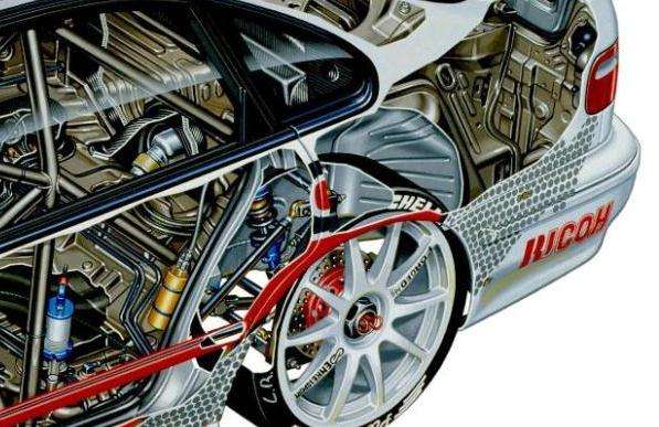
Assuming the cross section of the Ferrair V - 10 Tony has posted is fully accurate two things look interesting.
- The use of cam followers on such a high reving engine with Pneumatic valve springs
Member
Posted 21 July 2012 - 14:19
Member
Posted 22 July 2012 - 14:10
Member
Posted 22 July 2012 - 15:32
Finger followers became universal or nearly so around 10 years ago in F1. Here's John Judd on the rationale:
"I think you need finger followers in Formula One now. The use of air springs means that the spring itself is no longer a problem. With wire springs you got pushed into a corner between spring design and valve lift. You had to compromise badly whereas with air springs there is no real compromise - you just have to make sure that you don't overload the cam/tappet interface.
"As much as 17mm of valve lift is not out of court these days [1998]. To get the valve open to that amount of lift in the time available you need a very high acceleration and for that you need a large-diameter tappet. The steeper the rate of lift the bigger the tappet needs to be and there comes the point at which it is better done with a finger-type follower where you have some rocker ratio.
"Essentially you don't put the cam directly over the valve, you get some rocker ratio on it and you can get the lift you need with lower valve gear recipricating mass. If we were to build another Formula One engine I think we would have to look very seriously at finger cam followers."
Member
Posted 23 July 2012 - 02:35

Member
Posted 24 July 2012 - 10:41
Tech Forum Host
Posted 24 July 2012 - 13:22
Member
Posted 24 July 2012 - 13:27
Tech Forum Host
Posted 24 July 2012 - 20:21
Member
Posted 24 July 2012 - 21:06
Tech Forum Host
Posted 24 July 2012 - 22:14
Member
Posted 25 July 2012 - 01:01
Member
Posted 25 July 2012 - 01:09
Tech Forum Host
Posted 25 July 2012 - 02:25
Advertisement
Member
Posted 26 July 2012 - 17:05
I didn't give a very comprehensive answer first time, and I don't want to labour the point, but I ought to add that the colour cutaways are not so much about showing how things function, but to show where things are in as atractive a manner (according to taste) as can be. If showing how things work is the brief, then a different approach is needed, usually a simplified style, probably using annotation and arrows! In this case I would normally have been aided by a sketch and/or chat with an engineer, so that I knew - more or less - what to show, assuming I couldn't work it out on my own....how helpful or important is it really to understand the details functionally of what you are illustrating? Or can you just graphically describe what you see or are shown regardless?
Edited by Tony Matthews, 27 July 2012 - 07:20.
Member
Posted 27 July 2012 - 01:24
The three valves shown in the section of the LH bank of the 049 are for controlling the gas flow/pressure to the pneumatic valve springs. The item in the centre of the V is, as far as I know, to control the coolant pressure.

Member
Posted 27 July 2012 - 10:55
Thanks Tony.
Love your work btw, I always learn something from it.
Member
Posted 08 August 2012 - 10:07


© MOTORSPORT NETWORK 2025. All rights reserved. Community Forum Software by IP.Board
