How does a torsion bar suspension work?
#1

Posted 15 March 2000 - 16:28
Advertisement
#2

Posted 15 March 2000 - 08:43
A torsion bar is a bar of metal (usually steel) which usually runs inside a supporting tube. It is located firmly to the chassis at one end and to the wheel upright (by means of a linkage of some sort) at the other. The springing effect comes from twisting the torsion bar. The spring loading can be altered by adjusting the length of the bar.
In F1 applications, I believe that torsion bars are usually located longitudinally (but I stand to be corrected on that). The first use of torsion bars in F1 that I recall was the Lotus 72 of 1970. It reportedly had a much more supple ride than its coil-sprung competitors. Then torsion bars went out of fashion until apparently reappearing recently. Perhaps someone else can tell us why that happened?
------------------
BRG
"all the time, maximum attack"
#3

Posted 15 March 2000 - 21:23
#4

Posted 01 December 2017 - 08:41
Edited by SJ Lambert, 01 December 2017 - 09:36.
#5

Posted 01 December 2017 - 09:12
One can see them on trains, just above or beside the bogie, thick a good inch and a half, the top end attached to the coach frame, the bottom to the bogie.
Looking for some distraction in my commuting life...
#6

Posted 01 December 2017 - 14:56
There are a lot of videos on YouTube explaining them such as this one: https://www.youtube....h?v=huWNurDnGB8
I believe one of the pros is they are more compact than a coil spring suspension. Chrysler products had torsion bar front suspensions in the 1960s and 70s, and I believe Porsche had it on the 911 for many years. I put a leveling kit on my teenager's GMC Sierra with a torsion bar front suspension a couple of weeks ago. Pretty easy to work on.
#7

Posted 01 December 2017 - 21:11
The devil is in the details with torsion bars. First problem is designing the 'nut', or termination at the fixed end. This has to take a lot of stress and have a long fatigue life. Then there's the fun bit of designing the body structure to resist torsion at that point. A nice heavy casting seems like a good solution there!. Then you have to design the inboard anchorage which takes the vertical load. That's not too bad. Then you have to design an outboard joint, again not tricky. Then you have to arrange for clearance for the torsion section of the spring along the chassis. For crash reasons it has to point rearwards, spearing pedestrians being considered a bad idea. I'm beginning to make it sound like a bad idea, but the beauty is that you can run a very compact suspension (or fit enormous tires), because you don't have to package the coil spring or design a spring tower, which as you know is a constant source of grief. Sadly your shock absorber is nearly as awkward to package, although in the days of friction discs or lever arm type shocks this was much less of a consideration. I believe setting the static ride height, and then having to reset it as the vehicle ages, is one of the things that counts against them.
The efficiency of a torsion bar (crudely energy stored per unit weight) is the same as for a coil spring (a coil spring is actually a torsion spring). It's a lot better than a leaf spring.
A curious selection of vehicles has used them over the years, including the Ranger , tanks, and sports cars.
Nathan, try wikipedia https://en.wikipedia..._bar_suspension
#8

Posted 01 December 2017 - 21:42
torsion bar was the spring of choice for french hot hatch..
interestingly enough renault and peugeot used completely different rear setup..
REnault, on the super 5, used sort of semi rigid rear beam, where the beam would flex to give some independence left to right and the shape of the beam provided lateral stiffness... it even had a separate torsion bar for ARB..
PEugeot on the other hand had fully independent rear setup, with individaul arms pivoting on two large needle bearings and torsion bar in the centre. Outside of it it had a separate torsion bar for ARB duty.
Peugeot setup was better but the needle bearings would fail and eat the central shaft.... first indication is extra camber in the rear... knock is next..
On both setups the dampers were critical due to short travel and them being usually near horizontally mounted.
An additional feature of peugeot setup was some flexibility in lateral stifness, which resulted in cars centre of rotation being somewhere up front... giving the 205 gti/306 gti that characteristic handling behaviour. On some later models peugeot even introduced additional lateral cross bracing
#9

Posted 02 December 2017 - 02:52
That's a twist beam not a torsion bar
#10

Posted 02 December 2017 - 04:47
Nathan, I notice you post a number of basic questions. I suggest that you go to your local library and look up some basic texts on automobile design and engineering, and particularly race car design. There are plenty of books which provide this data.
Possibly purchase Newey's book.
Given the book's title he's bound to have covered it....... ![]()
#11

Posted 02 December 2017 - 06:33
#12

Posted 02 December 2017 - 10:03
The 72 used compound torsion bars where one , solid , bar is inside an outer , tubular, bar. This halved the length of the bars and means the end support can be very light as the heavy, localised , twisting forces Greg mentions are all in the suspension end. It requires rifle drilling the outer bar and precision splining all of which Lotus did at horrendous cost.
Panhard did a similar thing with three torsion bars but used simple bars linked by a sort of steel doughnut at the inner end.
Mind you, the 72 did win a lot of races so on that basis well worthwhile. I believe Classic Team Lotus still has a large stock of the original bars as getting new ones made is mega expensive.
The torsion bars made the 72 hard to set up as did the rising rate linkages which pulled on the bars. It was the desire for rising rate which helped decide to use torsion bars. IIRC Lotus developed the first fully independent set up platforms to use in-field to get all the ride height, bar rate and linkage angle of attack correct. Chapman's instruction was " I want to be able to set it up accurately and quickly in a ploughed field" - a nice challenge for a junior race engineer!
BTW one benefit of using torsion bars in the layout described by Greg is that a simple electric motor and screw jack system can provide load levelling - as used by Packard. Simpler than air bags and compressors and more fail safe .
Edited by mariner, 02 December 2017 - 10:06.
#13

Posted 02 December 2017 - 19:27
Holey timeshifts BRG, It's a torsion bar thread, but not as we know it!!
#14

Posted 02 December 2017 - 22:51
That's a twist beam not a torsion bar
I cant agree,.... peugeot had rigid outer trailing arms with a torsion bar spring, no twist beams in sight...
#15

Posted 03 December 2017 - 00:43
OK, the suspension architecture, 2 body mounts with trailing arms and a torsion/bending element linking them, is a twist beam. Whether the torsion element is beam or a bar depends on the manufacturer (some use both in the same suspension). The torsion element operates as an ARB not as a road spring.
#16

Posted 03 December 2017 - 03:27
I have had a fair bit to do with the torsion bar suspension on the front end of a 1949 Mk.V Jaguar. It seems to work very well but seems to me to have no real advantages over coil springs and is a bit awkward with four foot long, 3/4 inch diam. bars ending under the driver's seat plus forged arms to operate it etc. The car in question now has a complete XJ6 cross member and suspension - mainly to get disc brakes and power assisted rack-and-pinion.
#17

Posted 03 December 2017 - 08:55
I think I have posted this diagram before but this thread is a chance to show one of my favourite 1950's suspension layouts again.
It is interconnected like a 2CV or BMC 1100 and has self levelling too.
As the torsion bars run from the front axle lever arm to the rear ones there are no twisting loads on the chassis.
http://www.1956packa...rsionLevel.html
There are some elements of a modern anti pitch F! suspension in there I think.
Edited by mariner, 03 December 2017 - 08:57.
#18

Posted 03 December 2017 - 17:48
Actually a coil spring and a torsion bar work exactly the same--the wire in the coil spring is twisted by the geometry of the coil so that it is loaded in torsion the same as a "torsion bar". By coiling the wire instead of having it straight makes it more compact and obscures the similarity between the two. The main difference is how the load is fed into the spring to create the torsion.
#19

Posted 03 December 2017 - 19:59
Holey timeshifts BRG, It's a torsion bar thread, but not as we know it!!
It seems that you have somehow re-opened this thread which was locked in the Archive.
See http://forums.autosp...-wrong-poster/
As a result I am also now shown as the progenitor of the thread, not Nathan (who is keeping suspiciously quiet!) and am suffering the shame of being a torsion bar ignoramus. I may never be able to show my face here again. So it's not all bad...... ![]()
Advertisement
#20

Posted 03 December 2017 - 20:28
#22

Posted 03 December 2017 - 23:59
Not the very common BMC ones.
There is several types of torsion bar set ups and actual styles of bars.
VW/ Porsche used a effectively flat leaf spring with several layers of steel across the front of the crossmember. Then a 'trailing arm' back for the stub axles. While far from ideal you can soften or stiffen them. F Vee usually soften them, Off roaders usually if anything make them stiffer.
'A' body Mopar [Valiant, Chellenger Cuda Duster etc] used bar on the front that the lower wishbone pivot doubled as the 'drive' for the bar which ran back under the inner footwells to a large crossmember with a large hexagonal that in turn drives the 'stop' which is adjustable for ride height.
Many makes and models use a version of this, actually a cheap way of using a simple double wishbone suspension. Most versions of this have a ride height adjuster at the chassis end of the bar which is very handy for very simple ride height changes.
Bad points are is ride quality and road noise are transmitted into the car as well as being quite difficult to remove the bar. And ofcourse very hard to change spring rate which is done by getting a bigger/ stiffer bar or softer as the case maybe.
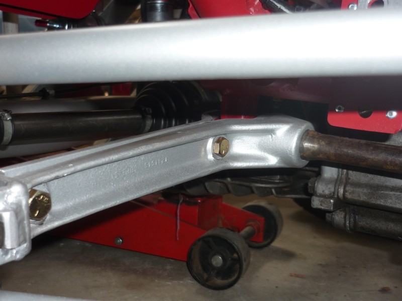
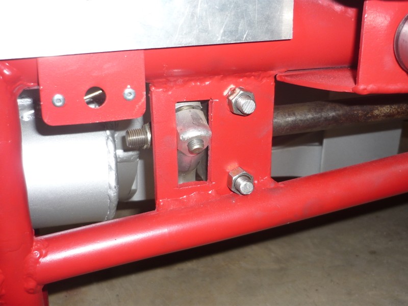
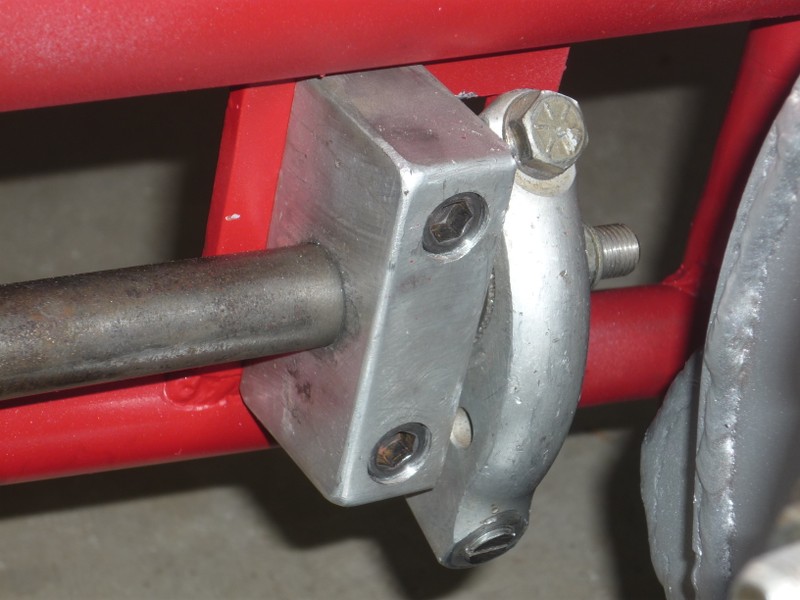
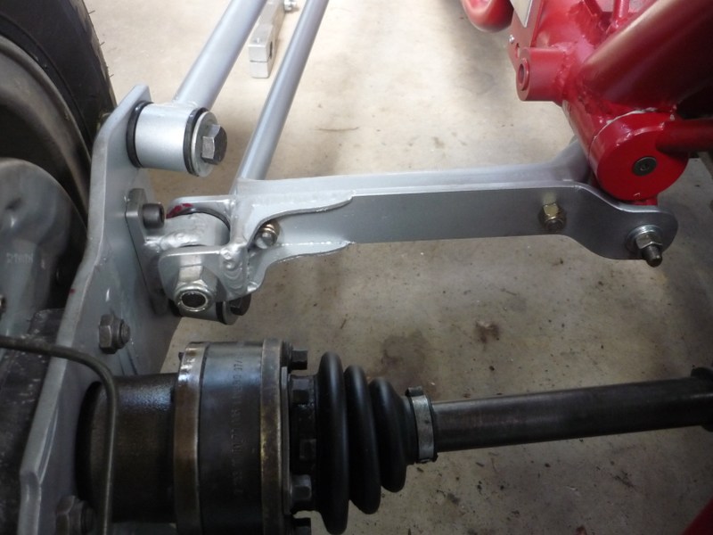
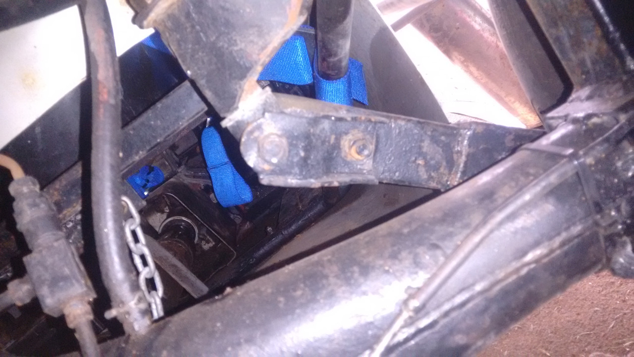
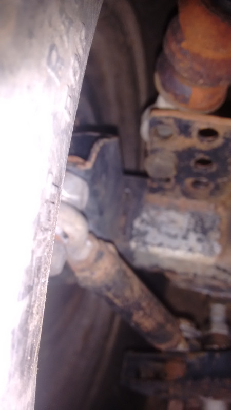
My pics show the Landcruiser IFS version which has the splined bracket bolted to lower wishbone and the other end of the bar with the adjuster. Pic 3-4
The other pics show how this can be adapted into a longitudional rear torsion bar setup for speedway. In this case of my 49y/o Speedway Supermodified using what was then industry standard on many midgets and SuperMods. Using Morris Minor front torsion bars mounted inside the chassis with the front of the bar mounted to the chassis with the stop/ ride height adjuster facing down. Pic 2 and 4.The next pic shows the rear end of the bar with the modified Morris torsion arm facing down at about 45 degrees Pic 5 where it then has a pullrod up to the front of the diff tube. Pic 5
The vast majority of modern Speedway F500, Midget and Sprintcar use what is known as cross bar.
The front and rear of the chassis has two torsion tubes full width of the chassis. The adjuster/ stop for set up is on the opposite end to the arms, at least a foot long that simply slide on the axle. Pic1
Because of the scale of production these are all quite cheap parts. Torsion bars are generally gun drilled and come in a range of lengths and rate
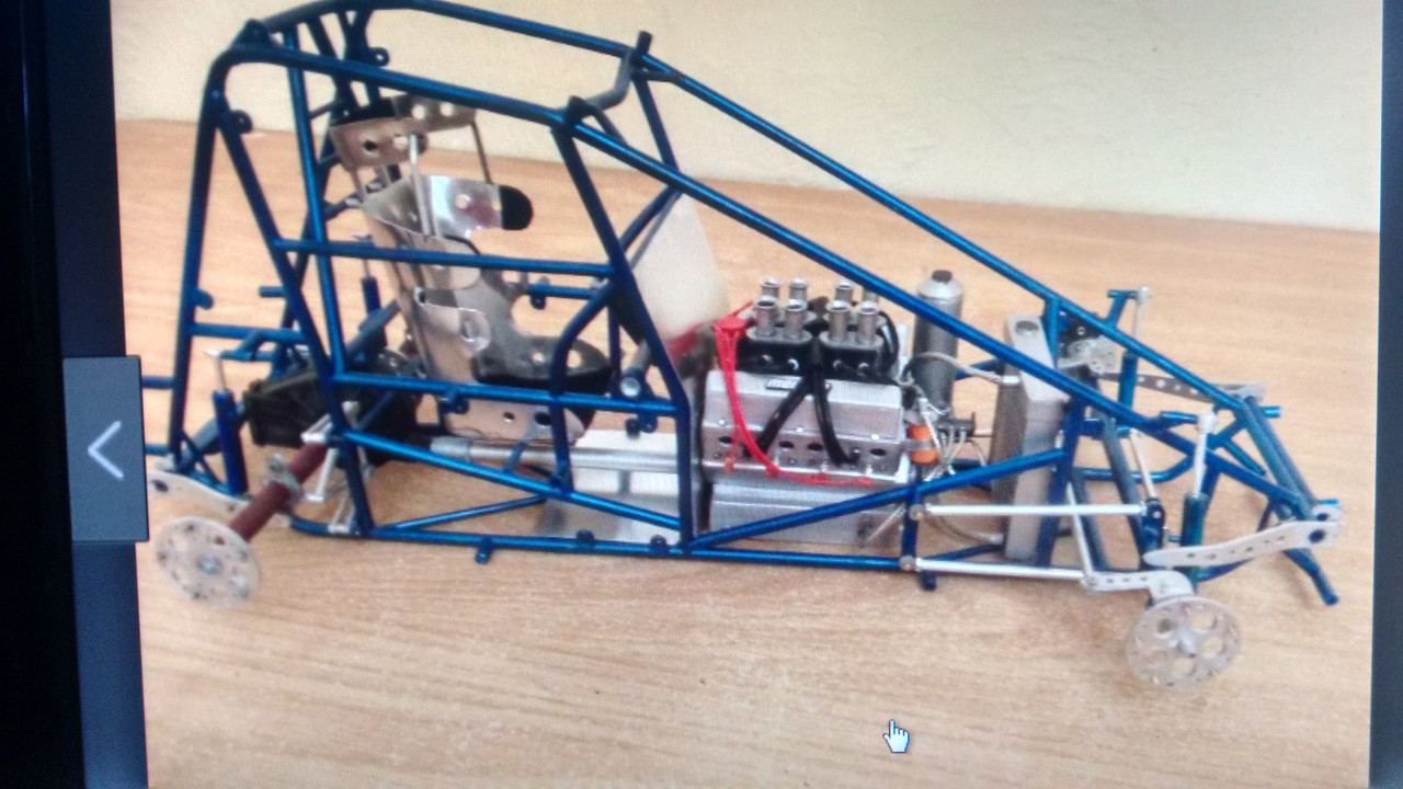
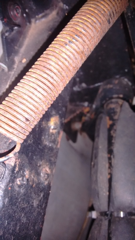
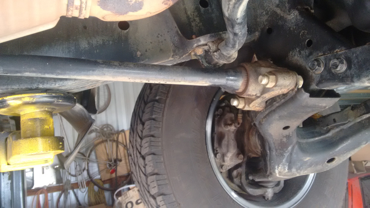
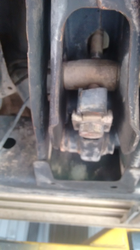
#23

Posted 07 December 2017 - 18:23
As a result I am also now shown as the progenitor of the thread, not Nathan (who is keeping suspiciously quiet!) and am suffering the shame of being a torsion bar ignoramus. I may never be able to show my face here again. So it's not all bad......
My apologies!! I'm horrible for asking a question and not confirming I understand the answer! But if I recall, I went looking for Lotus 72 pictures, and actually found a large scale model to help paint the picture.
#24

Posted 08 December 2017 - 02:00
OK, the suspension architecture, 2 body mounts with trailing arms and a torsion/bending element linking them, is a twist beam. Whether the torsion element is beam or a bar depends on the manufacturer (some use both in the same suspension). The torsion element operates as an ARB not as a road spring.
hmm,
there are 3 torsion bars.. 2 are fixed to the suspension mounts and are independent of each other, each serve as a separate spring for each wheel.... in the middle of the black tube there is a third one that serves as an ARB... I dont see the why this would be a twist beam instead od torsion bar setup..

Edited by kikiturbo2, 08 December 2017 - 02:11.
#25

Posted 08 December 2017 - 02:55
Ha, OK, yes that's got torsion road springs Neat
#26

Posted 08 December 2017 - 11:51
" I want to be able to set it up accurately and quickly in a ploughed field" - a nice challenge for a junior race engineer!
![]()
![]()
Wow, incredible.
#27

Posted 10 December 2017 - 05:20
The 72 used compound torsion bars where one , solid , bar is inside an outer , tubular, bar. This halved the length of the bars and means the end support can be very light as the heavy, localised , twisting forces Greg mentions are all in the suspension end. It requires rifle drilling the outer bar and precision splining all of which Lotus did at horrendous cost.
Panhard did a similar thing with three torsion bars but used simple bars linked by a sort of steel doughnut at the inner end.
Mind you, the 72 did win a lot of races so on that basis well worthwhile. I believe Classic Team Lotus still has a large stock of the original bars as getting new ones made is mega expensive.
The torsion bars made the 72 hard to set up as did the rising rate linkages which pulled on the bars. It was the desire for rising rate which helped decide to use torsion bars. IIRC Lotus developed the first fully independent set up platforms to use in-field to get all the ride height, bar rate and linkage angle of attack correct. Chapman's instruction was " I want to be able to set it up accurately and quickly in a ploughed field" - a nice challenge for a junior race engineer!
BTW one benefit of using torsion bars in the layout described by Greg is that a simple electric motor and screw jack system can provide load levelling - as used by Packard. Simpler than air bags and compressors and more fail safe .
The ploughed field bit must mean Chapman was wanting to go dirt oval racing! Some of the tracks are more like a cowpaddock!
#28

Posted 11 December 2017 - 19:53
My apologies!! I'm horrible for asking a question and not confirming I understand the answer! But if I recall, I went looking for Lotus 72 pictures, and actually found a large scale model to help paint the picture.
I hadn't noticed the year 2000 date! Nathan, did you really start this thread 17 years ago? And what a coincidence it would reappear exactly a week or two after I worked on my stepson's truck with a torsion bar suspension.
#29

Posted 12 December 2017 - 22:53
I did ![]() I was a bean sprout back then.
I was a bean sprout back then.
#30

Posted 17 December 2017 - 19:34
One special case of the torsion bar spring seems to have fallen out of favour - the Z bar.
Basically it’s an anti roll bar but with the ends pointing in opposite direction instead of the same way as for a normal anti roll bar.
Obviously both are torsion springs even if they are often hollow to save weight. With an AR and Z bar set up all the roll stiffness comes from the AR bar with none from the Z bar and all double wheel bump comes from the Z bar with single wheel bump from both.
The idea being that, broadly, you can tune for bump and roll stiffness in isolation. If you get really clever and put a third spring element in the middle of the AR bar you can control all three motions, bump, roll and heave almost independently.
A lot of FVee cars use a Z bar at the rear to minimize roll stiffness on the swing axle set up.
Porsche used a Z bar on the front of its 910 bergspyder hillclimb car in the 1960's This was partially to help with the problem of very low front weight on that car and also as part of the weight saving (!). The car had a 2.2 litre engine but weighed only 382kg.
A later development saved even more weight by replacing he fuel pump with a fuel sphere pressurized to 215 psi . Very light but maybe not to safe in a crash!
#31

Posted 19 December 2017 - 02:23
Another good feature of torsion bar suspension is that the "spring" does not contribute to unsprung weight, whereas with a typical coil spring between 30 to 50% of the springs weight is allocated to the wheel end. Of course, the suspension spring arm is likely to be a bit more robust than an arm that is not serving the dual purpose of wheel location and load carrying, as should be apparent from this graphic of the front suspension of the ~1950 Jowett Jupiter:

#32

Posted 19 December 2017 - 03:57
Hmm, you still get the referred inertia from the torsion bar. And you are assuming that unsprung mass is bad. That's one of those old rules of thumb that kind of collapsed when investigated - there is an optimum for a given sprung mass and tire rate, but it isn't zero, and it is more than you might think. 50% of 4 kg of coil spring is neither here nor there in a modern suspension
#33

Posted 20 December 2017 - 05:04
Remember the transverse torsion spring arrangement used on some VW Beetle front suspensions, that was made from a stack of rectangular section steel bars?

#34

Posted 20 December 2017 - 22:48
Did they bother with dampers?
#35

Posted 25 December 2017 - 09:24
Did they bother with dampers?
Thats what those big towers on the front of a Vee is. Shock Towers.
And having once owned a basic shortened floor pan VW buggy when you break a front shock it is as near as undriveable as doing so with a coil spring. And yes I was surprised. And it had had a couple of leaves removed as well.
I have had the misfortune over the years to have driven that buggy, an early Holden with a broken front shock and a broken rear shock and recently my Supermodified with a broken l/r shock on a torsion bar set up. The VW was hopeless and returned very slowly to the trailer, the Holden front coil was dangerous and was too driven very slowly to be replaced, rear shock with leaves was a bit bouncy but driveable and the Supermod was very how ya going. Though the track was that rough I was unsure and coasted around at the rear of the field. And was lucky to borrow a spare from another competitor and it was so much better! Though with the broken shock it was driveable whereas the VW front one was terrible. It says a lot about a beam axle being easier to damp than an independent set up. probably the only real advantage. Maybe why all the open wheel classes are beam axle.
#36

Posted 27 May 2019 - 11:19
Finding the revived discussion on an old thread, I thought I'd inquire here.
For a model I'm working on, I'm looking for pictures of the brackets on the Lotus 72 on the ends of the torsion bars to the linkage rods to the front wishbones and rear camber adjusters. I've turned the web upside down trying to find pics but, so far, without success. Any help or pointers would be very welcome. Thank you.
#37

Posted 27 May 2019 - 12:27
Finding the revived discussion on an old thread, I thought I'd inquire here.
For a model I'm working on, I'm looking for pictures of the brackets on the Lotus 72 on the ends of the torsion bars to the linkage rods to the front wishbones and rear camber adjusters. I've turned the web upside down trying to find pics but, so far, without success. Any help or pointers would be very welcome. Thank you.
The May/June issue of Vintage Motorsports has a Lotus 72 article with two close up suspension photos.
#38

Posted 27 May 2019 - 22:43
I think I have posted this diagram before but this thread is a chance to show one of my favourite 1950's suspension layouts again.
It is interconnected like a 2CV or BMC 1100 and has self levelling too.
As the torsion bars run from the front axle lever arm to the rear ones there are no twisting loads on the chassis.
http://www.1956packa...rsionLevel.html
There are some elements of a modern anti pitch F! suspension in there I think.
I suspect that suspension would have been dangerously awful when braking or accelerating on uneven surfaces.
Given that it had no pitch control other than load leveling, which reacted in 7-10 seconds, the normal pitch from accel and brake would have been controlled by the anti-dive and anti-squat suspension geometry, which I understand has the effect of severely stiffening and nearly locking up the suspension under those conditions.
Hate to see good but ultimately failed ideas romanticized just because they're from some nostalgic auto era.
#39

Posted 28 May 2019 - 17:38
"the normal pitch from accel and brake would have been controlled by the anti-dive and anti-squat suspension geometry, which I understand has the effect of severely stiffening and nearly locking up the suspension under those conditions.
"
Sounds like something I might have said, but thinking about it, done with care, there's no reason why antidive and antisquat HAVE to lock the suspension up any more than GRCH locks the car up in roll. It is the same physics. In the article they say it works well so long as the shocks are good. Now, in the context of 1950s-60s American barges quite what they mean by 'well' is open for discussion, but using shocks to make up for springing problems is by no means a dead art even now.
Advertisement
#40

Posted 29 May 2019 - 01:12
I guess it's all a matter of degree, as always. With a suspension that would seem to provide inherently soft control in pitch relative to normal designs, the difference would have to be made up with anti-squat and/or anti-dive, otherwise just live with a lot of pitching motion.
This corresponds to the mechanics in roll as you say, in that a car with very soft roll resistance might be stiffened with higher roll centers, but to the detriment of handling.
#41

Posted 29 May 2019 - 21:33
The reason high anti geometries appear to lock the suspension is that you are passing a lot more force through the links and therefore the joint friction forces are higher.
It doesn't make the suspension stiffer in a spring sense, but it does increase the vertical hysteresis a lot which is like fitting a super stiff damper.
#42

Posted 08 June 2019 - 16:26
#43

Posted 14 June 2019 - 12:00
"the normal pitch from accel and brake would have been controlled by the anti-dive and anti-squat suspension geometry, which I understand has the effect of severely stiffening and nearly locking up the suspension under those conditions.
"
Sounds like something I might have said, but thinking about it, done with care, there's no reason why antidive and antisquat HAVE to lock the suspension up any more than GRCH locks the car up in roll. It is the same physics. In the article they say it works well so long as the shocks are good. Now, in the context of 1950s-60s American barges quite what they mean by 'well' is open for discussion, but using shocks to make up for springing problems is by no means a dead art even now.
What sort of springing problem would/could not be rectified in the production line Greg? Or it fiddling the dampers a quicker fix?
#44

Posted 17 June 2019 - 06:59
Usually the ride guys specify what corner frequencies we want, to give a good ride. This is based on that flat ride criterion. Then the geniusses in marketing tell us what GVW they want. Springs are designed to suit and the rest of the car is designed around them (well, sort of). Then rather later in the day (about 2 years later) we actually get the likely build weights. Then marketing panic because the payload is non competitive so they up GVW again (putting the frighteners on the brakes guys). So we need new springs to meet the ride targets. but now we've run out of room for the springs, because they are bigger to support the extra weight, so unless CAD redraw the body (resetting that 2 years) then we have to start compromising. The meat in this particular sandwich are the ride guys, at the cost of making our life more difficult we can keep everybody else happy. So we compensate for non perfect corner frequencies (which were a stab in the dark anyway) by changing the shock tune.
There are many variations on that theme, with the result that shocks are being retuned right up until Job 1.
Edited by Greg Locock, 17 June 2019 - 07:07.
#45

Posted 17 June 2019 - 22:01
Hi Greg. I have a car with adjustable dampers all round. Single external adjuster, easily accessible, adjusts bump and rebound. Is there a simple process to follow to tune these for a) ride/handling compromise for everyday driving and b) handling - eg a track day.
#46

Posted 17 June 2019 - 22:51
I don't, and I'd have thought Tim would be much more helpful than me on the track stuff, but as a first question what exactly can you adjust? Did they include graphs? Once upon a time John Miles measured the front shocks on a whole bunch of B class cars (Fiesta etc). He then overlaid the graphs after scaling them for motion ratio. If you crudely linearise the curve as a low speed bit and then a high speed compression and high speed rebound, he found that the ratio of the two high speed parts varied wildly from about equal, to 4 times as much rebound as compression. His private conclusion was that nobody in the 90s really knew what they were doing, in the paper he wrote he just said that shock tuning is a difficult compromise, assuming that all the development engineers were competent.
Milliken includes a brief section on dampers for racecars, I don't have it to hand but I can dig that out.
The way we do it now for road cars is to use a 'simple' 4 dof sideview model running over a variety of road surfaces. Then a whole bunch of rules of thumb are used to generate a good shock curve. This seems to result in a tune that is good enough as a starting point, but I'm not convinced it is a whole lot better than just using the tune from the last production model as a baseline. Up until recently we couldn't correlate primary ride between ADAMS and the real world, a few years back I had a two month slot to investigate it and was able to match 4 out of 6 of our metrics, and identify why the one of the others was being measured wrong.
#47

Posted 18 June 2019 - 19:15
I've never read a really good book on dampers and damping of racecars. Jan Zuijdijk (of JRZ fame) has a book that he put out through Race Tech Magazine. It's garbage, and that's a shame, because I'd really like to know what he thinks. It never gets there.
I can come up with spring rates and damper curves for any given car I happen to be working. I've got general rules of thumb and 'magic number' calculations which get me there. None of it is a first principles approach, though, so it's tough to really trust what I'm doing. It's more of a thing where it seems to work, but I'm curious at what point it won't.
15-20 years ago I had an email exchange with John Dixon, who wrote _The Shock Absorber Handbook_. At the time, he had very little to do with racing dampers and little, it seems, with real dampers at all. He knew about them philosophically a lot more than he knew about them in a practical sense. There are a couple other newer books out that I'm interested in reading, but I think this is probably one of those situations where it's very difficult to produce a definitive answer.
I try to keep a transmissibility curve in my head when I'm interpreting driver comments. We want the chassis to have perfect transmissibility of low frequency inputs(road and driver) and we want it to limit the transmissibility of high frequency road inputs. Of course, we don't look usually look at damper curves w.r.t. frequency. We plot damper forces w.r.t. shaft speed (time). Also, the adjustments we make to the dampers (bleed and shim stack preloads, mostly) translate to changing the damper forces w.r.t. shaft speed. The mechanical system doesn't care about the time domain, it's all resolved in the frequency domain. When damper shaft speeds and frequencies are both 'low' or 'high', then it's easy to see what change is in order. When they're mixed (e.g. low frequency w/ high damper shaft speeds or vice-versa) things can get confusing quickly.
#48

Posted 20 June 2019 - 18:30
C'mon, Greg. You're supposed to tell me what I'm missing!
I will say, I've done some damper testing recently which was pretty impressive. I have an old Toyota Tacoma truck. I've had some sort of Monroe (whatever 'best' model) damper on the thing for the last 15 years. I just stuck some Bilstein's on it. I should have done that 15 years ago. They're so much better than the previous dampers that it's absurd. All of the sudden I can go over bumps without jumping all around and I can actually induce a little understeer if I want (I like U/S). God forbid!
Edited by Fat Boy, 20 June 2019 - 18:31.
#49

Posted 03 July 2019 - 03:23
That conclusion rests on the assumption that Bilstein shocks from 15 years ago were as good as they are now, AND that the 15 year old Monroes didn't degrade over time. Neither is likely.
#50

Posted 03 July 2019 - 05:04
just guessing here, but I wonder if the relativities between Monroe and Bilstein would have (not) appreciably changed over the period?


