
0.6 Module gear profile
#1

Posted 22 August 2012 - 13:14
I have fund enought to make some of the common sizes but i need the profile.
Advertisement
#2

Posted 22 August 2012 - 13:15
Trying to find a drawing of 0.6 module teeth but can`t find it. Does anyone know about a trick page who got this?
I have fund enought to make some of the common sizes but i need the profile.

#3

Posted 22 August 2012 - 14:28
#4

Posted 23 August 2012 - 08:34
Try Davall Gears or http://www.muffettgears.co.uk/ they may have profiles in their tech info, design info here
Thanks they got the math covered but not the profile shape.
Edited by MatsNorway, 23 August 2012 - 08:34.
#5

Posted 23 August 2012 - 11:32
The gearwheel in the photo has 66 teeth with 0.6 module.
If you “zoom-in” at “60%” the profile of another gearwheel having 1.0 module and 66 teeth, you take the profile of the 0.6 module / 66 teeth gearwheel.
Manolis Pattakos
#7

Posted 23 August 2012 - 23:41
There is a script for Rhino that will generate the profiles. If you don't have Rhino you can get a free trial at www.rhino3d.com.
#8

Posted 24 August 2012 - 20:01
Have a look here: http://www.rayflecta...pts-Gallery.htm
There is a script for Rhino that will generate the profiles. If you don't have Rhino you can get a free trial at www.rhino3d.com.
Good thinking Batman! Rhino, my favourite solid modelling program - Does it work with Rhino 3?
#9

Posted 24 August 2012 - 22:39
20050207 or higher for Rhino V3
20060906 or higher for Rhino V4
Installation:
See bottom of this page.
Suggested Alias:
GearGen
EDIT: BTW, it's free.
Edited by saudoso, 24 August 2012 - 22:42.
#10

Posted 25 August 2012 - 06:09

The cutting tool (red ruler) has "trapezoidal" teeth.
The "pitch circle" of the gearwheel to be formed "rolls" (without sliding) on the "center line" along the teeth of the "cutting ruler".
The angle between the two sides of a trapezoidal tooth is, typically, 40 degrees.
The "step" or offset between successive trapezoidal teeth equals to the module times pi (module*pi).
0.6 module means that the cutting tool is formed by putting the next "trapezoidal" tooth at 0.6*pi=1.885mm offset.
The cutting tool that creates gearwheels of module 1.0 has the same shape (but it's bigger) with the cutting tool that creates gearwheels of module 0.6. This is why the number of teeth of a gearwheel defines the shape of the tooth, no matter what the module is.
The blue gear in the above animation has only 12 teeth and shows that below a number of teeth, the cutting tool cuts some material at the base of each tooth.
In the animation below the 12 teeth gearwheel (blue) of the above animation cooperates with the red gearwheel (12 teeth, same module).

Thanks
Manolis Pattakos
#11

Posted 26 August 2012 - 13:47
The animation below shows the principle the typical gearwheels are formed:
The cutting tool (red ruler) has "trapezoidal" teeth.
The "pitch circle" of the gearwheel to be formed "rolls" (without sliding) on the "center line" along the teeth of the "cutting ruler".
The angle between the two sides of a trapezoidal tooth is, typically, 40 degrees.
The "step" or offset between successive trapezoidal teeth equals to the module times pi (module*pi).
0.6 module means that the cutting tool is formed by putting the next "trapezoidal" tooth at 0.6*pi=1.885mm offset.
The cutting tool that creates gearwheels of module 1.0 has the same shape (but it's bigger) with the cutting tool that creates gearwheels of module 0.6. This is why the number of teeth of a gearwheel defines the shape of the tooth, no matter what the module is.
Are you sure about that?
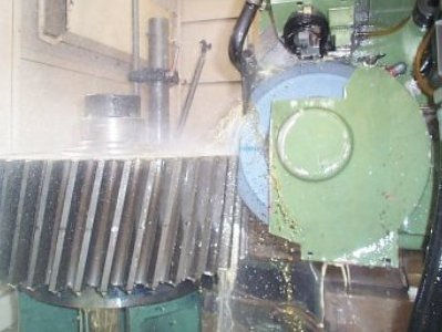
I thought they were formed used gear cutters or gear hobs.


Or grinding
#12

Posted 26 August 2012 - 16:11
http://www.sdp-si.co...805cat.htm#tech
Stock Drive Products just makes little gears but the equations still apply, plug in your module number and number of teeth .
#13

Posted 26 August 2012 - 18:09
Are you sure about that?
I thought they were formed used gear cutters or gear hobs.
The geometry described is perfectly correct.
It is the basic theory for the typical gearwheels.
Similar – but a little more complex - is the theory for the bevel gears.
When something can be described geometrically as completely and precisely as the gearwheels, the cutting tools, and the machinery used to manufacture them, has just to replicate, as precisely as possible, the geometry.
Each of the disk-shape gear-cutters of your post:

can cut precisely only one specific gearwheel, say 15 teeth with 2 module; if the same disk-gear-cutter is used to cut a 17 teeth / 2 module gearwheel, the result is not correct (more noise, less reliability, lower efficiency). Actually it is a compromise between precision and cost.
But the worm-shape gear-cutter:

is the perfect tool. If the axial “step” (worm pitch) of the worm-shape cutting tool is 2*pi mm (6.28… mm), then the worm-shape gear-cutter is for cutting gearwheels having module 2 and any number of teeth like 12, like 50, like 140 etc, all with the correct tooth-shape. With the same tool you can make helical gears, as well.
If you look at the worm-shape gear-cutter photo above, you can see that the “cutting edge” of the worm-shape cutting tool is nothing but the red “cutting ruler” shown in my animation. And as you rotate the worm-shape cutting-tool, the cutting edge proceeds axially, just like the red “cutting ruler” proceed horizontally.
Theory and practice agree.
MatsNorway, If you need the tooth-shape for a specific number of teeth (no matter what the module is), give me the teeth number.
Thanks
Manolis Pattakos
#14

Posted 30 August 2012 - 18:38
Current design is undetermined. That said i think in the ball park is more than enough. Spur gears got a efficiency at 98-99% i can live with 98%
But i think i will have a go at a diff with teeth count: 39
#15

Posted 31 August 2012 - 08:29
How many times can i ask?
Current design is undetermined. That said i think in the ball park is more than enough. Spur gears got a efficiency at 98-99% i can live with 98%
But i think i will have a go at a diff with teeth count: 39
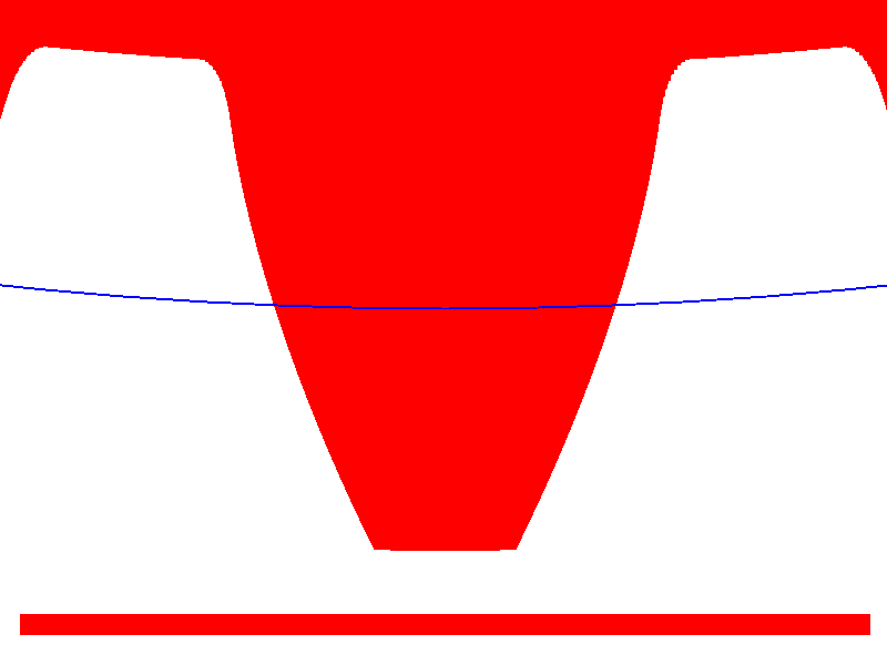
Here is the form of the tooth of a gearwheel with 39 teeth.
The blue line is the pitch circle.
The long side of the red rectangle equals to one tenth of the pitch circle diameter (in case you try to locate the center of the gear).
Click here for the same drawing bigger.
Manolis Pattakos
#16

Posted 03 September 2012 - 04:18
The animation below shows the principle the typical gearwheels are formed:
The cutting tool (red ruler) has "trapezoidal" teeth.
The "pitch circle" of the gearwheel to be formed "rolls" (without sliding) on the "center line" along the teeth of the "cutting ruler".
The angle between the two sides of a trapezoidal tooth is, typically, 40 degrees.
The "step" or offset between successive trapezoidal teeth equals to the module times pi (module*pi).
0.6 module means that the cutting tool is formed by putting the next "trapezoidal" tooth at 0.6*pi=1.885mm offset.
The cutting tool that creates gearwheels of module 1.0 has the same shape (but it's bigger) with the cutting tool that creates gearwheels of module 0.6. This is why the number of teeth of a gearwheel defines the shape of the tooth, no matter what the module is.
The blue gear in the above animation has only 12 teeth and shows that below a number of teeth, the cutting tool cuts some material at the base of each tooth.
In the animation below the 12 teeth gearwheel (blue) of the above animation cooperates with the red gearwheel (12 teeth, same module).
Thanks
Manolis Pattakos
Manolis,
The 12T blue gear definitely shows some undercutting below the pitch line. This type of situation is usually not acceptable. However it can usually be corrected with profile shift and/or an increase in pressure angle.
The 39T red gear profile in the later post also wold benefit from a larger root fillet radius and some profile tip relief.
Regards,
slider
#17

Posted 05 September 2012 - 03:09
Manolis,
The 12T blue gear definitely shows some undercutting below the pitch line. This type of situation is usually not acceptable. However it can usually be corrected with profile shift and/or an increase in pressure angle.
The 39T red gear profile in the later post also wold benefit from a larger root fillet radius and some profile tip relief.
Regards,
slider
Slider,
you are right:
"The 12T blue gear definitely shows some undercutting below the pitch line. This type of situation is usually not acceptable. However it can usually be corrected with profile shift and/or an increase in pressure angle. "
but the correction is a compromise with its own problems.
Another solution when using gearwheels having small numbers of teeth is the "expensive" epicycloid gearing (with the CNC machines it is not expensive, any longer), used in the Roots compressors (it works even with two teeth), in the oil pumps:
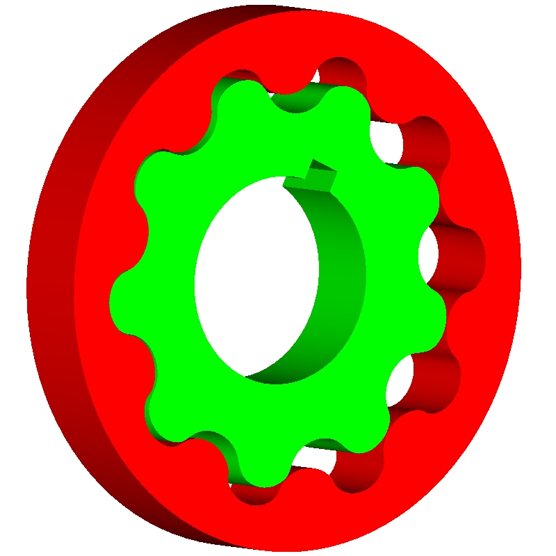
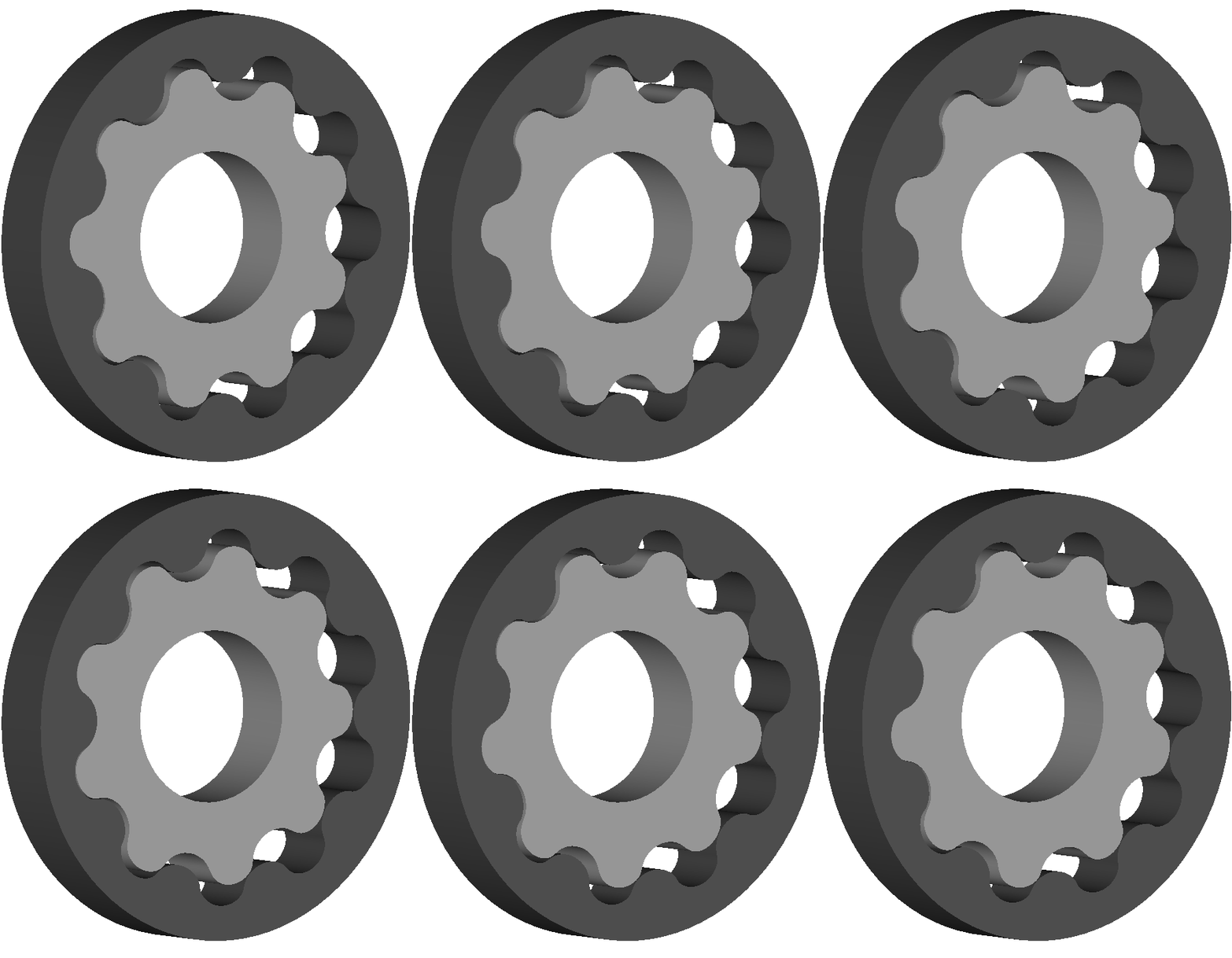
like that made and used for the PatOP engine, in the clocks etc.
Thanks
Manolis Pattakos
Edited by manolis, 05 September 2012 - 13:38.
#18

Posted 06 September 2012 - 03:43
Manolis,
Yes, compromise is the problem with everything in engineering. But I'd still prefer an adjustment in pressure angle or profile shift as opposed to epicycloid gear tooth geometries.
Regards,
slider
#19

Posted 07 September 2012 - 02:52
"...but the correction is a compromise with its own problems. ..."
Manolis,
Yes, compromise is the problem with everything in engineering. But I'd still prefer an adjustment in pressure angle or profile shift as opposed to epicycloid gear tooth geometries.
Regards,
slider
Slider, the idea was to show - with the oportuntity of MatsNorway question - how simple and general is the theory behind the typical gearwheels, and that there are alternatives.
Someone may learned / realized something he didn't know / think before.
When this theory gets to its limits, gears like:
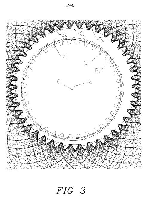
can be made, by which the inertia torque of an even-firing 4-stroke four-cylinder can be "filtered" in the primary transmission and never arrive to the clutch, to the gearbox and to the drive wheel of a bike.
Thanks
Manolis Pattakos
Advertisement
#20

Posted 07 September 2012 - 16:51
A beautiful image - it looks a bit like an M C Escher drawing, but with purpose.
#21

Posted 08 September 2012 - 01:12
Slider, the idea was to show - with the oportuntity of MatsNorway question - how simple and general is the theory behind the typical gearwheels, and that there are alternatives.
Someone may learned / realized something he didn't know / think before.
Thanks
Manolis Pattakos
manolis,
Yes, there are definitely lots of alternatives to the common involute gear tooth geometry. With the advent of powerful digital computers, sophisticated CAD/FEA softwares, and multi-axis CNC machine tools, the spectrum of gear geometries it is now possible to design, analyze and manufacture is virtually limitless. However, I would not agree that the mathematics required for accurately defining non-standard, optimized, high-performance gear topologies is "simple".
Your example of a simple 2D involute spur gear profile is a good example. The standard "simple" 2D ruled involute geometry produces a tooth with undercutting and a less than optimum root fillet shape. The mathematics required for a more optimized 3D tooth shape with profile shift/tip relief/elliptical root fillet/modified addendum/lead correction/face crown/etc. is far more complex.
Having said all that, I truly appreciate your sense of creativity and the great effort you put into your posts.
Best regards,
slider


