More Oddball Engines
#1
Posted 20 April 2000 - 11:40
This is a cam-type engine that is quite similar to the almost practical Fairchild-Caminez engine which was actually certified as an aircraft engine, but this ones uses rockers between the pistons and the central two-lobe cam whereas the F-C engine had large roller bearings at the base of the pistons riding on the central cam. I'll have to find a picture of that one. Words are often inadequate to describe some of these oddities.
Advertisement
#2
Posted 20 April 2000 - 18:59
I have several books on unusual engines.
anyway have a look at mine http://www.sixstroke.com
malbeare
#3
Posted 21 April 2000 - 08:14
------------------
Life and love are mixed with pain...
#4
Posted 21 April 2000 - 11:53
Stop me before I hurt someone!
#5
Posted 21 April 2000 - 13:04
A suggestion - let's post one oddball engine on a Friday and discuss it for the week.
Post under "Oddball No 3" or whatever.
That way we will think and comment a little deeper on the weeks posting - while drooling a little with the approach of Friday, in expectation of a new "fix"
Good Man Go.
#6
Posted 21 April 2000 - 13:39
I saw you posted over in the mosh pit (Readers' Comments). You want us to think you're an old fart, but you admitted there you're only 66. I nearly got my ass kicked at a tennis tournament last summer by a guy that was 10 years older than you!
Edi,
That isn't a bad idea. Being a flaky artist though, I'm not much on schedules.
#7
Posted 24 April 2000 - 10:41
Dear Ray,Originally posted by Ray Bell:
Yeah, yeah, yeah, that's how the Commer double knocker worked! How about a diagram?
It is nothing like a Commer knocker. My engine opperates on the 4stroke principle and is naturally aspirated. It has 2 crankshafts one driving at half speed through a scotch yoke with a much shorter stroke.
Malbeare http://www.sixstroke.com
If somebody knows how to insert diagrams or pictures please tell me
malbeare@terra.net.au
Thankyou
#8
Posted 24 April 2000 - 14:58
Regards,
Kurt
#9
Posted 24 April 2000 - 15:02
Price: $9,750.00
- 1.00" bore .970 stroke (total displacement 7.678 c.i.)
- Estimated horsepower 7.0 @ 9,500 r.p.m.
- Firing order 1, 1O, 9, 4, 3, 6, 5, 8, 7, 2
- Electronic Ignition
- Pressure lubrication
- Four bolt (investment cast Beryllium alloy) main caps
- Investment cast (stainless steel) crankshaft
- Throttle body fuel injection
- Centrifigual Clutch
- Transmission- forward, neutral, reverse
- Connecting rods (investment cast Beryllium alloy)
- Cast iron cylinder liners
- Custom ground billet camshaft
- High efficiency centrifugal water pump
www.viper-v10.com
#10
Posted 26 April 2000 - 04:16
#11
Posted 27 April 2000 - 12:35
------------------
Life and love are mixed with pain...
#12
Posted 27 April 2000 - 13:54
I really had to dig for this one, but finally here it is, the Commer Double Knocker:
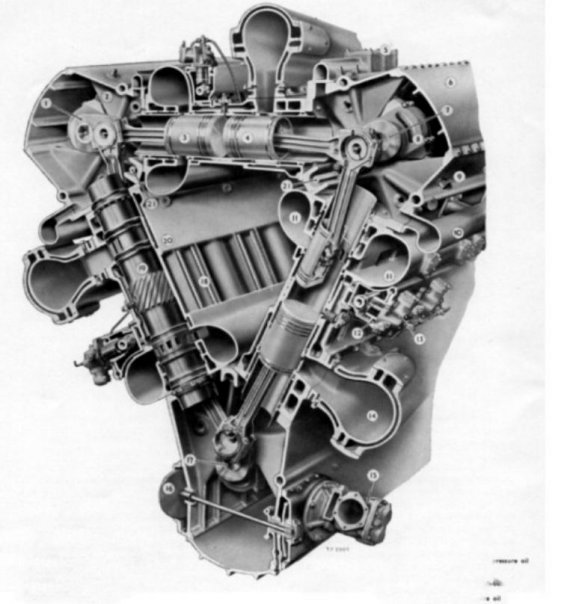
Commer TS3 Two Stroke Diesel Engine
Have you got it yet? The engine has three cylinders situated above and across the plane of the
crankshaft. Each cylinder contains two pistons with the crown facing inwards. On each side the
pistons are linked to the crankshaft via a short connecting rod, a substantial rocker arm and a
secondary connecting rod. Unlike a petrol engine, a two stroke diesel cannot use crankcase pressure
to boost the air supply, because it would tend to combust any oil that was entrapped in the air. A
Roots blower (i.e. rotating lobe type) is situated on the front of the engine and supplies the
combustion air. The total displacement is only 3.25 litres, but the engine develops 90 B.H.P.
Contemporary four stroke engines, for example the Gardner 5LW produced this kind of power
from 8 litres. The engine was introduced in 1954 and power outputs were progressively increased.
The engine was discontinued when the Rootes Group was taken over by Chrysler in 1968. At the
time a four cylinder prototype version was under test and this never made it to production. An
example of the TS4 can be seen in the Leyland Historic Commercial Museum in Lancashire,
England.
I think Art would've appreciated this one.
#13
Posted 27 April 2000 - 14:17
Quite clever, really, the way the porting enabled a good scavenge and fill of the cylinders... but who would want to be one of those rockers?
They had five and six speed gearboxes which also bolted straight onto the Humber engines of the day, according to Steve Dixon, who was foolish enough to play with the Humbers. Humber engines were the alternative for those not wanting to pay so much for the trucks. The 4-cyl Humber engine was the Sunbeam Talbot engine, with nice long conrods made out of duralumin... you know, like the motorcycle rods the poms made in that era.
------------------
Life and love are mixed with pain...
[This message has been edited by Ray Bell (edited 04-27-2000).]
#14
Posted 27 April 2000 - 14:23
Practical, too, no head gaskets to blow, no need to dismantle the crank to get at the pistons...
Where do you get these things, desmo?
------------------
Life and love are mixed with pain...
[This message has been edited by Ray Bell (edited 04-27-2000).]
#15
Posted 29 April 2000 - 11:08
SOME UNUSUAL ENGINES by L J K SETRIGHT published by mechanical engineering publications ltd for the Institution of Mechanical Engineers London
A history of AIRCRAFT PISTON ENGINES by HERSCHEL SMITH published by Sunflower University Press.
My scanner is on the blink and I still connot insert pictures Never mind I will learn one day.
Malbeare http://www.sixstroke.com
#16
Posted 01 May 2000 - 01:10
The cylinder block turns with the crankshaft, I don't know actually how it works but you can visit his site http://www.interplan...usuarios/rotary
[This message has been edited by Elio (edited 04-30-2000).]
#17
Posted 01 May 2000 - 17:47
------------------
Life and love are mixed with pain...
#18
Posted 02 May 2000 - 15:54
Just scimmed through the site and found one of the funniest remarks about an engine ever:
'Consumption: Not tested but very low'
Johan V.
#19
Posted 02 May 2000 - 15:57
Try selecting the text with your mouse. The text turns blue on a white background.
Johan V.
Advertisement
#20
Posted 07 May 2000 - 11:29
#21
Posted 09 July 2000 - 09:31
#22
Posted 09 July 2000 - 19:31
#23
Posted 09 July 2000 - 22:22
I've seen some odd ball engines, but I could never figure out Bristol T&C engine (I have cutaway drawing but can't post it even if I managed scaning it). It was 9 cylinder 7l engine of weird design and was used in Omnibuses. Can somebody enlighten me on the matter?
On the matter of strange valves- I like sliding cylinder sleeves engines (Willys-Knight), and radial engines with rotating set of heads (Sachsenberg, Soppit). Of course, those engines were produced before WWII.
#24
Posted 09 July 2000 - 22:27
#25
Posted 09 July 2000 - 23:59
I must read the wrong books... or not enough of them!
As for threads being deleted, des, that's been stopped now.
#26
Posted 10 July 2000 - 01:41
* Four-stroke, if you dare to belive it! My car has 660cc and the same power (1984).
The other type is known as Aspin valve (at least in german literature), since they employed it in their opposed 4 cylinder aircraft engines (1938- 1.7 litre, cca. 90HP @ 4500rpm). I was astounded when I consulted my 'Bible' and have read that principle has derived from engine by certain monsieur Cottereau exhibited on Paris Salon in 1910! The valve is conical, axis of cone being axis of cylinder. The valve itself has tubular shaped cut out- one end on the base of cone and other end on the side of cone (slightly curved hole). This is not very good description, but try to imagine a cone with torus segment subtraced (this will help if You are a bit mathematically versed), the centre of torus being in the same plane with cone base, and axis of torus also . The size of opening was cca 50% of cylinder bore. The valve rotated about its axis at half a crankshaft speed. The valve housing had two openings (for 4-stroke engines placed at somewhat less than 90°) and sparkplug mounted almost opposed to exhaust opening. The problem was, as I've mentioned before that side end of valve opening short-circuited exhaust and intake openings.
There is another type- Baer (1938). It differentiated from previous types in having two valves incorporated in one. It was by large similar to Brown type (as far as mounting and placment are concerned), bur cylinder head had two rectangular openings (exhaust and intake), and valve housing also. The valve had two rectangularly shaped openings rotated at cca 45° to each other, and rotated at quarter the speed of crankshaft. The testing on 1 liter Fiat 109A engine presented power increase (due to less power needed for valve operating, and due to greater achievable compression) fom cca 23HP to cca 32HP.
P.S. Finally one message that is longer than my signature.[p][Edited by Wolf on 07-10-2000]
#27
Posted 28 September 2000 - 19:36
#28
Posted 28 September 2000 - 21:04
Thanks old buddy!
If I'd have known about this thread I would have made more effort to connect up earlier this year. My favourite for wackiness is the 'Gnome et Rhone' monosoupape rotary aero engine. For those of you weak in the linguistics department 'monosoupape' has nothing to do with french onion soup! It means single valve, which again is misleading because it actually had 2 valves - it just had one in the head, while the other was in the crown of the piston. Meanwhile the whole gizmo rotated around a fixed crank! I once saw a cut-away example of one in a museum (but for the life of me can't remember where!).
The course of human endeavour to perfect the I.C engine never fails to amaze me. If the steam engine had had as many milions of man hours spent on it's development I wonder if we would all now be talking about Walford shuffle valves, and that?
#29
Posted 28 September 2000 - 22:40
#30
Posted 29 September 2000 - 05:51
Here's a relatively conventional approach. This is a Wooler motorcycle engine and would be considered a beam engine, a type more commonly seen in steam engines.
The engine (1926) was the feature of greatest interest and was laid out as a transverse-four, the cylinders on each side being one above the other. This alone was far from normal, but really unique was the way in which they were connected to the crankshaft, for this was based on the beam engine. Capacity was 500cc, and overhead valves were used.
The crankshaft ran along the machine, below all the cylinders, and was of a single-throw design. In fact, for the prototype, a modified assembly from a 150 cc New Imperial was used. Above the crankshaft was a T-shaped beam, which was pivoted at the junction of the leg and arms, this axis also Iying along the machine. A master con- necting rod joined the end of the T-leg to the crankshaft, so as this rotated, the beam oscillated. The arm of the T was set vertically, and each end was attached to two connecting rods, which pointed in opposite directions and ran out to the pistons. Thus, these moved in pairs, and the two pairs moved in opposition.
#31
Posted 29 September 2000 - 06:08
There is a company making running 1/4 scale replicas of this engine! See: http://www.replicaen...ducts/gnome.htm
#32
Posted 29 September 2000 - 12:17
I've seen that double knocker I.R.L. I first didn't understand how it worked. But an employee of the university explained it to me. (too bad all of the old engines are gone to a museum now)
#33
Posted 29 September 2000 - 13:26
I thought I read somewhere that they had at least tried to put one in an aircraft, not sure it worked out though...
Dave[p][Edited by bugeye on 09-29-2000]
#34
Posted 29 September 2000 - 23:10
W.R.T Gnome et Rhone Monosoupape
You keep beating me to it! Either you're getting way back on your schedules or you haven't got anything better to do!
There must be a better shot of it though, I see you can just make out the inlet valve imbedded in the piston crown (usually a sign off a disaster in any other motor!)
Now I've really got to dig deep to find something else (I suppose you've got info on the 'clap hands' engine from LJKS's SUE book?)
#35
Posted 02 October 2000 - 17:41
Mal, of six-stroke fame, was kind enough to email me this image showing the uncounted piston valve from the Gnome Monosoupape.
Mal,
I couldn't post the Bristol Hercules image, it was just too large a file size for a BB. Pity as it was an excellent illustration of how sleeve valves are run, which seems to be quite misunderstood. And the outside shot of the Monosoupape I didn't post because there are better images already up on the web and my server space is finite. Thanks for sending the image I posted though, I couldn't find one that good myself.
K
#36
Posted 03 October 2000 - 17:28
Would you consider the Wankel a contender?
Have a look at the OX2 engine: http://www.oxtwo.com/Profile.htm
IanC
#37
Posted 05 October 2000 - 20:06
#38
Posted 06 October 2000 - 00:40
#39
Posted 06 October 2000 - 01:09
This thread is holding on, isn't it.
Advertisement
#40
Posted 06 October 2000 - 02:14
#41
Posted 15 January 2001 - 09:39
#42
Posted 18 January 2001 - 04:01
#43
Posted 18 January 2001 - 07:13
The illustration I posted above is of a "top hat piston" design penned by Bernard Hooper for Norton-Villiers and was intended as a reply in the early 70s to the threat posed by the newly popular Japanese large-displacement motorcycles. The idea was to use the larger lower portion of each cylinder to charge it's neighbor rather than conventional crankcase charging. It was said to be considerably cleaner running than conventional two-stroke designs of the period. A proto was built by Norton and dubbed "Wulf", but of course by that point Norton was on it's deathbed and lacked the resources to see the idea through.
#44
Posted 19 January 2001 - 03:29
The one I described was a pommy design from the twenties.
#45
Posted 19 January 2001 - 08:00
Trojans of Croydon also built the Elva Courier, Mclarens of different spec and raced their own car,Formula 5000 and F1 driven by Tim Schenken and designed Ron Tauranac.
Jack
#48
Posted 07 September 2002 - 17:01
Originally posted by desmo
Here's quite an odd one that works something like a ball bearing set with an eliptic outer race. This one is sufficiently odd that I'll just refer you to the website for details on it's operation: www.ballpistonengine.com
I went to the website.
Theres something I'm seriously missing here, either I'm wrong or these Guys get my "Wally's' of the year award. (For you non Aussie's, a "Wally" is a thickhead!)
As an air pump I give this top marks, but as an engine these Guys are seriously self delusional.
How on earth do they think they are going to seal rotating balls against combustion leakage ??
How do they think they are going to lubricate those balls ??
Even if they manage to seal it with say some sort of ceramic concave ring around the ball, this would make the ball smaller than the bore making the stroke shorter and the ramp (ball tracks illustrated) angle so shallow as to not work at all.
Do they realise that round is the worst piston shape for efficient combustion having the greatest heat loss and longest flame travel ??
Even if they modified the basics and used a common shaped piston/rings the ramp (ball tracks illustrated) angle is so shallow that a major part of the combustion pressure would be wasted just pushing the piston into the ramp.
I cant see how intake flow is initiated either and if its based purely on downstroke of the ball unaided by exhaust initiated low pressure area then the cylinder filling will be somewhat lacking combined with I think the ball speed would be slow and not having much inetia to continue filling the cylinder when the ball changes direction creating a vicious circle of having to have mild intake port timing in the first place.
Speaking of the ramps, they are symetrical for intake and power strokes, what narrow minded thinking.
Making an air pump and making an engine are 2 totally different things, as an engine this is a no show.
rant over
Disclaimer;
(As I have had 2 Bourbans tonite, I respectfully decline to take responsability for anything I have just written)
#49
Posted 07 September 2002 - 17:45
#50
Posted 08 September 2002 - 08:48
Originally posted by desmo
Apparently a similar engine is alive today.......
http://www.siscom.ne...er/diagram.html