A differential can be made up using an epicyclic gear train. The power is fed in through the ring gear, one output is through the planet gear carrier, and the other through the sun gear.
Is there any special relationship between the number of teeth of all th egears to make such a differential work?
What if we now reverse this. We have two motors - one connected to the sun gear and the other to the planet gear carrier. The output is through the ring gear.
The power output (I assume) is always equal to the sum of the power of the two motors.
No, if the two motors are spinning in the same direction at the same speed the output speed will be the same. Will this cause problems with the gears if the output experinces heavy shock loading, since the gears will remain in the same relative positions?
If the motors are spun at different speeds the output speed should vary accoringly. How would I calculate the output speed?


Epicyclic differential in reverse
Started by
Wuzak
, May 02 2013 12:21
9 replies to this topic
Advertisement
#2

saudoso
-

- 6,776 posts
- Joined: March 04
Member
Posted 02 May 2013 - 12:54
Messy proposition...
Backwards from net power output, end power must match the sum of both inputs? Now finding how hard each motor will work...
Backwards from net power output, end power must match the sum of both inputs? Now finding how hard each motor will work...
#3
gruntguru
-

- 7,707 posts
- Joined: January 09
Member
Posted 02 May 2013 - 22:29
The differential you describe will have an uneven torque split so even with both wheels turning at the same speed, one will be getting more torque and therefore more power than the other. Same with the two motors.
The actual ratio of the two torques will depend on the ratios within the epicyclic gearset. You should be able to find some formulas or even a calculator if you Google it.
Toyota of course uses the technique in Prius to direct power flows between the IC engine, the drivetrain and an electric motor/generator.
Edited by gruntguru, 02 May 2013 - 23:06.
#4
Wuzak
-
- 9,099 posts
- Joined: September 00
Member
Posted 03 May 2013 - 00:19
Is this what I would need to do?
http://en.wikipedia....ar_differential
What do they do with F1 diffs?
Spur-gear differential
This is another type of differential that was used in some early automobiles, more recently the Oldsmobile Toronado, as well as other non-automotive applications. It consists of spur gears only.
A spur-gear differential has two equal-sized spur gears, one for each half-shaft, with a space between them. Instead of the Bevel gear, also known as a miter gear, assembly (the "spider") at the centre of the differential, there is a rotating carrier on the same axis as the two shafts. Torque from a prime mover or transmission, such as the drive shaft of a car, rotates this carrier.
Mounted in this carrier are one or more pairs of identical pinions, generally longer than their diameters, and typically smaller than the spur gears on the individual half-shafts. Each pinion pair rotates freely on pins supported by the carrier. Furthermore, the pinion pairs are displaced axially, such that they mesh only for the part of their length between the two spur gears, and rotate in opposite directions. The remaining length of a given pinion meshes with the nearer spur gear on its axle. Therefore, each pinion couples that spur gear to the other pinion, and in turn, the other spur gear, so that when the drive shaft rotates the carrier, its relationship to the gears for the individual wheel axles is the same as that in a bevel-gear differential.
http://en.wikipedia....ar_differential
What do they do with F1 diffs?
Edited by Wuzak, 03 May 2013 - 00:20.
#5
PJGD
-
- 159 posts
- Joined: April 04
Member
Posted 03 May 2013 - 02:20
I find this animation and nomogram (at the bottom of the page) of the Prius power-split device helpful to visualize what is going on, or alternatively how a planetary gearset would work in other applications.
http://eahart.com/prius/psd/
PJGD
http://eahart.com/prius/psd/
PJGD
#6
Kelpiecross
-

- 1,730 posts
- Joined: October 10
Member
Posted 03 May 2013 - 04:06
Woozy - what are you planning to do with your "reverse differential"?
#7
Wuzak
-
- 9,099 posts
- Joined: September 00
Member
Posted 03 May 2013 - 04:26
Woozy - what are you planning to do with your "reverse differential"?
I want to replace a single hydraulic motor with two smaller ones. And that I may be able to run them at different speeds to get a range of output speeds.
#8
murpia
-

- 344 posts
- Joined: September 06
Member
Posted 03 May 2013 - 12:11
The main requirements for F1 diffs these days is they should be very narrow (for aero), and allow the clutch plates for the active diff to be implemented easily.What do they do with F1 diffs?
So the design locates the tripod joints inside large diameter carriers, very close to each other.
I'm aware of both epicyclic (50:50 torque) and 'spur gear' diffs being made. Bevel diffs are far too wide and haven't been used for some time.
Regards, Ian
#9
bigleagueslider
-

- 1,235 posts
- Joined: March 11
Member
Posted 04 May 2013 - 04:34
Wuzak-
The dual input epicyclic diff will indeed function, and the rotational speed of the output can be varied by adjusting the two input speeds. In fact, if the epicyclic diff is configured properly the output can be made to rotate both forward and backward, or even come to a complete stop, without changing the direction of rotation of the inputs. Take a look at how the Torotrak geared neutral transmission works.
The dual motor, single output gear differential device is commonly used on electromechanical actuation systems of aircraft and spacecraft. The dual motor drive allows continued operation in the event one of the motors fails. Of course, the motors must also have a "fail-safe" brake system to prevent the failed motor from being back driven through the differential gearing.
#10
rdyn
-

- 15 posts
- Joined: June 11
New Member
Posted 08 May 2013 - 19:14
Example: https://docs.google....s/US5326333.pdf
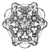
The sun gear meshes with 3 (4) inner planetary gears. The inner planetary gears also mesh with 3 (4) outer planetary gears. The outer planetary gears also mesh with the ring gear.
number of teeth of the ring gear: 2*N
number of teeth of the sun gear: 1*N
=> stationary gear ratio i12=+2 => torque distribution 50:50


