Slide
One of the first things that I learned early in my engineering career was that there is almost never a basic error in basic engineering principles. The next thing I learned is that the principles need to be applied correctly or you can end up with some really strange results.
I have had a life with two major avocations, one being heavily industrial and the other deeply wrapped up in the motor racing business with major emphasis in open wheel racing and smaller sports cars.
It just so happens that both of these avocations were happily guided by the objective to simplify and add lightness. Or at least the racing side was like that; the industrial side was simplify and meet budgets and schedules.
I had more than a bit of success in both. Industrially I found myself, with two different companies, responsible for 600 man (and the smattering of women here and there) engineering groups. That was before I woke up and realised that the real challenges and money was in managing the money and overall people side of the businesses. Racing wise, I enjoyed about fifty years of driving and several years in the supporting design and building what turned out to be about 150 open wheel and sports racing cars. All this as just background.
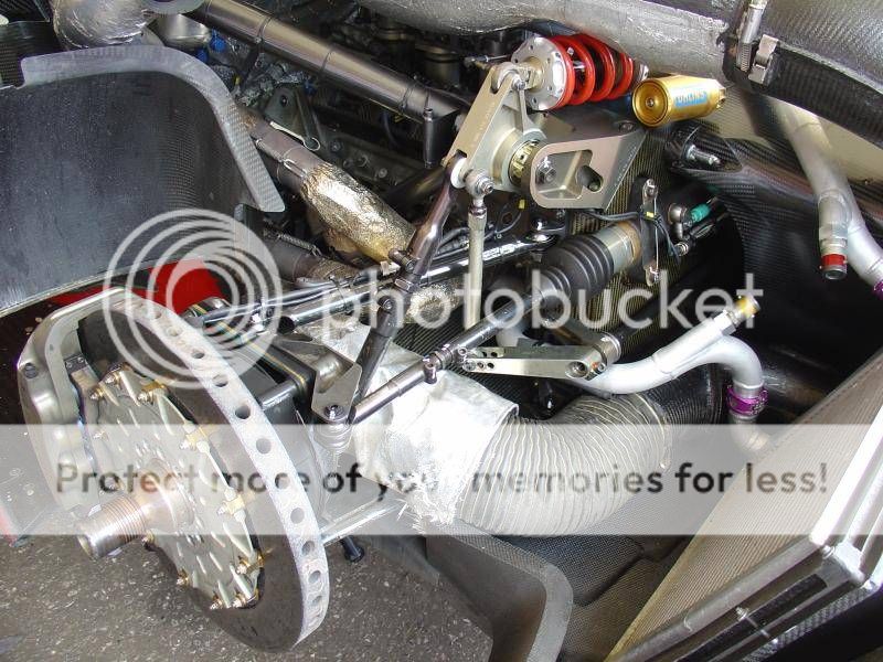
In the race car design and building days suspension bits were typically fabricated as follows: Using 1 inch 16 SWG mild steel tubing cut to semi-finished length, set up in a lathe and bore each end for a light press fit of a threaded bushing. Take steel rod set up in a lathe and trim outside diameter for the press fit above then
Bore to suit threading followed by parting off bushing of say 30mm long. Cut right hand threads in half, left hand in the other half. Assemble bushings in the suspension bits and make a deep penetration end weld to join. Put back into lathe to face off each end and to make final finished length. Voila; you had a finished suspension bit that was assuredly concentric and true to length. For something like this we would typically use 10 or 12 mm rod end/unibal/heim joint depending what you call them in your part of the world. Assembled with a suitable jam nut you had something that was wobble free, concentric and infinitely adjustable.
You raised the subject of Warren Young’s text, Roark’s Formulas … etc. You are correct; I never read Young, he first published in 1989 which is too new for me. However I am familiar with Roark’s works as some of the guys that used to work for me pulled Roark out a few times for my reference. Never had to study Roark, (he was Univ of Wisconsin), but I can assure you that at Purdue we learned from the directly equivalent.
Interestingly again, when my father died I grabbed his remaining Purdue text books, (he having graduated near top of class in 1927). One of the books was a structural handbook published in 1923. That one varied only in layout with my texts and those that I have been exposed to since. The basics were all in place even then.
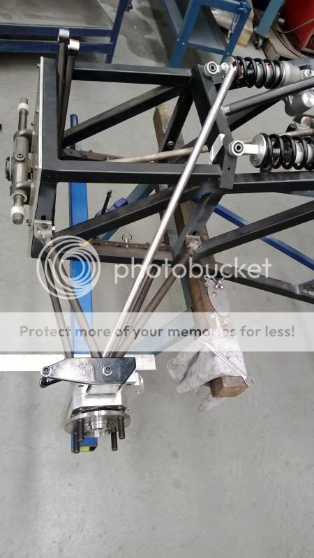
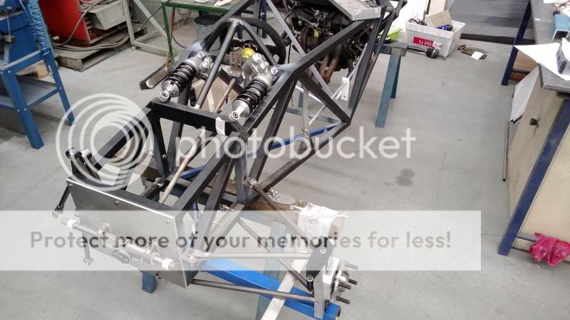
And yes, the pushrod in question in this thread is subject to combined compression and bending. The bending due to the fact that the rod ends are subject to the of the pivots they are attached to. If it weren’t for the arc influences the push rod would be subject only to tension and compressive forces.
If we look at the 10mm rod end example that I described earlier we have a push rod that is designed for a dynamic loading of probably 10 kN (2250 pound force). The rod end probably has a coefficient of friction of 0.1when broken in and if of good quality, slightly higher coefficient if of poorer quality. This means that the rotating force within the rod end when subject to max dynamic force is 1 kN (225 pound force). Now this force acts at a radius of about 10mm depending on the design of the rod end. Thus we are imparting a max bending moment on the push rod of 10 Newton meters (less than 8 foot pounds).
I am glad to see that by post 37 you admit this, “Mostly though it just boils down to an academic argument”. I think we both can heartedly agree that the bending moment for such an application can be easily ignored.
Oh, and Greg, at Purdue we also were analysing warren truss intermediate loads with a 12 inch log-log duplex slide rule. Just for old times sake I just pulled out my old K&E with 20 scales and gave it slide back and forth just to remind me. And yes we would take into full effect the end joint properties that properly applied. We also ignored those which fell outside of the calculation properties of a slide rule. My father probably had to do the same.
As proof of the pudding, even to this day I don’t think we have ever had a suspension failure or tube frame failure on any of the 250 race cars we built, (accidents excepted). 


