for the past day I've been running through suspension iterations on paper trying to make sense of all of the angular variations that occur in a 'traditional' pushrod suspension. I know I will be overlooking some things, but looking at the layout of the current project (a motorbike powered formula-like car) I've encountered what seems to be a significant problem:
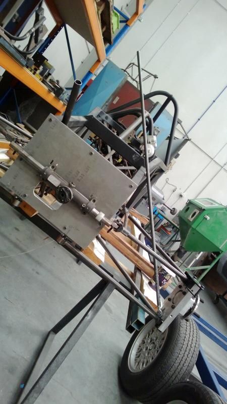
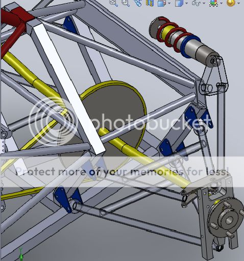
The front suspension looks like this with the working angle of wishbone/damper and pushrod quickly mocked up. Essentially they are all in the same plane with the bellcrank axis perpendicular to the working angle:
The pushrod is angled back to the cockpit around 10 degrees.
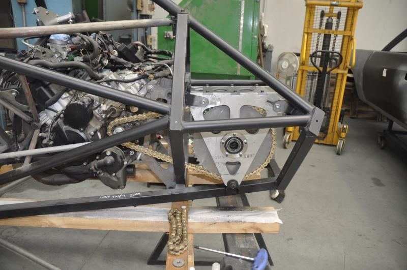
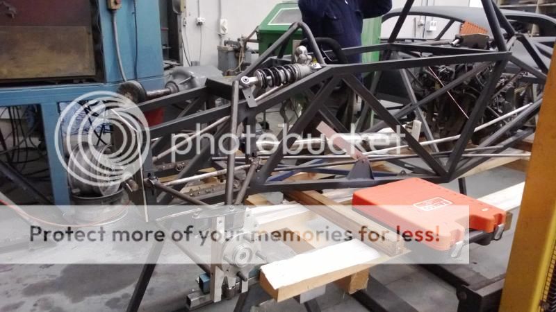
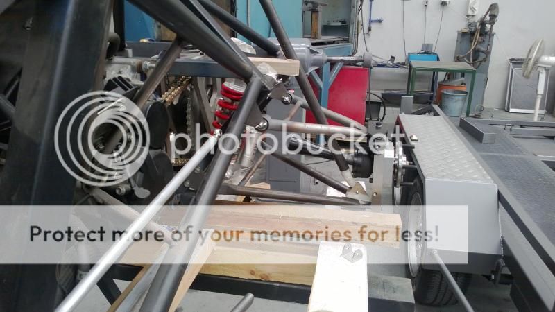
The problem is more at the rear. The structure looks like this in side view because the plan was to run the dampers across the very rear of the car.
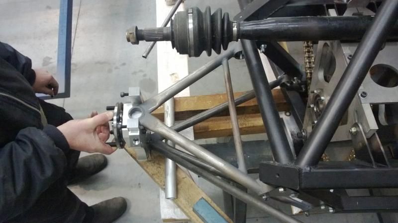
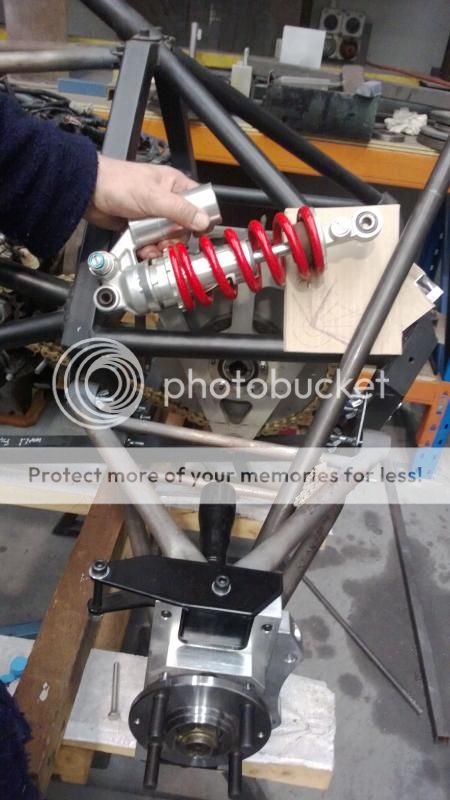
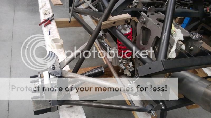
We would now prefer to run the damper longitudinally to the point in the middle of the pic where two tubes meet. Either way the problem with the desin is one of packaging, which can be partly seen in this picture:
In plan view the A-arm gets in the way of the pushrod - running . We can get around that by increasing the angle of the pushrod or by using a 'K' arm - basically a bent link in the aft section of the A arm with another tube going forwards. I don't like the idea too much, but am open to other solutions. The bigger issue is the deviation in plan view - should I run the pushrod further back to clear a straight link it would be really quite an accute angle and I assume this will add another variable that I have to account for?


