If you admire craftsmanship and ingenuity---and we know we do---you will get a kick out of this 7-cylinder radial engine built up from air-cooled VW parts. Check out the lathe and mill work.


Member
Posted 04 October 2014 - 11:00
If you admire craftsmanship and ingenuity---and we know we do---you will get a kick out of this 7-cylinder radial engine built up from air-cooled VW parts. Check out the lathe and mill work.
Advertisement

Member
Posted 04 October 2014 - 11:22
Amazing. I wouldn't be running it too fast or long before organising some lube to the valve gear! Actually I didn't see any lube system detail?

Member
Posted 04 October 2014 - 11:34
Member
Posted 04 October 2014 - 19:54
Amazing. I wouldn't be running it too fast or long before organising some lube to the valve gear! Actually I didn't see any lube system detail?
From the exhaust smoke it appears to be premix. Castrol, one hopes.

Member
Posted 05 October 2014 - 00:15
Very nice.
Here is another unusual (and much fiercer-sounding) radial.
http://www.desertair...0cc-radial.html
Edited by Wuzak, 05 October 2014 - 00:17.
Member
Posted 05 October 2014 - 03:46
From the exhaust smoke it appears to be premix. Castrol, one hopes.
No doubt the valve gear is "pre-squirt".

Member
Posted 05 October 2014 - 03:48
Edited by manolis, 06 October 2014 - 04:10.
Member
Posted 05 October 2014 - 03:52
Very nice.
Here is another unusual (and much fiercer-sounding) radial.
Fabulous sound.
Member
Posted 05 October 2014 - 15:49
Very nice.
Here is another unusual (and much fiercer-sounding) radial.
$5000 for a model airplane engine. I'm sure it's worth every penny, but $5000 for a model airplane engine.
Member
Posted 05 October 2014 - 15:54
No doubt the valve gear is "pre-squirt".
The story goes that someone asked W.O. Bentley how his rotary aero engine was lubricated. He looked at the man with a puzzled expression and said, "Try and stop it."

Member
Posted 05 October 2014 - 22:25
$5000 for a model airplane engine. I'm sure it's worth every penny, but $5000 for a model airplane engine.
It is a BIG model aeroplane. So I guess big bucks for the components.
As for the VW7, VW used from memory the pushrods to feed oil to the top which then hopefully gets back down the pushrod tubes. So one would have thought that would work here too. There has to be a pressurised oil system somewhere to lube the crank and ancillaries.
I bet thye mixtures are all over the place too, a common plenum fed at all angles. Though equal lengths at least.
Edited by Lee Nicolle, 05 October 2014 - 22:31.
Member
Posted 05 October 2014 - 23:04
That was the original purpose of the centrifugal compressor in aero engines - to try to get even mixture distribution.
Looks like that engine would be similar to early radial engines if the oil supply to the valve gear is as you suggest Lee. That is, a total loss oil system.
Member
Posted 06 October 2014 - 09:10
That was the original purpose of the centrifugal compressor in aero engines - to try to get even mixture distribution.
Looks like that engine would be similar to early radial engines if the oil supply to the valve gear is as you suggest Lee. That is, a total loss oil system.
VWs are fairly basic,,, but do have oil to the valve train and valve covers.
While an interesting concept it should be practical. With some work I guess it could be. The very major work done to make a crankshaft and I guess control blades etc yet alone the making a 7cyl camshaft and distributor is over shadowed by the lack of valve covers and top end oiling

Member
Posted 06 October 2014 - 12:59
yep, I saw the VW radial a while back. Impressive.

Member
Posted 06 October 2014 - 18:23
Interesting enough, but they did kinda take the easy way out with poppet valves and all......I mean, make it a double row with sleeve valves a'la Bristol and *maybe* we can talk....
Just kidding. This thing is awesome. I wasn't suprised a bit to see that it came out of Holland. Those crazy Dutch are always tilting at windmills (pun fully intended).
Member
Posted 07 October 2014 - 07:52
VWs are fairly basic,,, but do have oil to the valve train and valve covers.
While an interesting concept it should be practical. With some work I guess it could be. The very major work done to make a crankshaft and I guess control blades etc yet alone the making a 7cyl camshaft and distributor is over shadowed by the lack of valve covers and top end oiling
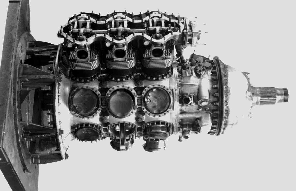
Here is the "camshaft" for the R-2800.

There is one cam ring for the front row and one for the back row. They had 4 lobes, and operated at an 8:1 reduction.
Since he is using a one piece master rod, he must be using a two piece crank. I wonder how he has joined the two together.
Edited by Wuzak, 07 October 2014 - 08:06.
Member
Posted 07 October 2014 - 11:23
Edited by Kelpiecross, 07 October 2014 - 11:24.
Member
Posted 07 October 2014 - 12:07
If you had one lobe that would mean it would activate the valves of every cylinder in sequence.
The firing order of a 9 cylinder radial being 1-3-5-7-9-2-4-6-8.
I am thinking that multiple lobes would help prevent the valves opening every revolution.

Member
Posted 07 October 2014 - 12:21
If you had one lobe that would mean it would activate the valves of every cylinder in sequence.
The firing order of a 9 cylinder radial being 1-3-5-7-9-2-4-6-8.
I am thinking that multiple lobes would help prevent the valves opening every revolution.
Quite right.
You need a number of lobes and a reduction ratio such that the next lobe opens the valve of the next cylinder but one in never-ending sequence.
Advertisement
Member
Posted 07 October 2014 - 14:23
Yes, as Manolis et. al. have pointed out, radials have a number of interesting characteristics. The more you look, the more interesting they get.
Member
Posted 07 October 2014 - 14:28
Hello.
Quote from http://www.pattakon....ttakonPatAT.htm
In comparison to the convetional Radial engine:
(master rod / articulated slave rods, click http://www.pattakon....atAT/Radial.exe to download
the controllable windows exe program / animation)
the Cross-Radial with the four cylinders and with the forked connecting rods is a true "vibration free" engine (better balanced than the "master-slave-rods" Radial regardless of the number of cylinders of the later), it is also a true "symmetrical" engine: all the four cylinders run under the same conditions: same piston stroke, same piston motion profile, same connecting rod leaning (thrust loads), etc.
As the Radial.exe at http://www.pattakon....atAT/Radial.exe demonstrates, a typical Radial (master rod / slave rods) cannot help running with substantially different piston strokes in different cylinders.
Did you ever think of such asymmetry?
When you run the abovementioned “windows-exe” visual-basic program spot on the significant difference among the master cylinder piston stroke and the piston strokes of the “side” cylinders; if you press the c key on the keyboard, the program shows the direction and strength of the inertia force resulting from the motion of the center of gravity of the set of all pistons: there is a noticeable (and variable) phase difference between the direction of the overall inertia force and the center of the crankpin as well as a variable amplitude of this inertia force, i.e. a radial - no matter how many cylinders it comprises - cannot be fully balanced without using additional “external” balancing shafts.
With the slide-bars at left –top you can chose the number of cylinders (from 1 to 35), the “con-rod to stroke ratio” (master-rod) and the eccentricity of the crank-side-pins of the slave rods.
Despite their asymmetry (think of trying to optimize an engine wherein some cylinders run at more than 5% longer piston stroke that others, and wherein different pistons follow substantially different motion profiles), the Radial engines dominated in the aviation because of their lightweightness and “packaging”.
By the way, take a look at the matter added recently to the Portable Flyer at http://www.pattakon....pattakonFly.htm
Thanks
Manolis Pattakos
Thanks! A person could spend some hours fooling around with this.
Member
Posted 07 October 2014 - 16:43
Yes, as Manolis et. al. have pointed out, radials have a number of interesting characteristics. The more you look, the more interesting they get.
Yes, but he picked on the different strokes that result from the master/slave con-rod system. If that really bothers you, try the Systeme Canton-Unné as used in the Salmson radials!

Edited by Allan Lupton, 07 October 2014 - 16:47.
Member
Posted 08 October 2014 - 00:14
If you had one lobe that would mean it would activate the valves of every cylinder in sequence.
The firing order of a 9 cylinder radial being 1-3-5-7-9-2-4-6-8.
I am thinking that multiple lobes would help prevent the valves opening every revolution.
Quite right.
You need a number of lobes and a reduction ratio such that the next lobe opens the valve of the next cylinder but one in never-ending sequence.
The last piece of the puzzle is - the cam rotates in the opposite direction to the crank. We need Manolis to provide an animation!
Member
Posted 08 October 2014 - 01:00
The last piece of the puzzle is - the cam rotates in the opposite direction to the crank.
Thanks. I was trying to work out how the cam would work with lobes 90° and cylinders 40° apart, meaning that the next cylinder to activate is 80° away.
Member
Posted 08 October 2014 - 03:19
The last piece of the puzzle is - the cam rotates in the opposite direction to the crank. We need Manolis to provide an animation!
Member
Posted 08 October 2014 - 04:08
A 9 cylinder radial based on Honda XR600 cylinder barrels and heads, with overhead cams.
http://thekneeslider...-radial-engine/
http://thekneeslider...running-strong/
Member
Posted 08 October 2014 - 05:38

Edited by manolis, 08 October 2014 - 05:55.
Member
Posted 08 October 2014 - 06:33
The last piece of the puzzle is - the cam rotates in the opposite direction to the crank. We need Manolis to provide an animation!
Perhaps not the last piece.
The number of inlet (or exhaust) cam lobes must be equal to (number of cylinders - 1) / 2 so 4 for a 9 cylinder, 3 for a seven cylinder, 2 for a 5 cylinder and 1 for a 3 cylinder.
Camshaft speed of course needs to be engine speed / (2 x number of lobes).
Member
Posted 08 October 2014 - 08:19
Perhaps not the last piece.
The number of inlet (or exhaust) cam lobes must be equal to (number of cylinders - 1) / 2 so 4 for a 9 cylinder, 3 for a seven cylinder, 2 for a 5 cylinder and 1 for a 3 cylinder.
Camshaft speed of course needs to be engine speed / (2 x number of lobes).
Yes that's right - I thought that was a bit too technical for this threadn so did not detail it.
Also too technical are the reasons why, splendidly colourful as the animation is, one row of the four-cylinder two-stroke is not as balanced as is claimed and wouldn't work with just a turbo-supercharger. Mind you as there is no induction system shown . . .

Member
Posted 08 October 2014 - 08:36
Great thread, big piston radials are fascinating things.
My favourite radials are those WW! ones where the crank is fixed to the firewall and the whole cylinder assembly rotates i.e a rotary in those days. It helped cooling but made fuel distribution tricky. So the power control was largely by the ignition. As they fly a huge wasp type noise climbing, then as they dive total silence as the pilot cuts the mags. At the bottom of the dive he flicks the mag. switches on and HOPEFULLY the prop rotation fires it up.
You watch the demo. flight heart in mouth as the plane rushes towards the ground noiselessly praying it restarts.
Member
Posted 08 October 2014 - 10:02
A 9 cylinder radial based on Honda XR600 cylinder barrels and heads, with overhead cams.
http://thekneeslider...-radial-engine/
http://thekneeslider...running-strong/
This one I like. It seems far more practical and complete.
Though I dont know as I would like to fly in a plane powered by it! Swamp boat maybe
LPG is different.
I think his brake cooling is a little much,, a decent washer pump misting water through the brake vanes should be enough.
And run under the Hills Hoist.
Member
Posted 08 October 2014 - 11:17
If you keep your eyes open at garage sales, swap meets, Fleabay, and so on, you can find these old operator manuals on radial engines (and all kinds of combat equipment). Evidently, they printed plenty for the war effort.
These manuals are really quite excellent -- extremely straightforward and to the point, since they were meant to educate people with limited knowledge in a very short time. No frosting on it. Terse, in a word. Lots of illustrations and data charts and other info for rapid reference.

Member
Posted 08 October 2014 - 11:45
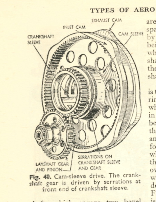
How different, how very different, from the Bristol sleeve valve drive gear:

Member
Posted 08 October 2014 - 12:32
The Armstrong Siddeley Deerhound was a 3 row air-cooled radial. It had a differnt valve system - overhead cam..

Member
Posted 08 October 2014 - 13:37
Member
Posted 08 October 2014 - 19:24
Great thread, big piston radials are fascinating things.
My favourite radials are those WW! ones where the crank is fixed to the firewall and the whole cylinder assembly rotates i.e a rotary in those days. It helped cooling but made fuel distribution tricky. So the power control was largely by the ignition. As they fly a huge wasp type noise climbing, then as they dive total silence as the pilot cuts the mags. At the bottom of the dive he flicks the mag. switches on and HOPEFULLY the prop rotation fires it up.
You watch the demo. flight heart in mouth as the plane rushes towards the ground noiselessly praying it restarts.
I love the radial rotaries as well. They are about the most enchanting piston engines ever devised.
And while this might be a little hard to wrap one's brain around, the rotary was successful because it answered or avoided many of the issues that plagued IC piston engines of the era. It worked as well or better than anything else going at the time, which is worth a moment of contemplation.
Member
Posted 09 October 2014 - 03:17
The PatAT Cross-Radial is not using the crankcase as the scavenging pump (see at http://www.pattakon....ttakonPatAT.htm the respective single cylinder animation). A single turbocharger for all the four cylinders is adequate (just like in the giant marine low-speed two stroke engines: a single turbocharger can feed all cylinders).
Please explain where you see the problem.
Thanks
Manolis Pattakos
Scavenging requires a positive pressure differential (inlet pressure > exhaust pressure) which will not exist under starting, transient and certain other conditions. One solution would be a motor/generator unit which would have the additional benefit of allowing efficiency gains via compounding. (Thought I should bring this thread back towards F1  )
)
Member
Posted 09 October 2014 - 05:16
Member
Posted 09 October 2014 - 09:56
How different, how very different, from the Bristol sleeve valve drive gear:
HELP !
Advertisement
Member
Posted 09 October 2014 - 11:41
Perhaps not the last piece.
The number of inlet (or exhaust) cam lobes must be equal to (number of cylinders - 1) / 2 so 4 for a 9 cylinder, 3 for a seven cylinder, 2 for a 5 cylinder and 1 for a 3 cylinder.
Camshaft speed of course needs to be engine speed / (2 x number of lobes).
Member
Posted 09 October 2014 - 11:50
I love the radial rotaries as well. They are about the most enchanting piston engines ever devised.
And while this might be a little hard to wrap one's brain around, the rotary was successful because it answered or avoided many of the issues that plagued IC piston engines of the era. It worked as well or better than anything else going at the time, which is worth a moment of contemplation.
Member
Posted 09 October 2014 - 12:19
Thanks, Gruntguru, for explaining the turbocharger problem which I'd have done, had I not been elsewhere.
There is a language problem in the refutation of GG's point as a turbo-supercharger (colloquially turbocharger) is a device that uses a turbine to drive a compressor (and at start-up there is no exhaust for the turbine to extract energy from). What seems to be being described by Manolis is an electrically-driven supercharger, which can of course run before the engine rotates.
As for the balance of the four-cylinder unit on its own, I'd say that the normal effects of trying to balance reciprocating mass using rotating mass are not cancelled out, as they are with various conventional configurations of multi-cylinder engine.
Member
Posted 09 October 2014 - 22:23
Member
Posted 09 October 2014 - 22:25
Member
Posted 09 October 2014 - 23:02
Sorry Manolis, but the "Pattagon" link gets to a site with no indication of its credentials and all that can be seen is a lot of unhelpful text - I expect it has animated displays if one knows how to trigger them.
I am too old to be impressed by that sort of thing, but also too old to have total recal of all the Theory of Machines lectures I heard in enough detail to reproduce them here.
Again we seem to have a language difficulty as I cannot see that a "scavenge pump" is relevant to "all the four cylinders" of your engine - it's the crankcase that has to be scavenged of oil which is part and parcel of the dry sump lubrication system you would have to have.
Member
Posted 09 October 2014 - 23:36
He means an air pump for 2 stroke cylinder scavenging.

Member
Posted 10 October 2014 - 02:28
How different, how very different, from the Bristol sleeve valve drive gear:
I think one of those is out by one tooth ....
Member
Posted 10 October 2014 - 03:32
Well spotted G.M.
Member
Posted 10 October 2014 - 03:39
Edited by Kelpiecross, 10 October 2014 - 04:05.
Member
Posted 10 October 2014 - 03:51


© MOTORSPORT NETWORK 2024. All rights reserved. Community Forum Software by IP.Board
