Jump to content


Photo
- - - - -

7-cylinder radial engine built from air-cooled VW parts


  • Please log in to reply
84 replies to this topic

#51 manolis

manolis
  • Member

  • 935 posts
  • Joined: May 03

Posted 10 October 2014 - 06:32

Hello Kelpiecross.

Here is a GIF animation of the Radial with 11 cylinders.

Radial_Cam_Anim.gif

Think of the green (or of the purple) circles at the apexes of the polygons as the points wherein the “overlap” happens.

All the idea of this crank / cam / valve mechanism for 4-stroke Radials is to ignite the k cylinder (wherein the compression completes), then to omit the k+1 cylinder (wherein the overlap occurs), then to ignite the k+2 cylinder (wherein the compression completes), then to omit the k+3 cylinder (wherein the overlap occurs) and so on.
Think of the mechanism like a double “rotary” / “radial” vernier scale.


The eleven black line intervals (radially arranged along the cylinder axes) have the same length (the piston stroke of the piston connected to the crankshaft via the master rod.

The “piston pins” (blue circles) have a radius equal to 1/10 of the “master piston” stroke. This way you can compare the strokes of the various pistons.

As you can see, the side cylinders have some 10% longer piston stroke.

As you can see, the maximum angle between the connecting rod of the lower cylinder and its cylinder axis is substantially bigger (say 50%) than the maximum angle between the master connecting rod and its cylinder axis (heavy thrust loads).

As you can see, the left side cylinder and the right side cylinders have substantially different piston motion profiles: the one set compresses quickly and expands slowly, the other set expands quickly and compresses slowly.

Despite all these, the Radial engines dominated in the airplanes for many years.

Thanks
Manolis Pattakos

Advertisement

#52 Allan Lupton

Allan Lupton
  • Member

  • 4,052 posts
  • Joined: March 06

Posted 10 October 2014 - 07:17

I shall give up after this.

I have now had detailed explanations of missed points, probably, as I wrote before, because of language difficulty.


e.g. 1

I wrote that "the "Pattagon" link gets to a site with no indication of its credentials"

Manolis wrote that "the pattakon.com web site has been scanned and is malware-free"

If that's all you need to consider before you believe any old thing posted on the internet, you will have great difficulty.


e.g.2

I wrote: "Again we seem to have a language difficulty as I cannot see that a "scavenge pump" is relevant to "all the four cylinders" of your engine - it's the crankcase that has to be scavenged of oil which is part and parcel of the dry sump lubrication system you would have to have.”

Manolis shows us a cross-section of a wet-sump marine engine which therefore has no scavenge pump and refers to "Several cylinders use the same turbocharger for the scavenging"


#53 Kelpiecross

Kelpiecross
  • Member

  • 1,730 posts
  • Joined: October 10

Posted 10 October 2014 - 12:10


Thank you Manolis.

#54 desmo

desmo
  • Tech Forum Host

  • 29,522 posts
  • Joined: January 00

Posted 10 October 2014 - 20:24

Scavenging can mean two quite different things to people accustomed to two or four stroke engines. Crankcase scavenging is the normal way for the air/fuel/oil mixture to be introduced into the cylinder in small two stroke engines rather than it relating to oil pumps- https://en.wikipedia...o-stroke_engine That page has a small animation that shows the process adequately well.

#55 Lee Nicolle

Lee Nicolle
  • Member

  • 11,061 posts
  • Joined: July 08

Posted 11 October 2014 - 00:35

From what I see the 9cyl Honda base engine would just use standard cylinder heads and cams. The trick then is getting the crank phasing to be 100% accurate. And working out all the cam drive arrangements. Which would have to be far easier than using a 7cyl cam and pushrods.


As a race car engine builder oil control will always be a problem. You have NINE [or seven] seperate engines to scavenge effectivly, most of which are not running at original angles. Scavenging cam covers may be ok, just. Pressure feeding cranks in engines upside down too will be a bit average. Plus all that oil then has to be kept away from the piston and ring area.


For mine I will stick to simple engines where the pan is on the bottom and you scavenge from where gravity puts the oil.

Those radial aircraft engines must have been very suss, all of what I have mentioned plus all the gears and drives.

Does any aircraft use radials now?  The only aircraft I remotely have had anything to do with a 4 cyl Lycomings. A fairly normal style of engine. Though evidently  [for the above reasons] are not permitted for remotely any aerobatic manouvres. From what I am told you can throw them about a fair bit, bank at 45 deg and climb and descend at about the same. Eg crop dusters


#56 Wuzak

Wuzak
  • Member

  • 8,501 posts
  • Joined: September 00

Posted 11 October 2014 - 01:11

Since we don't see the cam arrangement for the VW based engine, it is quite possibel that the valves are operated by 7 cams in the crankcase, instead of the cam rings.


The Honda based engine obviously uses the standard chain drive, driven by shafts and gears from the crankshaft.


xr600radial2.jpg


Incidentally, chain drive in aero engines was not usual practice.


As for radials in use today, there are  few older types still running around, Ther eare also some newer types:


http://en.wikipedia....ki/Sukhoi_Su-31

http://en.wikipedia....T-411_Wolverine


Rotec makes a couple of radials which are used in kit and replica aircraft


http://www.rotecradi...R3600/R3600.htm

http://www.rotecradi...R2800/R2800.htm


#57 manolis

manolis
  • Member

  • 935 posts
  • Joined: May 03

Posted 11 October 2014 - 02:52

Hello Desmo and Lee Nicolle.

Talking for the scavenging of the 4-cylinder Cross-Radial two-stroke PatAT engine:

the “oil scavenging” (related, among others, with the pressurized lubrication of the crankshaft bearings, with the splashed "over-lubrication" of the cylinder liners, with the application of oil scraper rings, with the collection / cleaning / cooling and recycling of the surplus oil) is as in the conventional 4-stroke Radial engines,

while the “gas scavenging” (related with the sweeping of the burnt gas out of the cylinders and the filling of the cylinders with fresh air / mixture) is not related with the crankcase (which needs not be “pressurized”); an external scavenging pump (for instance a turbocharger) feeds all the cylinders with pressurized air or mixture.


Talking for the balancing of the 4-cylinder Cross-Radial PatAT engine:

the fact that the center of gravity of the set of the four pistons (all moving onto the same plane) is moving at constant eccentricity from the crankshaft axis and is rotating in phase with the crank-pin center (as explained in a previous post), enables (by using a pair of balance webs secured to the crankshaft) the complete elimination of the unbalanced inertia force and of the unbalanced inertia moment (a V-8 has a small unbalanced inertia force of 4th order and a very small unbalanced inertia moment of 4th order too). The inertia torque is half of that of the best V-8 four-stroke in case the two engines use same pistons, same connecting rods, same stroke. Both engines are even-firing with equal intervals between combustions.


With:
top vibration-free quality (much better than the conventional Radials and better than the best V-8),
true symmetrical structure (all the four cylinders run under the same conditions: same piston stroke, same piston motion profile, same connecting rod leaning),
higher power to weight ratio (as a two-stroke it has one combustion per cylinder per crankshaft rotation, as a two-stroke it is rid of valve train),
simple and power-efficient scavenging (a turbocharger uses the energy of the exhaust gas),
and four-stroke-like lubrication,
the PatAT Cross-Radial seems a good alternative for aviation applications.

Thanks
Manolis Pattakos

Edited by manolis, 11 October 2014 - 02:57.


#58 Kelpiecross

Kelpiecross
  • Member

  • 1,730 posts
  • Joined: October 10

Posted 11 October 2014 - 03:40

Since we don't see the cam arrangement for the VW based engine, it is quite possibel that the valves are operated by 7 cams in the crankcase, instead of the cam rings.
 
The Honda based engine obviously uses the standard chain drive, driven by shafts and gears from the crankshaft.
 
xr600radial2.jpg
 
Incidentally, chain drive in aero engines was not usual practice.
 
As for radials in use today, there are  few older types still running around, Ther eare also some newer types:
 
http://en.wikipedia....ki/Sukhoi_Su-31
http://en.wikipedia....T-411_Wolverine
 
Rotec makes a couple of radials which are used in kit and replica aircraft
 
http://www.rotecradi...R3600/R3600.htm
http://www.rotecradi...R2800/R2800.htm


If turboprop engines didn't exist I would think that planes would still use big air-cooled radials and not liquid cooled inline engines.
The Caribou (with radial engines) was used up until a few years ago by the RAAF.

#59 Wuzak

Wuzak
  • Member

  • 8,501 posts
  • Joined: September 00

Posted 11 October 2014 - 04:23

If turboprop engines didn't exist I would think that planes would still use big air-cooled radials and not liquid cooled inline engines.
The Caribou (with radial engines) was used up until a few years ago by the RAAF.


Big LC piston engines basically disappeared after the introduction of the turbojet.


Big radials captured the transport market, as they had before the war.


Advertisement

#60 PJGD

PJGD
  • Member

  • 143 posts
  • Joined: April 04

Posted 11 October 2014 - 12:22

You could have a new radial engine if you want one: http://clearenergysy...technology.html


PJGD


#61 manolis

manolis
  • Member

  • 935 posts
  • Joined: May 03

Posted 12 October 2014 - 07:58

Hello PJGD.

I don't know about the credentials of the clearenergysystems.com web site you write, but, seeing a fake photo at the top of their "home page", what I think is that something is wrong with them.

The backside of the truck (at left) is real, the rest "photo" is CAD.
How to check it?
Just open the "photo" with microsoft paintbrush and "fill" with some color any flat surface.
In a real photos there are not such surfaces.

Their Radial engine is a conventional 9-cylinder aircooled 30lt with pushrods for the motion of the valves.
The angle between the intake / exhaust valves seems as more than 80 degrees (bad shape of combustion chamber).
They use natural gas as fuel.
To compare the CO2 emitted per kWh by their Radial with that of a Diesel of similar power is not fair (the one fuel has much more carbon and less hydrogen).

Reasonably they will use multi point injection.
I wonder if they use different injection and ignition maps for different cylinders (read about the "internal" asymmetry of the master-slave rods Radial as explained in previous posts).


If somebody needs a new Radial, there is also the option to contact the guy who made, with VW parts, the 7-cylinder Radial proposed by Magoo at the top of this thread.

Thanks
Manolis Pattakos

Edited by manolis, 12 October 2014 - 08:21.


#62 PJGD

PJGD
  • Member

  • 143 posts
  • Joined: April 04

Posted 12 October 2014 - 14:36

Manolis, Clear Energy Systems have several patents that cover the details of their radial engine.  Here is one: US 8567354 B2


PJGD


#63 manolis

manolis
  • Member

  • 935 posts
  • Joined: May 03

Posted 13 October 2014 - 02:50

Hello PJGD.

I took a look at their US patent at
http://patft.uspto.g...4&RS=PN/8567354
and at their US patent application.

I am the last to judge their Intellectual Property.


But what do you think / feel seeing "photos" like:

gen_onet.png

at the their "central" G1000 page at http://clearenergysy...com/g1000.html?


If you talk with them, advice them to take a real container, put their logos on it, tow the container at the back of a pickup truck that can be driven by a non-commercial driver and get the necessary photos.

Thanks
Manolis Pattakos

#64 manolis

manolis
  • Member

  • 935 posts
  • Joined: May 03

Posted 14 October 2014 - 13:40

Hello Kelpiecross.

In your post #41 you write:
“The rotary engine is also interesting in that, despite its resemblance to a radial engine it was a true "rotary" - the pistons described a circle and they didn't accelerate up and down as in a "normal" engine. Apparently the rotaries were notably smoother in their running than a similar-sized radial.”


In the Rotary (radial) the pistons move around a circle; but their motion is a rotation with variable angular velocity.

If you take the center of gravity of the set of all the pistons, it is not standstill.

The unbalanced inertia forces (and smoothness) are similar with those of a conventional Radial.

An advantage of the Rotary is that it needs not balance webs (this saves weight).

A disadvantage of the Rotary is its big moment of inertia: the spinning casing is a big flywheel; in order to change its direction, you need a lot of torque and a lot of time.
During quick maneuvers, the necessarily delicate airplane frame is heavily loaded by the gyroscopic rigidity of the engine; see in the youtube video at https://m.youtube.co...h?v=bzbVwiIeM0M (or read at http://www.pattakon....pattakonFly.htm ) how much stable is the set of the two parallel flywheels when they spin at the same direction.

Thanks
Manolis Pattakos

Edited by manolis, 14 October 2014 - 13:45.


#65 Kelpiecross

Kelpiecross
  • Member

  • 1,730 posts
  • Joined: October 10

Posted 15 October 2014 - 03:35


Almost a true rotary then.

If you like gyroscopes - this is interesting:


#66 manolis

manolis
  • Member

  • 935 posts
  • Joined: May 03

Posted 15 October 2014 - 05:01

Hello Kelpiecross.

With the flywheel rotatably mounted (and spinning quickly) at the one end of the shaft, as in the youtube video of your post, the hand of the professor has to apply at the other end of the shaft an upwards force equal to the weight of the shaft and of the flywheel.

This force times the length of the shaft is the torque that changes progressively the orientation of the flywheel axis (or shaft axis).

Imagine a lightweight airplane frame (the above “shaft”) having at its nose a spinning Rotary engine of big gyroscopic rigidity (the above “flywheel”).
Instead of the hand of the professor, now the wings of the airplane apply the required upwards force to the airplane frame (it is the lift applied by the air onto the wings of the airplane) that keeps the Rotary engine from falling.
This force (lift) is offset relative to the Rotary engine; in order to avoid the continues turning of the airplane about its vertical axis (corresponding to the turning of the shaft in the video) the airplane needs an opposite torque.
In order to go straight forward, the airplane with the Rotary at its nose has to keep its rudder (yaw control) substantially turned!

This problem exists with the Radials and the rest engines, too, but their smaller gyroscopic rigidity softens it.

Compare the case to the OPRE propulsion unit at he bottom of the http://www.pattakon....pattakonFly.htm web page, wherein the total gyroscopic rigidity is zero.

Thanks
Manolis Pattakos

#67 gruntguru

gruntguru
  • Member

  • 7,642 posts
  • Joined: January 09

Posted 15 October 2014 - 05:06

Amazing!


#68 GreenMachine

GreenMachine
  • Member

  • 2,646 posts
  • Joined: March 04

Posted 15 October 2014 - 06:52

This was actually used tactically, to turn the aircraft more tightly than was possible merely by the control surfaces.


Edited by GreenMachine, 15 October 2014 - 06:52.


#69 gruntguru

gruntguru
  • Member

  • 7,642 posts
  • Joined: January 09

Posted 15 October 2014 - 08:20

In one direction only. Turning the other way was slower.


#70 GreenMachine

GreenMachine
  • Member

  • 2,646 posts
  • Joined: March 04

Posted 15 October 2014 - 11:02

Yes.  I was going to add that I wondered if that predictability was a problem in a dogfight, but I have seen no reference to this being the case.


#71 gruntguru

gruntguru
  • Member

  • 7,642 posts
  • Joined: January 09

Posted 15 October 2014 - 23:13

I guess it depends who is pursuing who in the dogfight. If your aircraft has a weakness and you are the pursuer, it is easier for your opponent to exploit it eg the Merlin's inability to sustain negative G.


#72 bigleagueslider

bigleagueslider
  • Member

  • 1,235 posts
  • Joined: March 11

Posted 22 October 2014 - 05:14

Interesting proposition.


Turbofan engines have definitely captured all of the market for aircraft operating at high speeds or high altitudes. Turboshaft engines have almost all of the market for rotorcraft and smaller fixed wing aircraft. But recip engines still have most of the market for small fixed wing GA aircraft.


With large commercial ships, big low-speed 2T CI recip engines are preferred. With commercial locomotive applications, large 4T recip CI diesels are preferred. Commercial heavy trucks almost all use 4T, CI turbo-diesel engines. Automobiles use a mix of 4T recip diesel engines and NA/turbo SI gasoline engnes. But none of these are air cooled.


#73 gruntguru

gruntguru
  • Member

  • 7,642 posts
  • Joined: January 09

Posted 22 October 2014 - 06:08

 . . and (almost) nothing in the air is liquid cooled (any more).


#74 manolis

manolis
  • Member

  • 935 posts
  • Joined: May 03

Posted 22 October 2014 - 17:22

Hello Gruntguru.

Here is the 912 iS/iSc SPORT, “the most advanced combustion engine concept available for the light aviation market”, at least according Rotax:

9bde3e42c71d0ca9f0523e846ee9a812.jpg

It has air-cooled cylinders and water-cooled cylinder-heads (some Porsche engines were using this cooling, too; the BMW R-1200-GS boxer engine of 2014 is also air/liquid cooled).


Quote from Rotax’s web site for the 912 iS Sport:

84mm bore, 61mm stroke, 1352cc, 100bhp at 5,800rpm

4-cylinder, 4-stroke liquid-/air-cooled engine with opposed cylinders (boxer).

The Rotax 912 iS Sport engine offers a TBO (time between overhauls) of 2,000 hrs.

The new Rotax 912 iS Sport aircraft engine is a further improvement of the fuel injected Rotax 912 engine series BRP launched in 2012. BRP’s engine of the future, the Rotax 912 iS Sport engine, follows Rotax’ aircraft engine’s core values: outstanding performance combined with low fuel consumption.

The change from a carburetor system to a modern injection system, in combination with a digital engine control unit (ECU) results in the most advanced combustion engine concept available for the light aviation market.

End of quote.


If for “the best four-stroke for the light aviation” the air-cooled cylinders is the preferable solution (lightweight, simplicity, reliability),

for an opposed piston two stroke (i.e. for an engine rid of cylinder heads):

Flyer_prot_1.jpg

the water-cooling seems an unnecessary and heavy complication (Portable Flyer at http://www.pattakon....pattakonFly.htm ) .

On the other hand, many aero engines (for ultra-light, paragliding etc) insist on water-cooling.

Thanks
Manolis Pattakos

#75 Kelpiecross

Kelpiecross
  • Member

  • 1,730 posts
  • Joined: October 10

Posted 23 October 2014 - 05:49


Manny - I really think the pilot needs a harness of some sort or a simple structure to strap himself to. I don't think you can expect him to fly about just hanging on with his hands. And the bastard should put on a shirt too.

#76 manolis

manolis
  • Member

  • 935 posts
  • Joined: May 03

Posted 23 October 2014 - 08:24

Hello Kelpiecross.

There is a misunderstanding.

The rider / pilot is not keeping the Portable Flyer by his hands during a flight.
The photo is just to give a sense of the size, of the simplicity and of the lightweightness of the PatATi Portable Flyer.

The Portable Flyer is secured to the shoulders / back of the rider, leaving his hands / body / legs free for the control of the flight, like:

Flyers.gif

The support / securing / tightening of the PatATi (and OPRE) Portable Flyers ( http://www.pattakon....pattakonFly.htm ) on the body of the rider is substantially easier and more lightweight than the support of the PatTilt Portable Flyer:

PatTilt_Flyer.jpg

PatTilt_Flyer_Frame.gif

wherein the one propeller is arranged at the lower side of the engine (between the engine and the rider). Because in the PatATi and OPRE Portable Flyers the engine is arranged between the rider and the propellers.

Spot on the brown pipes around the upper-hand / shoulder: after tightening, the rider has to try hard and intentionally in order his hands to approach the lower propeller of the PatTilt.


You write:
“And the bastard should put on a shirt too”

Compare the freedom of “the guy without the shirt”, with the “freedom” of the guy that plays with a - now in fashion - flying board:

640px-Flyboard.JPG

wherein a jet-ski provides the required power and wherein the “rider” cannot go more than 10m above the sea level (nor more than 15m away from the jet ski).

Thanks
Manolis Pattakos

#77 Kelpiecross

Kelpiecross
  • Member

  • 1,730 posts
  • Joined: October 10

Posted 24 October 2014 - 03:59


I don't like the upper and lower blade approach - far too dangerous.

The frame that the pilot wears could easily be extended to become a structure that could provide a seat and foot rest for the pilot and be able to stand on its own legs on the ground - and weigh only a few kilos more than the strap-on version. The ability to stand on its own is important as I would guess that the pilot would need an assistant to put on and take off the present apparatus. And when not being worn it would have to just lie on the ground.

The "wide-vee" intermeshing propellers (Kaman helicopter style), - as shown on your website seems like good idea - at least it would allow decent diameter rotors to be used - but I am not sure that propeller blades angled upwards are possible.

#78 gruntguru

gruntguru
  • Member

  • 7,642 posts
  • Joined: January 09

Posted 24 October 2014 - 05:34

Manny - I really think the pilot needs a harness of some sort or a simple structure to strap himself to. I don't think you can expect him to fly about just hanging on with his hands. And the bastard should put on a shirt too.

You expect it to lift a shirt as well?!?!?!


#79 Greg Locock

Greg Locock
  • Member

  • 6,364 posts
  • Joined: March 03

Posted 24 October 2014 - 10:08

I'm biting my lip at this point.


Advertisement

#80 manolis

manolis
  • Member

  • 935 posts
  • Joined: May 03

Posted 25 October 2014 - 04:09

Hello Kelpiecross.

For the wide-Vee propellers of the OPRE Portable Flyer:

They seem like those of the Kaman (or of the Frettner) helicopters:

hb-zeh02.jpg

but they are quite different.
Think about the gyroscopic rigidity and about the controlability in case of a Portable Flyer.
The set of the two wide-Vee propellers of the OPRE Flyer provides zero gyroscopic rigidity, while in the arrangement of the Fretner / Kaman the gyroscopic rigidity of the set of the two counter-rotating - but not parallel - propellers cannot be eliminated.

The wide-Vee propellers have to be made of lightweight and strong material, like the Carbon Fibres.
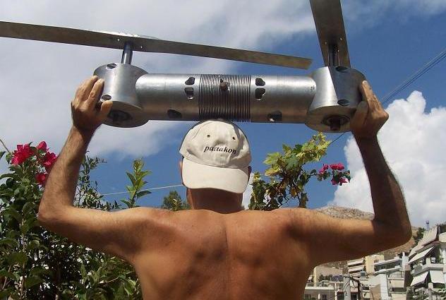
Think that the lift force and the centrifugal force that act on the blades of a conventional propeller try to deform it to a wide-vee:

Erickson%20Air-Crane*600.jpg?v=1

In the above photo the blades move on a wide cone, not on a plane.
Without the lift forces on the blades, the centrifugal forces would make the blades to move on a plane.


I think you will enjoy the youtube video https://m.youtube.co...h?v=E81KQ7u3-7s

0.jpg

The (water) Flying Board (shown in my last post), the JetPack of the above video and the pattakon Portable Flyers have some common characteristics:

they are rid of vibrations,

they are rid of the need for providing some “reaction torque”,

their gyroscopic rigidity is eliminated,

they are based on a force that can "instantly" and effortlessly be vectored towards the desirable direction,

they are based on a pure manual control wherein the eyes, the brain and the body of the rider are the sensing and controlling mechanisms.


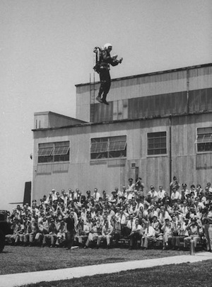
Quote from the Internet for the JetPack (or Bell Rocket Belt):

“The pack with its fuel weighed 125 lb (57 kg).”

“On 17 February 1961, the pack veered sharply, reaching the end of the safety tether, which then broke, causing the Moore (remark: he is the inventor of the JetPack) to fall approximately 2.5 meters, breaking his kneecap. He could no longer fly. Engineer Harold Graham took over as test pilot and testing resumed on 1 March. He then carried out 36 more tethered tests which enabled them to achieve stable control of the pack”

“On June 8, 1961, Harold Graham demonstrated Bell's "portable Army rocket" for the first time to an incredulous public. The flight saw Graham fly over a truck at a height of 15 feet landing 150 feet away after 14 seconds of air time. Nevertheless, the "ear-splitting" flight was described by the New York Times as "short but spectacular." By December 1961 Bell's 100-pound rocket belt would carry a man as high as 35 feet or a distance of 368 feet when barely skimming the ground.”

Jetpack_first_public_flight_300pxl.jpeg

“In the course of testing maximums of duration and distance were achieved: duration 21 seconds; range 120 m; height 10 m; speed, 55 km/h.”

“Before the flight the timer is set for 21 seconds. When the pilot turns the handle for the takeoff, the timer begins counting and will give second-by-second signals to a buzzer in the pilot's helmet. In 15 seconds the signal becomes continuous, telling the pilot that it is time to land.”

“The pack's pilot wears protective overalls made of thermal resistant material, since the exhaust jet and the engine's pipes are very hot.”

“However, the army was disappointed. The maximum duration of flight of the rocket pack was 21 seconds, with a range of only 120 m. A large contingent of service personnel needed to accompany the rocket pack. During flight 5 U.S. gallons (19 liters) of hydrogen peroxide was expended.
In the opinion of the military, the "Bell Rocket Belt" was more a spectacular toy than an effective means of transport.”

End of quote


If Moore was carrying, during the JetPack tests wherein he broke his kneecap, not 57Kp but less than 20Kp?

Compare the “freedom” offered by the JetPack and by the (water) Flying Board: their maximum height of flight is a dozen meters, their maximum range is a few dozens of m.

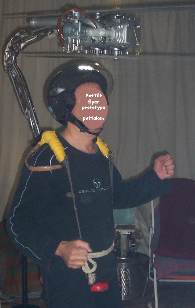
The pilot of the Portable Flyer needs not “to wear protective overall made of thermal resistance material” because the downwards moving air is not hot. He can fly without wearing a shirt, if he likes so, taking a few more grams of fuel with him for longer flights.

As you see in the (GoFast) JetPack video, there is neither a “structure”, nor seat, nor “foot rest”.

Quote from http://www.pattakon....pattakonFly.htm :

“What a man needs, in order to fly, is neither a vehicle, nor sensors, nor servomechanisms, nor control units, nor transmission shafts, nor differentials, nor gear-boxes, not even a seat.

What a man does need, in order to fly, is power provided in a true neutral and manageable way. The body is: the vehicle and the sensors and the control unit and the servomechanisms and the landing system, just like the bodies of the birds, bats and bugs”


All the fight for a successful Portable Flyer is to cut the weight down and to have adequate and manageable power.

For instance:

How can you synchronize – with the minimum weight and complication - the two counter-rotating crankshafts of the PatATi Opposed Piston Portable Flyer?
Can you avoid completely the exhaust?
Can you avoid completely the intake manifold?

Everything is around the weight reduction, because every gram of mass counts (weighs a lot) in a Portable Flyer.


If with a Portable Flyer you can go fast (with, say, 250Km/h), at really long distances (say, 300Km range) and with low fuel consumption, the world changes.

Thanks
Manolis Pattakos

Edited by manolis, 26 October 2014 - 03:19.


#81 TDIMeister

TDIMeister
  • Member

  • 318 posts
  • Joined: January 06

Posted 06 November 2014 - 17:52

Damn, looks like the inside of a Rolex watch!


How different, how very different, from the Bristol sleeve valve drive gear:


Bristol%20Hercules%20XVI%20No1%2006.JPG


#82 manxmog

manxmog
  • New Member

  • 2 posts
  • Joined: November 14

Posted 05 December 2014 - 22:03

Does anyone know how the balance factor for  the crankshaft of a radial engine is calculated?

Or is there a simple technique for balancing?


#83 manolis

manolis
  • Member

  • 935 posts
  • Joined: May 03

Posted 06 December 2014 - 05:02

Hello Manxmog

If you cannot find something else,
you can use the visual basic program at http://www.pattakon....atAT/Radial.exe (it requires windows).
Pressing the c key on the keyboard, the vector of the total inertia force from all reciprocating masses appears.

If you know visual-basic, you can “play” with the code of the program.

On the other hand, the 1/2 balance factor (i.e. you replace all the reciprocating mass m, comprising the pistons, the piston pins, the piston rings and the upper part (about 1/3) of the connecting rods, by a mass m/2 at the center of the crankpin) seems a good first approach.

Thanks
Manolis Pattakos

#84 manxmog

manxmog
  • New Member

  • 2 posts
  • Joined: November 14

Posted 06 December 2014 - 19:57

Thanks Manolis, that program is a lot of fun.  Where can I get the source code?


Jon


#85 manolis

manolis
  • Member

  • 935 posts
  • Joined: May 03

Posted 07 December 2014 - 06:27

Hello jon

The code in text format is at

http://www.pattakon....T/Radial_VB.txt


You may need the files:

http://www.pattakon....T/Radial_VB.FRM

and

http://www.pattakon....T/Radial_VB.frx

Thanks
Manolis Pattakos