Jump to content


Photo
- - - - -

CNC machining a crankshaft from scratch


  • Please log in to reply
19 replies to this topic

#1 Magoo

Magoo
  • Member

  • 3,731 posts
  • Joined: October 10

Posted 20 November 2014 - 16:05

This little video won't be tremendously earth-shattering for you lot.... a little old hat, perhaps... machining a crankshaft from a raw billet (a round, technically). The tool paths and other items are interesting...


...also, take a look at the crankshaft itself. Hmmm. Discuss. 


Video: See a crankshaft created from a raw steel billet | Mac's Motor City Garage.com 


9hoDBS.jpg


Advertisement

#2 Greg Locock

Greg Locock
  • Member

  • 6,370 posts
  • Joined: March 03

Posted 20 November 2014 - 21:53

Don't the journals need grinding?


#3 desmo

desmo
  • Tech Forum Host

  • 29,560 posts
  • Joined: January 00

Posted 20 November 2014 - 22:05

Hypnotic to watch. Is each rod journal a completely different design?  Looks so, anyone need a 50kg paperweight?


#4 Magoo

Magoo
  • Member

  • 3,731 posts
  • Joined: October 10

Posted 20 November 2014 - 23:50

Hypnotic to watch. Is each rod journal a completely different design?  Looks so, anyone need a 50kg paperweight?


Indeed. High-end salesmens' sample. 


#5 imaginesix

imaginesix
  • Member

  • 7,525 posts
  • Joined: March 01

Posted 21 November 2014 - 01:42

As per the comments, the video is comprised of segments shot during the machining of different cranks.

#6 gruntguru

gruntguru
  • Member

  • 7,642 posts
  • Joined: January 09

Posted 21 November 2014 - 02:56

If you look at the still image in post #1 you can see it is a demonstration workpiece - different journal and counterweight styles and sizes to demonstrate a number of processes and the flexibility of the operation. Either that or it is a crank designed for a very strange widget - inline IC engine driving integral VEE recip compressor?


Edited by gruntguru, 21 November 2014 - 02:57.


#7 Canuck

Canuck
  • Member

  • 2,389 posts
  • Joined: March 05

Posted 21 November 2014 - 04:21

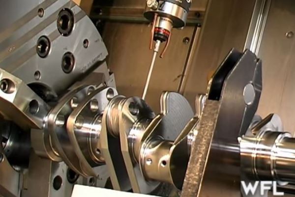
I used to run a Doosan MX-2000ST 9-axis machine. These mill-turn machines are amazing bits of kit. With essentially two parallel control systems, you could actually make two different parts in the machine at the same time. Our machine was a twin-spindle unit with a 24-station turret and 60(?, 100?) station tool chain for the milling head. It was best executed for parts that had complex relations and tight tolerances. The downside to a machine with this kind of ability is the corresponding complexity in setup and 1st-off parts. It would often take us a day to get a 100% 1st-off, but then it was just a matter of watching it spit complicated parts off with no 2nd setups, no secondary milling operations, just deburr and put on the production line. I'd like to see a cylinder head machined in one - cranks are just round things.

The machine I ran was demon-possessed for the better part of two years. It would happily churn out perfect parts and then randomly crash, destroying both the part and inevitably the much more expensive tooling. A misunderstanding with the manufacturer (no problem to remove the backup batteries on the control!) led to having to rewrite the entire ladder system, which is essentially the interface between the CNC control (Fanuc) and the machinery. That exorcised the demon and from that point on it ran like a champion. When we suffered a terminal "roof top consolidation" they were afraid to take that beast with them and it landed in a turbine blade operation in Bangor, Maine where it continues to operate to this day (afaik).

#8 Wuzak

Wuzak
  • Member

  • 8,508 posts
  • Joined: September 00

Posted 21 November 2014 - 04:53

I'd like to see a cylinder head machined in one - cranks are just round things.


How about a cylinder block?


#9 bigleagueslider

bigleagueslider
  • Member

  • 1,235 posts
  • Joined: March 11

Posted 21 November 2014 - 05:10

One of the cranks shown in the video is a split-pin design for a V6 engine.  The journals get finish ground after nitriding. The part where the timing chain sprocket teeth were being hobbed directly on the crank was pretty impressive. Not an easy thing to do. The material removal rate of this machine was also pretty impressive for an alloy steel part. This machine must have pretty high spindle horsepower.


#10 gruntguru

gruntguru
  • Member

  • 7,642 posts
  • Joined: January 09

Posted 21 November 2014 - 05:42

One of the cranks shown in the video is a split-pin design for a V6 engine.

You mean one of the journals - look at the still image in Post #1 and you will see single, shared and split crankpin journals all on the one workpiece (I hesitate to call it a crankshaft).


#11 Lee Nicolle

Lee Nicolle
  • Member

  • 11,069 posts
  • Joined: July 08

Posted 21 November 2014 - 07:55

One of the cranks shown in the video is a split-pin design for a V6 engine.  The journals get finish ground after nitriding. The part where the timing chain sprocket teeth were being hobbed directly on the crank was pretty impressive. Not an easy thing to do. The material removal rate of this machine was also pretty impressive for an alloy steel part. This machine must have pretty high spindle horsepower.

I too noticed the 1/4 cuts. Must be very good material. Not just the machine. 

I too thought it was a couple of cranks. One a staggered pin and one a normal single crankpin.

The flywheel bolts being about 14mm course thread was a bit weird too.


#12 Greg Locock

Greg Locock
  • Member

  • 6,370 posts
  • Joined: March 03

Posted 21 November 2014 - 09:51

I was a bit surprised to see the swarf coming off as a long coil. Although that is a satisfying thing to do when running a manual lathe, in a manufacturing environment it is not encouraged, as the coils whip around and jam things and are buggers to handle.


#13 Canuck

Canuck
  • Member

  • 2,389 posts
  • Joined: March 05

Posted 21 November 2014 - 13:22


Chip breaking in slow motion.

#14 bigleagueslider

bigleagueslider
  • Member

  • 1,235 posts
  • Joined: March 11

Posted 23 November 2014 - 03:59

I was a bit surprised to see the swarf coming off as a long coil. Although that is a satisfying thing to do when running a manual lathe, in a manufacturing environment it is not encouraged, as the coils whip around and jam things and are buggers to handle.

The material coming off the cutter is definitely a problem if not broken. Spirals of unbroken material is typical when machining hard steels. These spirals are mostly created when there is no interruption at the interface between the cutter and material, such as with drilling or turning operations. This is the reason you see NC drilling of deep holes performed by "pecking".


#15 Magoo

Magoo
  • Member

  • 3,731 posts
  • Joined: October 10

Posted 23 November 2014 - 04:24


Chip breaking in slow motion.


Mesmerizing. Nice score too. 


#16 bigleagueslider

bigleagueslider
  • Member

  • 1,235 posts
  • Joined: March 11

Posted 27 November 2014 - 05:27

Watched the video and it was indeed very interesting. Almost looks like some sort of SEM was used to record the images. The part of the video around the 4 min mark was very interesting in how it showed the material well ahead of the cutter edge being sheared apart.


It would be neat to see how much energy is transferred from the cutter to the material in this process. One thing you always notice in the material machined from alloy steels is their color, which is usually light brown or blue due to the amount of heat produced in them from machining. With materials like stainless steel or titanium, the heat and stress inparted by the cutter can work harden the part surface, making it more difficult to machine further. Often it is not possible to cool the cutter interface sufficiently using conventional fluids. A friend of mine actually did his masters thesis on using liquid CO2 to cool very high speed cutting tools when machining difficult materials like titanium or Inconel.


#17 kikiturbo2

kikiturbo2
  • Member

  • 869 posts
  • Joined: December 04

Posted 27 November 2014 - 09:28

yeah, looks like a SEM... must have been interesting making a vacuum chamber for that... Also, the high speed scanning is not something I see.... Been a long time since I worked for Philips EO / FEI on electron microscopes though.. :)


#18 gruntguru

gruntguru
  • Member

  • 7,642 posts
  • Joined: January 09

Posted 27 November 2014 - 22:40

Fascinating. Around 4:00 - 4:30 with a large built up edge you can see the tool move out of frame periodically as the force increases.


#19 imaginesix

imaginesix
  • Member

  • 7,525 posts
  • Joined: March 01

Posted 27 November 2014 - 22:51

yeah, looks like a SEM... must have been interesting making a vacuum chamber for that... Also, the high speed scanning is not something I see.... Been a long time since I worked for Philips EO / FEI on electron microscopes though.. :)

I coulda made that same video using some plasticine and a wood wedge :)


Advertisement

#20 Magoo

Magoo
  • Member

  • 3,731 posts
  • Joined: October 10

Posted 27 November 2014 - 23:11

I coulda made that same video using some plasticine and a wood wedge :)


I had the same thought. I was also reminded of cutting beef. Perhaps I was hungry at the moment.