Hello Bigleagueslider.
You write:
“gg- The current Achates OP design does not use a crosshead type piston. It uses a journal type bearing at the conrod big end and a clever tilting plain bearing wrist pin similar to that used on the Napier Nomad. And all of the OP concepts shown above by Manolis appear to use numerous conrods and crank throws for each piston, which is no less complicated than a conventional OP configuration.
Quote from the “Rolling thrust bearing constructions” US8,807,112 patent:
BACKGROUND
The field relates to thrust bearings, particularly to rolling thrust bearings. The field also relates to rolling thrust bearings for pistons used in internal combustion engines. More particularly, this field covers piston rolling thrust bearing constructions for coupling a piston to connecting linkage of an internal combustion engine.
Opposed-piston diesel engines have an acknowledged potential for superior performance according to standard measures of output power and fuel efficiency. For example, the Rootes-Lister diesel engine (also known as the Commer `TS3` diesel) illustrated in FIG. 1 advanced two-stroke engine construction by way of an engine configuration which included three pairs of opposed pistons driving a single crankshaft. Each piston was coupled to a respective crankpin by a rocker assembly. Each rocker assembly included a rocker arm pivoted between two ends, a piston rod connected to a first end of the rocker arm and to a wrist pin located inside the piston, and a connecting rod connecting the second end of the rocker arm to a crankpin. All of the rocker assemblies were identical, with each rocker arm end being pivoted to the engine frame. The architecture of the rocker assemblies significantly reduced side forces acting on the pistons, thereby making the engine very durable. However, at least one construction feature severely compromised the performance of the Rootes-Lister engine.
(A1)
In the Rootes-Lister engine wrist pins ("gudgeon" pins, UK) were mounted inside the pistons, which limited the size of the bearings for the pins, and therefore the ultimate load bearing capacity of the pistons. As a result of this and other constraints, the engine was limited to operating at very low power levels (about 38 HP/liter).
Examples of opposed piston engine constructions that remove wrist pins from inside pistons are found in Great Britain Patent 558,115 and in U.S. Pat. Nos. 7,156,056 B2 and 7,360,551 B2. In each case, there is no articulation of the piston-to-crankshaft linkage that is internal to the piston. Instead, joints external to the pistons couple the linear motions of the pistons to each of a pair of crankshafts located above and below the cylinders. The axes of the crankshafts lie in a plane that is normal to the axes of, and that bisects, the cylinders.
(A2)
Both crankshafts are connected to each pair of opposed pistons through multiple connecting rods. Consequently, very close tolerances must be maintained during manufacturing to avoid, or at least mitigate, misalignment between the connecting rods and external wrist pins that could result in undesirable side forces exerted on the pistons. A consequence of coupling both crankshafts to the single wrist pin of each piston is an over constraint condition whereby unequal elastic deformation of the coupling components can lead to significant deflection of the wrist pin in a direction orthogonal to the piston motion that produces undesirable side forces acting on the piston.
Accordingly, the potentially high power levels in two-stroke, opposed-piston engines have not been fully achieved by single crankshaft constructions with rocker assemblies because wrist pins are located inside the pistons. However, dual-crankshaft constructions in which the wrist pins have been removed from, and relocated outside of, the pistons have also not achieved full power potential due to side forces resulting from over constraint of the wrist pins.
. . .
End of quote.
Look at the PatOP Opposed Piston engine:
and then look at the Commer TS3:
With a little imagination, the PatOP can be seen as resulting from a Rootes-Lister Commer TS3 after:
eliminating the massive rocker arms with their pivots,
and after eliminating the secondary connecting rods with the pivot pins between the rocker arms and the secondary connecting rods,
and after rearranging the remaining parts.
Calculate the friction saving and the weight saving (the casing included) and the cost saving related with the eliminated parts; calculate also the space required for these parts.
By the way, the PatOP has a built-in piston-type scavenging pump, while the Commer TS3 needs an external scavenging pump comparable in size with the rest engine.
Nevertheless, the Commer TS3 Rooters is regarded by Achates Power as a promising architecture for Opposed Piston Diesels and it is used as the basis for their abovementioned US8,807,112 patent / “improvement”.
The US7,156,056 mentioned in paragraph (A2) is the Achates Power Opposed piston with the two side crankshafts and the hyperstatic architecture:
Count the number of connecting rods per piston; is it 3 or 4?
According the paragraph (A2) above, the problem is not the complexity of this design, it is that “a consequence of coupling both crankshafts to the single wrist pin of each piston is an over constraint condition whereby unequal elastic deformation of the coupling components can lead to significant deflection of the wrist pin in a direction orthogonal to the piston motion that produces undesirable side forces acting on the piston.”
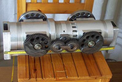
If you still think the PatOP has too many connecting rods per piston, what about the “father” of PatOP, the OPRE opposed piston wherein each piston has one only connecting rod (actually a pulling rod providing more than 30% additional dwell at combustion TDC):
OPRE (Opposed piston Pulling Rod Engine) has its two crankshaft close to each other, making easier their synchronization:
In the paragraph (A1) Achates Power writes: “In the Rootes-Lister engine wrist pins ("gudgeon" pins, UK) were mounted inside the pistons, which limited the size of the bearings for the pins, and therefore the ultimate load bearing capacity of the pistons.”
The wrist pins of the OPRE engine are located outside the pistons, at the other side of the crankshaft wherein the piston performs the scavenging.
Obviously, you can use (in the OPRE and in the PatOP opposed Piston engines) as big wrist pin as you like.
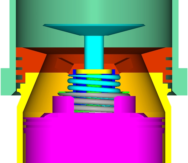
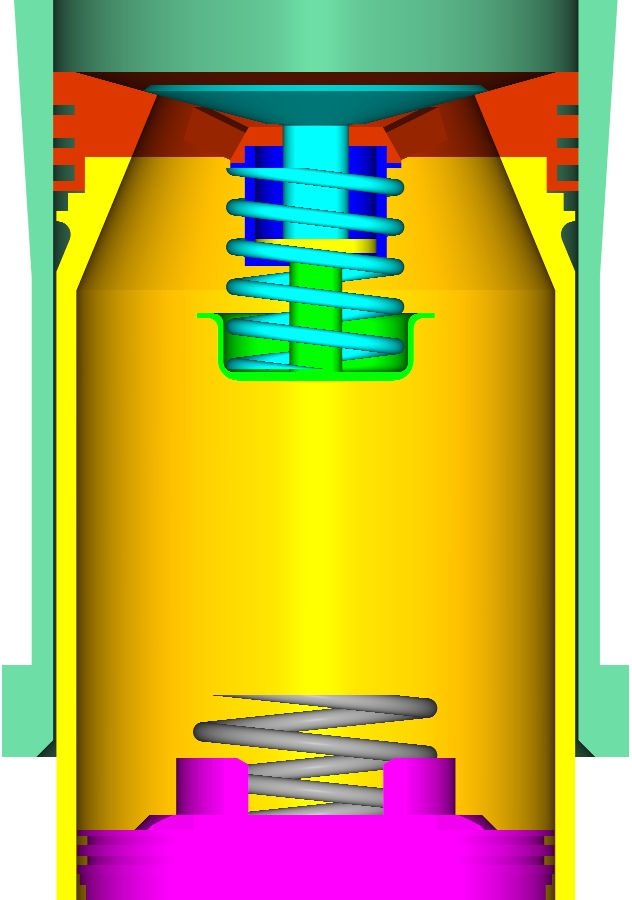
By the way, think how much better is the lubrication (we call it “four-stroke-like lubrication) in the OPRE and PatOP Opposed Piston engines:
you have plenty of oil at the cool and rid-of-ports side of the cylinder wherein the thrust loads are taken, leaving – by oil scraper rings – only the required quantity of lube to pass and lubricate the piston rings at the combustion side.
By the way, what is the solution for the lubrication issue of the conventional Opposed Piston design of the Achates Power?
With their “crosshead” / double side-crankshaft arrangement the 0.1gr/kWh was reasonable; what is the specific lube consumption they achieve now with their conventional arrangements?
I know that you mention, in your response to Gruntguru, not the “Rolling Thrust Bearing” of Achates Power, but the “clever tilting plain bearing wrist pin similar to that used on the Napier Nomad” used in the conventional – for the rest – Opposed Piston engine of Achates Power:
Is this the most advance “innovation” / “improvement” you saw in Achates Power web site?
And what is the difference of this titling plain bearing than that of the Napier Nomad made between 1949 and 1955?
If you look deeper, you can see at the PAIR that the USPTO is not accepting that utilizing the well-known “titling plain bearing of Napier Nomad” in an Opposed Piston engine has an inventive step (or is not obvious to a skilled in the art).
The controversy between Achates Power and the USPTO Examiner is under progress.
Quote from Achate Power US 20120073526 application publication:
In other aspects of two-stroke, opposed-piston engine construction, the nature of the operating cycle results in the uninterrupted application of compressive loads on bearings in the piston-to-crankshaft connecting linkages. These non-reversing loads prevent the separation of bearing surfaces, which blocks the flow of lubricant therebetween and limits the durability of such bearings.
(B1)
As a result, during opposed-piston engine operation a continuous compressive load is exerted on wristpin bearings throughout the operating cycle. It is therefore desirable to provide piston constructions with the capability of articulating the piston with a connecting rod by way of a bearing construction that separates bearing surfaces for provision of lubrication during the operational cycle of an opposed-piston engine.
. . .
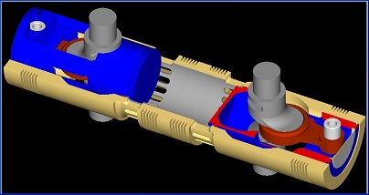
Coupling Mechanism Construction: As seen in FIGS. 6 and 7, there is no wristpin in the construction of the coupling mechanism 255. Instead, the bearing linking the piston 60 with the piston rod 254 includes two parts with complementarily-curved bearing surfaces. One bearing part 264p is joined to the back of the crown 252; the other bearing part 264r is formed on the end of the piston rod 254. Each of the bearing surfaces includes eccentric sections; together, the bearing pieces 264p and 264r constitute a biaxial, or eccentric, slipper bearing. Such a bearing construction is known: see, for example, "Napier Nomad", FLIGHT, 30 Apr. 1954, pp. 543-552. In the slipper bearing, each bearing surface is constituted of three lengthwise sections: two outer sections and a center section. On the bearing piece 264p, the three sections are outer sections 265s and center section 265c. On the bearing piece 264r, the three sections are outer sections 266s and center section 266c. In each bearing surface, the two outer sections are coaxial with each other and displaced from a centerline of the bearing. The center section of each bearing surface is displaced in the opposite direction from the bearing centerline. Since the bearing therefore has a first axis shared by the side sections and a second axis for the center section, the bearing is said to be "biaxial". The two displacements may or may not be equal, depending on the oscillating motion of the piston rod 254. Thus the two axes are eccentric in relation to each other. In an exemplary application for bearings of 50 to 100 mm in diameter this eccentricity is on the order of 0.1 to 1 mm. The eccentricity of the bearing provides a mechanical lifting of one bearing surface from off of the journal surface on alternate sides as the piston rod 254 oscillates from side to side. This provides the separation in the bearing surfaces of the coupling mechanism 255 so that pressurized oil, fed from a drilling 267 in the center of the piston rod 254, can enter in the void between the surfaces. The bearing surface on the bearing piece 264r is located furthest away from the piston crown to allow for lower lubricant operating temperatures to keep the oil viscosity higher and provide for a greater minimum oil film thickness (MOFT) when the squeeze film develops.
End of quote.
Let see whether the “biaxial, or eccentric, slipper bearing” of Napier Nomad is necessary in the PatOP or in the OPRE engine.
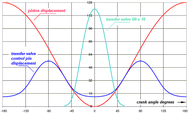
The reverse arrangement of the connecting rod shifts the maximum piston acceleration to the BDC (i.e. to the dead center wherein the scavenging happens).
75 crankshaft degrees after the BDC an inertia deceleration starts acting on the piston. 110 crankshaft degrees after the BDC (i.e. 70 crank degrees before the combustion TDC) this inertia deceleration becomes about half of the maximum inertia acceleration of the piston.
Let’s take a piston having 80mm diameter, 80mm stroke, 1Kp weight (including the wrist pin and the upper 1/3 of the connecting rod).
At 3,000rpm the maximum inertia force is 530Kp (at BDC), the decelerating force at 90 degrees before the TDC is 150Kp, the decelerating force at 80 degrees before the TDC is 200Kp.
With 50cm2 piston area, if the pressure inside the cylinder is no more than 3bar at 90 degrees, or no more than 4 bar 80 degrees before the combustion TDC (CTDC), the wrist pin plays from side to side in its bearings, allowing oil to lubricate it.
At higher revs (and/or heavier piston) the lubrication of the wrist pin is easier because it “plays” from side to side into its bearings.
At very low revs, you need some pressure )but not high) to force the oil pass between the wrist pin and its bearing.
The OPRE and the PatOP engines match better with shorted connecting rods (smaller con-rod to stroke ratios). This causes the wrist pin to oscillate inside its bearings at a wider angle. And softens, a lot, the wrist pin lubrication issue.
If the above are confusing, let me further explain.
It would be nice and useful if you could post a photo or drawing or animation of the top engine of Achates Power (i.e. of the engine they currently think is their best offer), because I am confused.
Thanks
Manolis Pattakos


