Hello BigLeagueSlider
In the SKF general catalogue, after the page “Friction / Estimating the frictional moment” (shown in my last post), there are 15 pages dedicated to the detailed frictional moment analysis.
But the general approach of SKF (a big and reputable rolling bearing manufacturer) is:
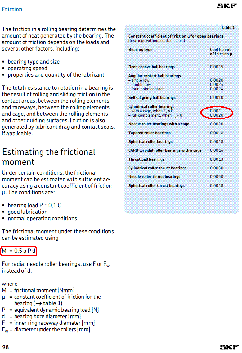
“The frictional moment is proportional to the working diameter of the rolling bearing and depends heavily on its architecture (constant coefficient of friction).”
It is a “rule of thumb”, not a law.
There are conditions wherein the rolling friction prevails, others wherein the sliding friction is the big part, other wherein the viscous friction gets more important, and so on.
However the above rule of thumb is still a good approach.
For instance, doesn’t it seem reasonable that the friction is, more or less, proportional to the working diameter of the rolling bearing?
The various “friction” generating processes create friction forces; these friction forces acting on a bigger eccentricity (as happens in a bigger diameter roller bearings) cannot help creating heavier “frictional moment”.
In my last post I forgot to mention that with the PatRoller you can either increase the load carrying capacity of a specific rolling bearing, or you can achieve the same load carrying capacity by modifying a rolling bearing of smaller working diameter (i.e. of smaller friction according the above “rule of thumb”).
With an additional external ring, the smaller diameter PatRoller bearing can be mounted in the original envelope.
You write:
“The information from SKF you posted above regarding the use of a simple Mu value to estimate losses is not a good approach for most situations, since losses are significantly affected by velocity of the bearing components.”
Isn’t, more or less, the velocity of the bearing components proportional to the working diameter of the roller bearing?
You write:
“Also, one issue I saw with the Pat Roller concept posted above is that it does not appear that it can be assembled, at least as shown.”
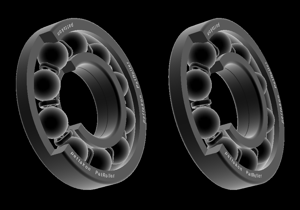
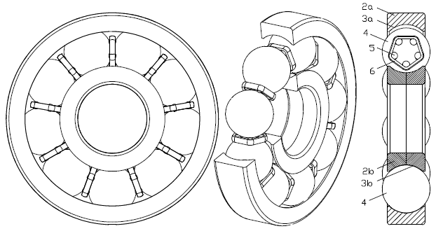
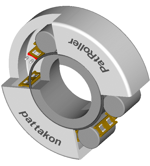
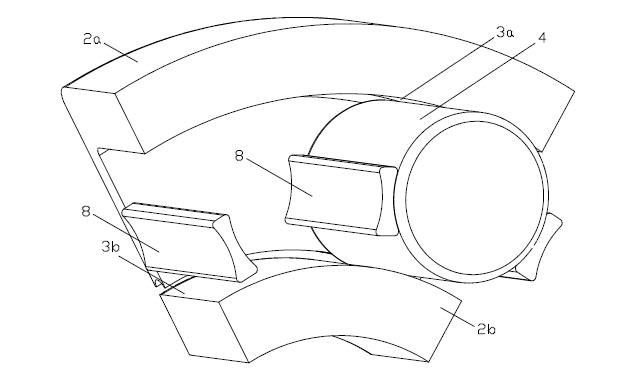
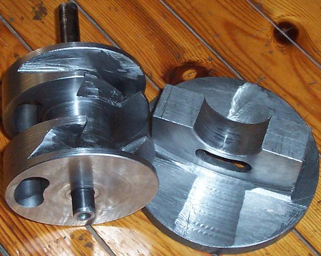
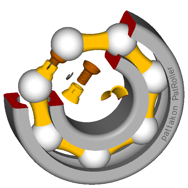
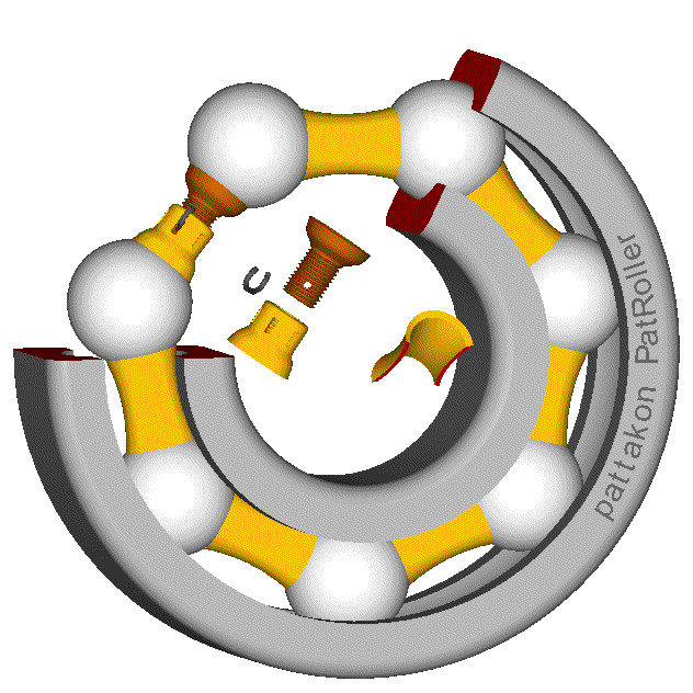
Regarding the assembly of the “single-piece ring” PatRoller ball bearings (hello Gruntguru):
(sorry but I have to post the drawings again and again), things are quite simple:
The spacers have a small elasticity (this is why they are shown with cuts / slots).
All the balls and spacers, except one spacer, are inserted easily between the two bearing rings (i.e. between the outer and inner bearing rings, each one being a single piece).
To install the last spacer between its two neighbor balls, these balls are pressed, by a tool, away from each other; the already installed spacers are elastically deformed allowing the rest pairs of balls to slightly approach each other increasing substantially the distance of the balls at the ends of the last spacer.
After the insertion of the last spacer the balls are freed and the ball bearing is ready to work.
If, for some reason, the ball bearing is to be disassembled, all the difficulty is the removal of a spacer. The neighbor balls of the spacer are pressed away from each other, the rest spacers are elastically deformed allowing the rest pairs of balls to slightly approach each other etc.
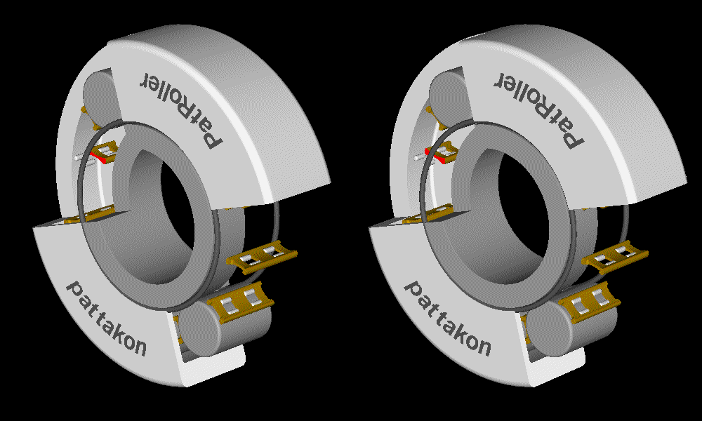
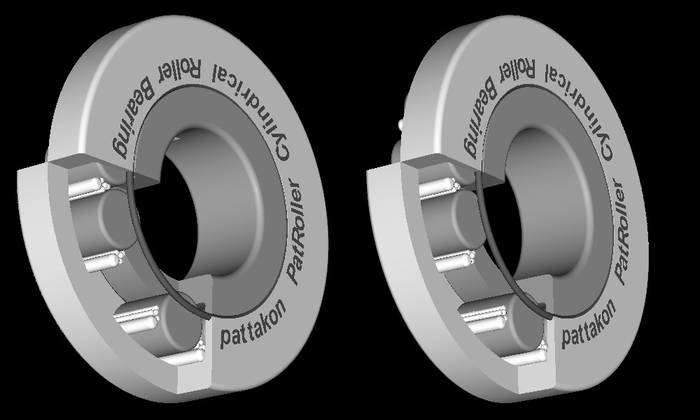
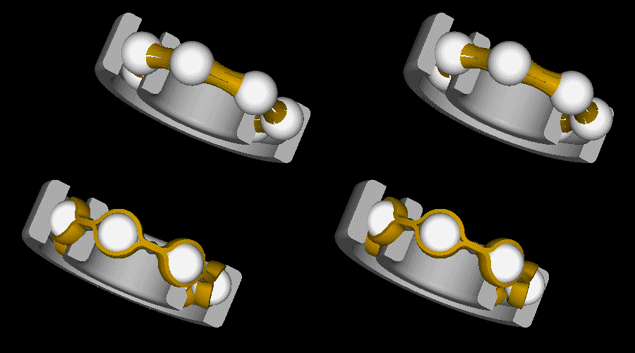
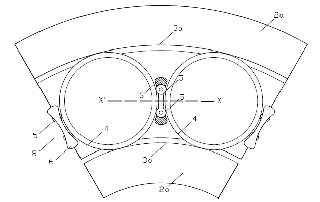
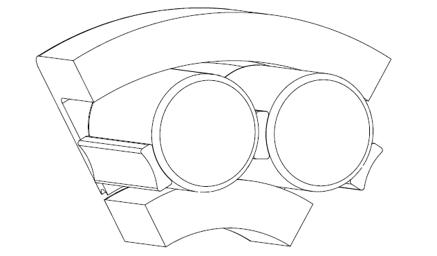
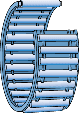
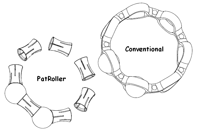
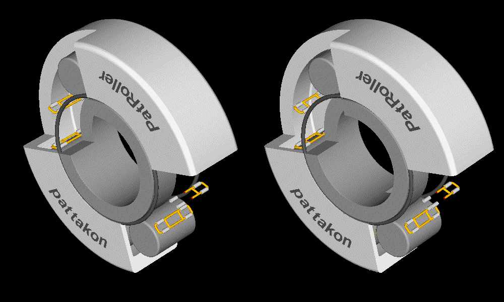
But I think you mean the assembly of a cylindrical PatRoller bearing like the one in the following stereoscopic animation:
There are various ways to do the assembly.
A first way:
The last spacer is different (is the “master spacer”); it comprises two pieces secured / locked to each other (just like the master link of the chain of a bicycle).
A second way:
The small elasticity of the spacers is exploited.
The assembly is more than easy before the last spacer.
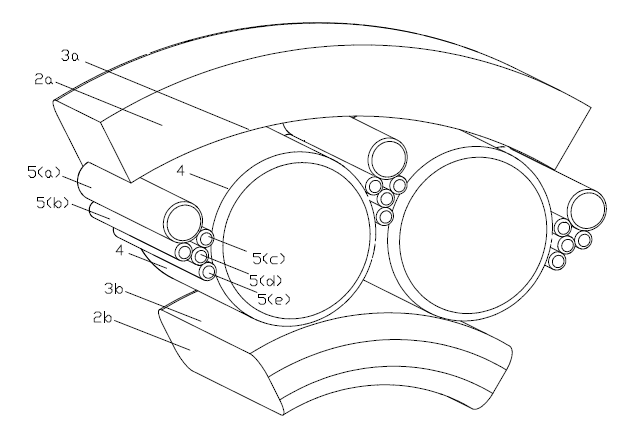
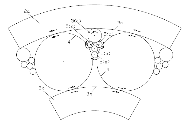
In order to insert / install the last spacer, its neighbor cylindrical rollers are pushed away (along the periphery of the external bearing ring) from each other; each pair of neighbor cylindrical rollers abuts on the needle rollers of the spacer between them, and tries to push away the needle rollers from each other; the needle rollers abutting on the spacer push the spacer to slightly expand. Due to the big number of spacers, the distance of the two cylindrical rollers wherein the last spacer is to be inserted increases substantially allowing the last spacer with its needle rollers to pass through the gap and get installed. Then the cylindrical rollers are released and the cylindrical rolling bearing is ready to work. The spacers are trapped between the cylindrical rollers.
For the disassembly, the reverse procedure can be followed.
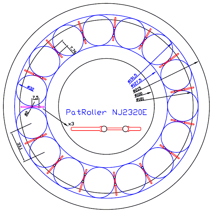
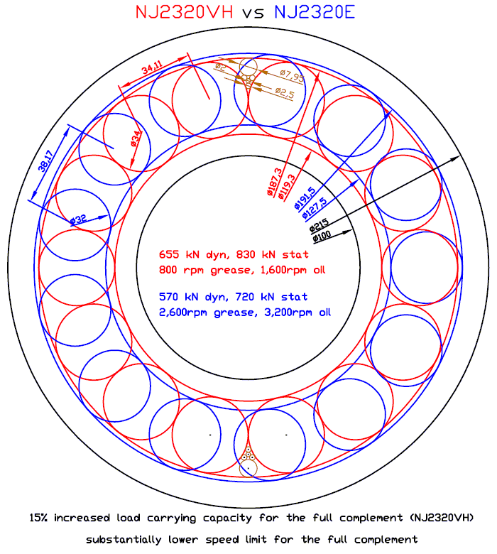
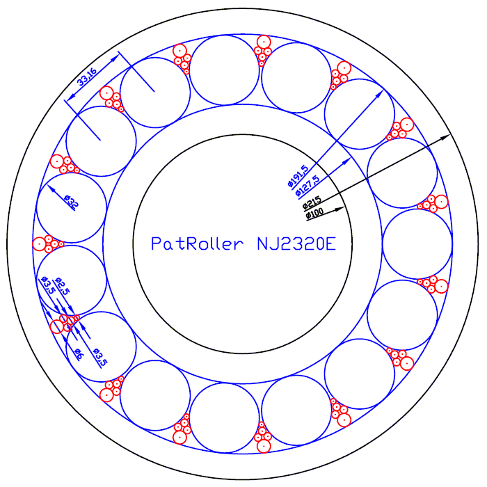
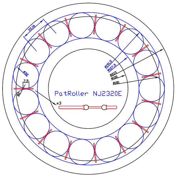
The above drawing shows the moment the last spacer (shown by purple color) is inserted.
Compare the drawing with the previous posted (both for the NJ2320E).
Each of the rest spacer has to lengthen by 3.5% between its needle rollers during the assembly of the last spacer.
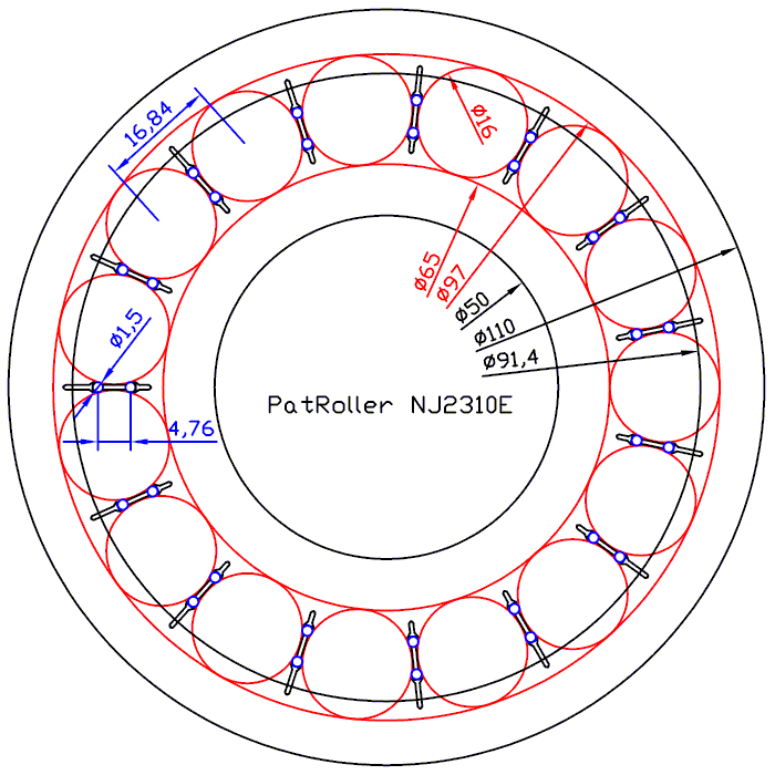
And here is the PatRoller NJ2310E during assembly:
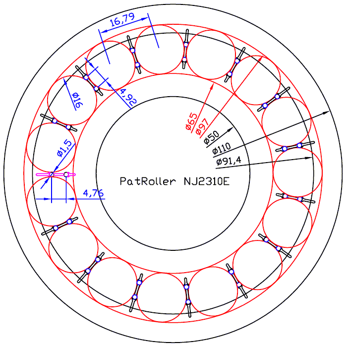
In order the gap between the neighbor cylindrical rollers of the last spacer to open at 1.5mm (and so to allow the spacer with the 1.5mm diameter needle rollers to pass), each one of the rest spacers must expand a little so that the distance of its two neighbor cylindrical rollers to reduce by 0.05mm (14*0.05=0.7 and 0.7+16.8=17.5=16+1.5 )
A third way:
The external bearing ring is heated at, say, 225 degrees Celsius, the rolling elements are cooled at, say, –75 degrees Celsius (dry ice). The thermal expansion / contraction of the parts makes the gap between the last pair of cylindrical rollers adequate for the last spacer to pass (the calculations are easy; if there is interest, I can explain why 300 deg Celsius temp difference is adequate for the assembly of the PatRoller NJ2320E). As the temperature difference between the parts weakens / fades, the roller bearing cannot disassemble.
To disassemble the rolling nearing, a spacer needs to break / to be sacrificed.
A fourth way:
It combines the second and the third ways. With the external bearing ring hot, the required elastic expansion of the spacers reduces.
A fifth way:
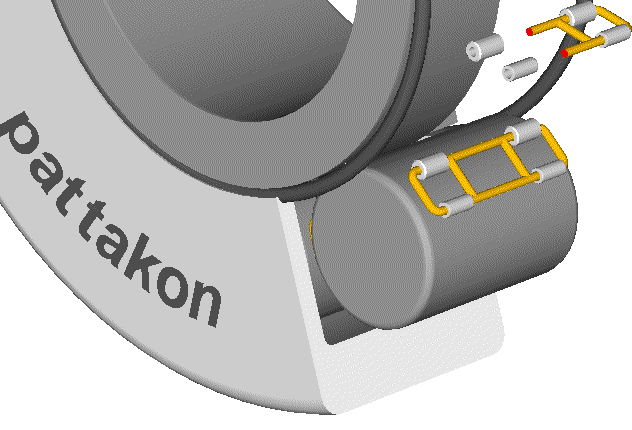
Instead of heating the external ring, a high pressure can be applied on its inner space. You install all components - except the last spacer – at their positions into the external ring (the last spacer is slightly pushed between its neighbor cylindrical rollers but the needle rollers cannot pass through the gap).
Then you put two sealed covers at the sides of the external ring.
Then you fill the space into the external ring with oil and increase the oil pressure.
The external ring expands elastically, the gap at the last spacer increases and the last spacer “slides” between its neighbor rollers.
Thanks
Manolis Pattakos
Edited by manolis, 01 October 2015 - 04:32.


