Jump to content


Photo
- - - - -

PatTol (like VTOL) unconventional helicopter


  • Please log in to reply
16 replies to this topic

#1 manolis

manolis
  • Member

  • 935 posts
  • Joined: May 03

Posted 15 March 2016 - 04:16

Hello all.

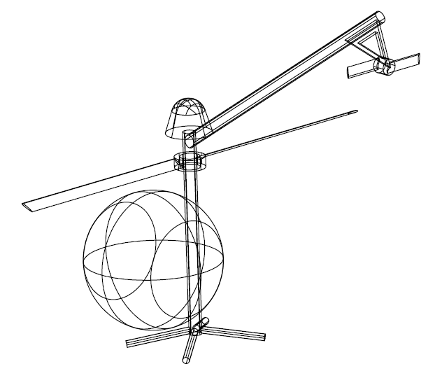
In a VTOL vehicle (like a helicopter, a Portable Flyer etc) an unconventional frame extending above any main rotors (those providing the lift) offers new opportunities in safety and architecture/design.

The main rotor of a conventional helicopter divides the space into an area above the main rotor and an area underneath the main rotor wherein the fuselage (or the load) is. The area above the main rotor is not accessible:
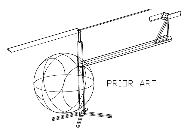
PatTol_3A.gif

In a PatTol helicopter:

PatTol_3B.gif

the frame extends (through the hollowed hub of the main rotor) into the area above the main rotor, providing support to auxiliary / safety equipment.

The deployment of a rescue parachute (stored, during the flight, into a cage secured onto the frame above the main rotor) is rid of the obstacle of a rotating, above it, rotor:
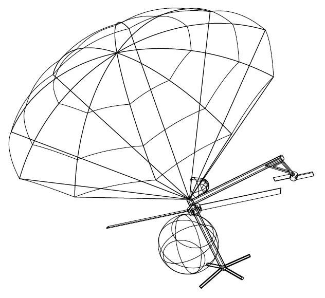
PatTol_4.gif

A tail boom arranged in the area above the main rotor and having a tail rotor at its end, gives new design and safety options.


In conventional "contra-rotating" helicopter:
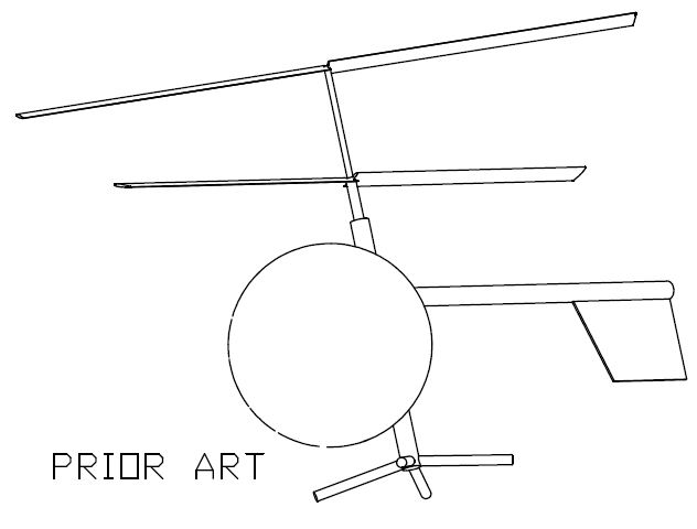
PatTol_11.gif

the support and driving of the top rotor is an issue. Also the control over the top rotor.

In a PatTol "contra-rotating" helicopter:
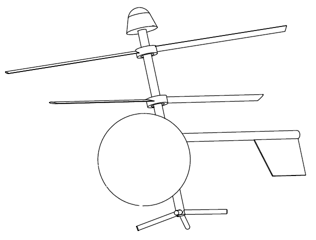
PatTol_12.gif

the support of the top rotor is easier and more robust / safe.
The engine(s) and the transmission can be arranged in the space between the contra-rotating rotors, or below the lower rotor, or even above the top rotor.
The fuel (for engines above the lower rotor) and the control (of engines and rotors) pass through the hollowed extension of the frame.
A rescue parachute can be stored in a cage secured at the top of the frame, above the top rotor.


In a PatTol Air-Crane:
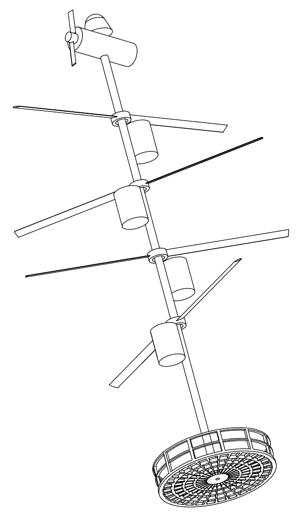
PatTol_5.gif

the frame is a long mast whereon several hollowed-hub rotors are rotatably mounted (with each having, preferably, its own motor and transmission). At the bottom of the mast is a basket (fuselage) for passengers, or for cargo.
The big diameter rotors provide the required lift, the top motor/propeller is for the propelling the air-crane.
A rescue parachute, at top, is for safe landing in case of emergency.
Simple, cheap, robust, lightweight and safe, it suits for air-cranes, for fire-fighting, for rescuing people trapped in hazardous areas etc.


The following PatTol airplane / helicopter (likewise the Osprey V22) uses a main propeller with hollowed hub.
The frame extends from the fuselage to the area above the main rotor, wherein a wing, with two propellers, is secured.
During a vertical take off, the propellers provide the required reaction torque, while most of the power is provided to the main rotor.
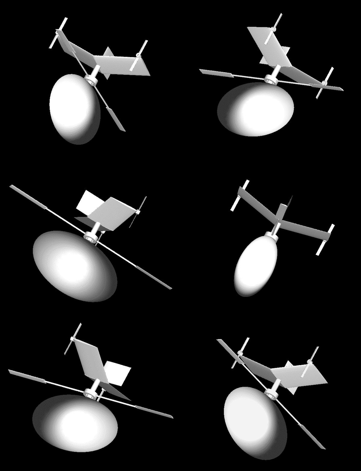
PatTol_10.gif

Progressively the power to the main rotor reduces and the power to the propellers increases (with the pitch of the propellers aligned properly). The vehicle accelerates horizontally with more and more of the required lift provided by the wing.
Later, power is provided exclusively to the propellers. The main rotor gets to a stall and is secured on the frame at a position minimizing the aerodynamic resistance and improving the stability of the vehicle.
Etc.

Thoughts?

Objections?

Thanks
Manolis Pattakos

Advertisement

#2 Kelpiecross

Kelpiecross
  • Member

  • 1,730 posts
  • Joined: October 10

Posted 15 March 2016 - 05:06


I like the idea of a rescue parachute for a helicopter. Otherwise I am not so sure.

#3 manolis

manolis
  • Member

  • 935 posts
  • Joined: May 03

Posted 17 March 2016 - 05:15

Hello all.

Today it was granted by the US-PTO the US 9,303,637 patent to the Tilting Valve engine.

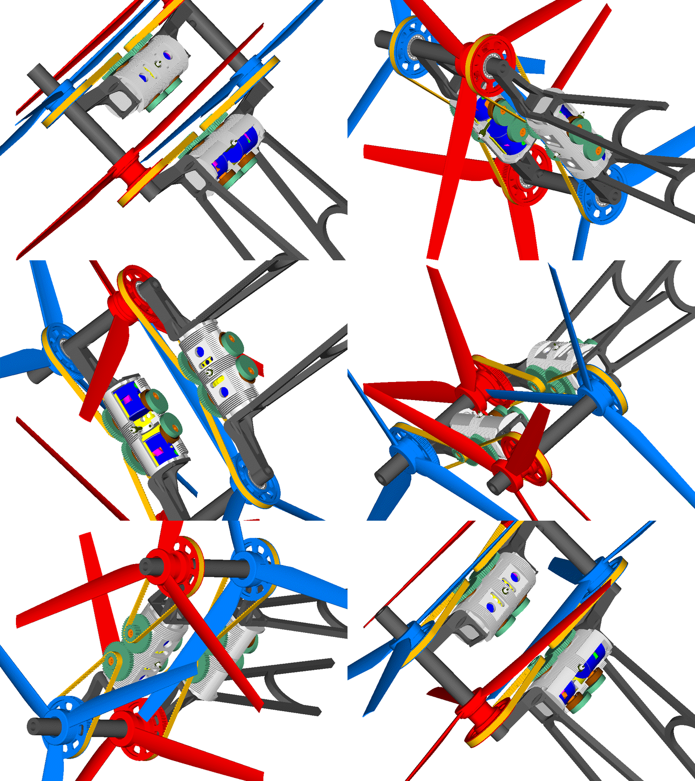
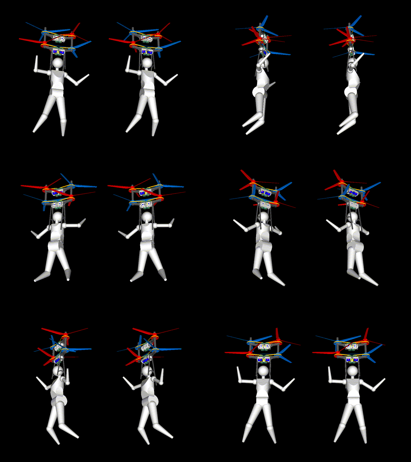
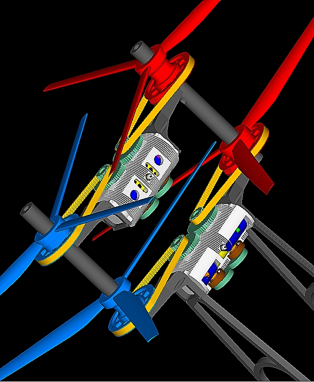
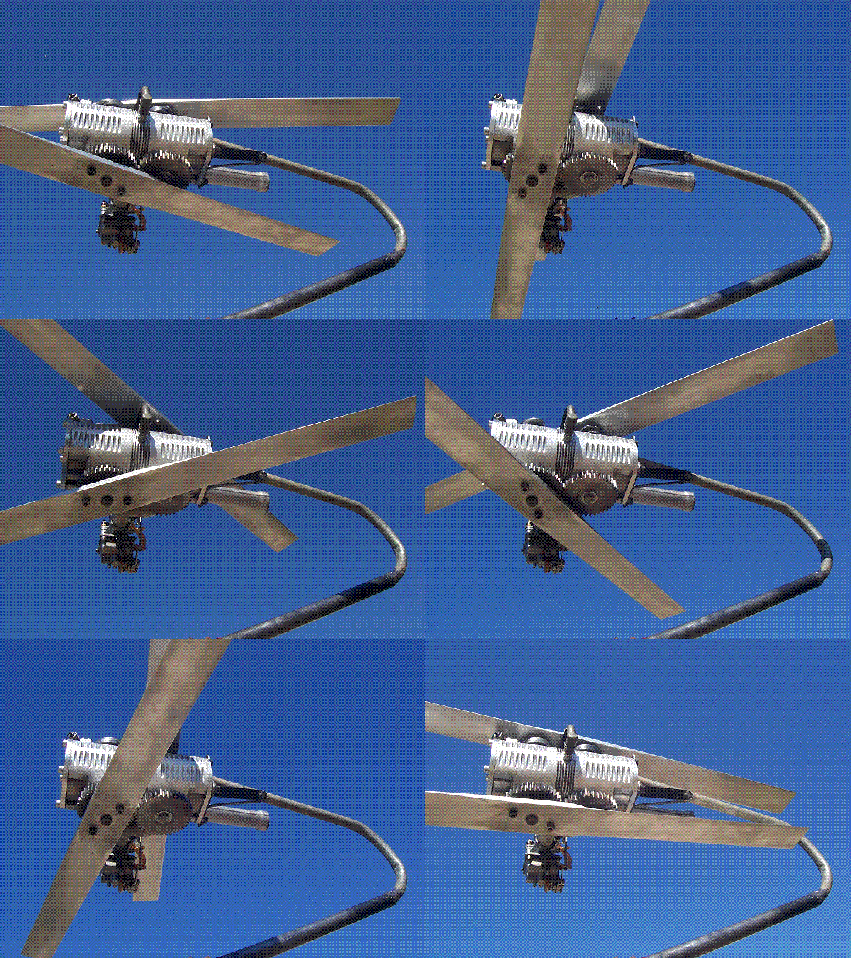
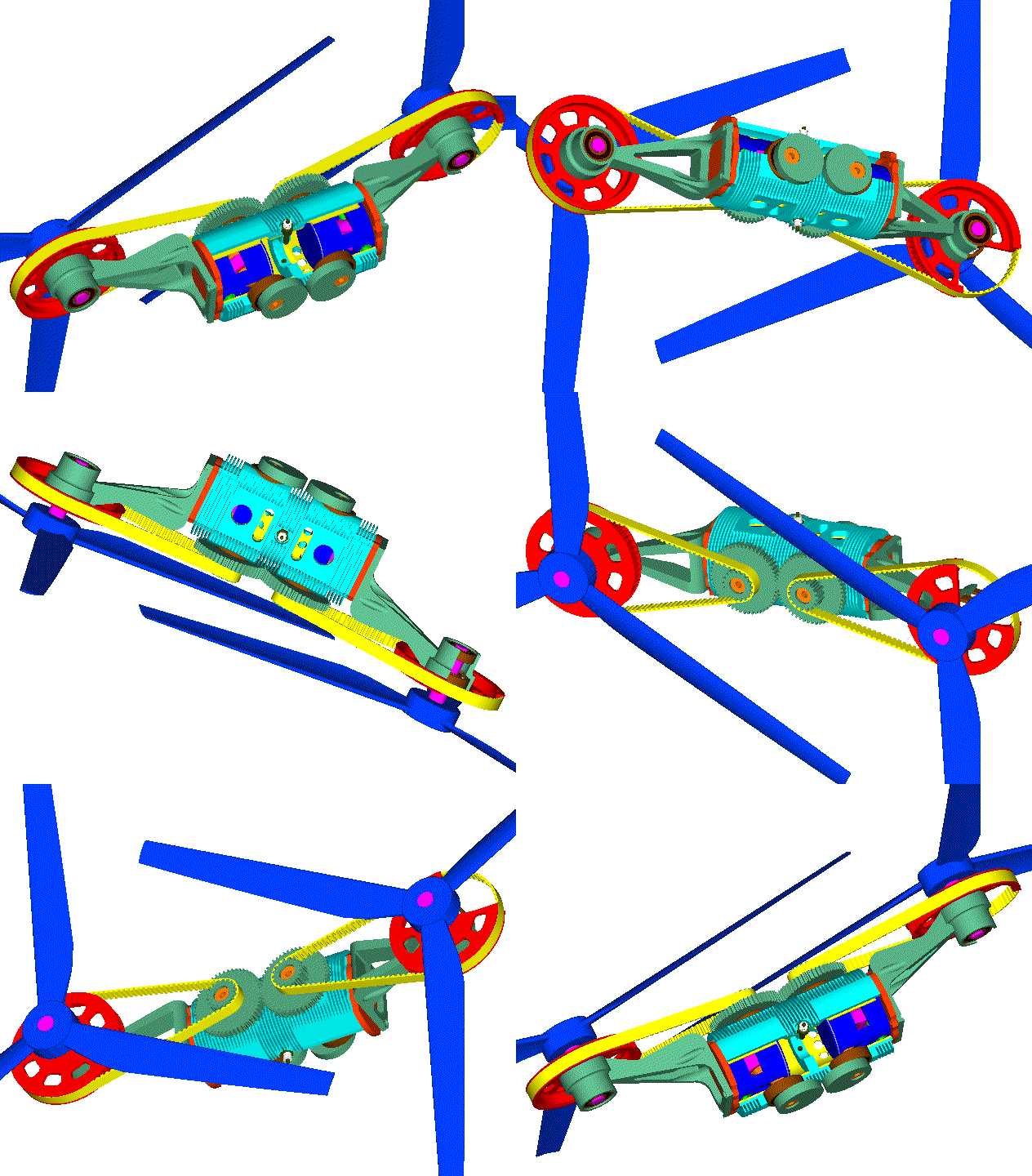
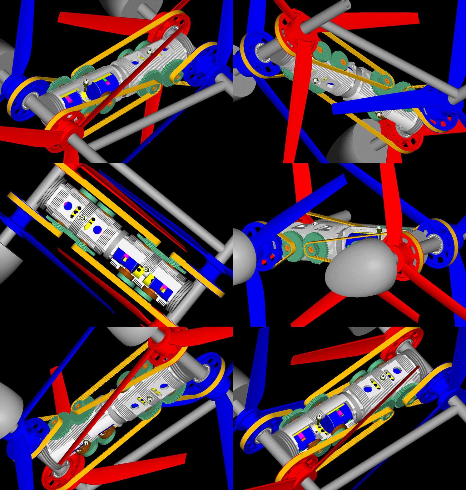
The following Portable Flyer uses two OPRE Tilting Valve engines (more at http://www.pattakon....akonTilting.htm ) each driving a pair of counter-rotating intermeshed rotors through a reduction gearing (sprockets / toothed belt).

The hubs of the rotors are hollowed.

The frame extends from bellow the lower rotors to above the top rotors, ending in cone-shaped cages improving the air flow and containing rescue parachutes for emergency landings.

PatTol_6.gif

PatTol_7.gif

PatTol_8.gif

PatTol_1.gif

PatTol_2.gif

PatTol_2_small.gif

(the last two animations are stereoscopic; help on how to look at them is at http://www.pattakon....Stereoscopy.htm )


At horizontal flight the frontal area is minimized (the engines and the pilot / rider are "in line": the one engine is hidden behind the other, the pilot is hidden behind the engines) allowing extreme maximum velocities.

The two counter rotating crankshafts of each engine "share" the same combustion chamber keeping the basis perfectly rid of inertia vibrations and of combustion vibrations.

The basis (i.e. the rider / pilot) needs not to provide any reaction torque (not even at extreme changes of revs and load).

With the symmetric counter-rotating rotors (and crankshafts), the total "gyroscopic rigidity" is zero, i.e. the rider can "instantly" (as instantly as with the rotors stopped) vector the thrust to the desirable direction.

The above make "a true neutral propulsion unit": neither vibrations, nor reaction torque, nor gyroscopic rigidity; only a force that can "instantly" and effortlessly be vectored towards the desirable direction.

As aerodynamic "controls" the rider / pilot can use his legs, hands and body, just like the wing-suiters do. A wing-suit fits with the Portable Flyer, especially for long flights and fast aerobatics.

With 1m diameter rotors and 100Kp (220lb) total (including the rider and the fuel) take-off weight, the rotor "disk loading" is only half of the rotor "disk loading" of the Osprey (Bell Boeing V22). And this is with the one only propulsion unit in action.

As the Osprey, the Portable Flyer is capable for "vertical take-off / landing (like a helicopter) and for long distance flights at high speed and low fuel consumption (like an airplane).

In the Osprey the malfunction of both engines, or the collapse of the one rotor, or the failure of the transmission may turn out fatal, especially during a vertical take-off or landing.

In comparison, the Portable Flyer of the fourth embodiment is safer, as explained in the following.

The failure of the transmission of the one propulsion unit of the Portable Flyer is not of vital importance because the other propulsion unit, alone, has its own transmission and is capable for the safe landing of the vehicle.

Even in the case wherein both engines fail, or in case the Portable Flyer runs out of fuel, the Portable Flyer can still, using the rescue parachute(s), land safely.


For more: http://www.pattakon....takonPatTol.htm

Thanks
Manolis Pattakos

#4 manolis

manolis
  • Member

  • 935 posts
  • Joined: May 03

Posted 19 March 2016 - 04:28

Hello all.

Technical Question:

With the two OPRE Tilting engines arranged the one over the other, and with each propulsion unit (comprising an OPRE Tilting engine and the two rotors it drives) being (by itself) completely neutral (its basis is perfectly rid of inertia vibrations and of combustion vibrations, its two rotors counter-rotate eliminating its total gyroscopic rigidity, etc),

which is the preferable direction of rotation of the top rotors relative to the lower rotors?

And why?


Both arrangements work.

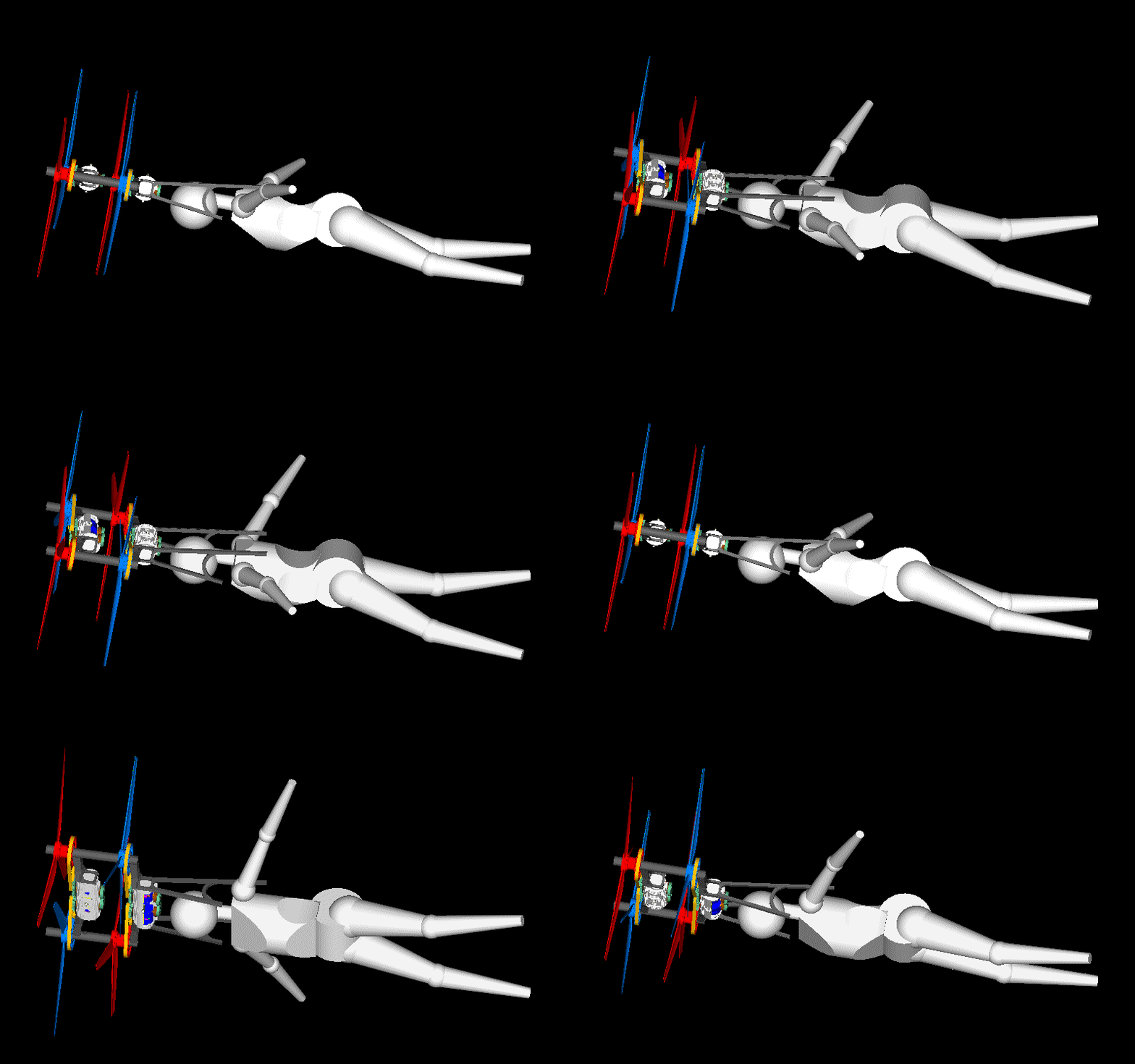
In the one arrangement (that shown in the animations), the two left rotors contra-rotate.

In the other arrangement:

PatTol_1B.jpg

the two left rotors rotate at same direction.


Is the preferable best arrangement you see, best for both: hovering and cruising?

Thanks
Manolis Pattakos
#5 gruntguru

gruntguru
  • Member

  • 7,683 posts
  • Joined: January 09

Posted 19 March 2016 - 10:42

I believe it is more aerodynamically efficient for the contra-rotating rotors to be on the same axis. Any airscrew drives the air axially but also with some rotation. The rotation does not assist thrust so is an inefficiency. Contra-rotating airscrews sharing an axis can be set up to minimise rotation whereas a pair sharing an axis and direction of rotation will obviously impart even more rotation to the air than a single screw.


#6 Greg Locock

Greg Locock
  • Member

  • 6,448 posts
  • Joined: March 03

Posted 20 March 2016 - 07:50

I suspect that contra rotating blades on parallel axes are more efficient than contra rotating blades on the same axis. Perhaps more succinctly, you only go to contra rotating blades on the same axis if you are desperate. 


#7 MatsNorway

MatsNorway
  • Member

  • 2,822 posts
  • Joined: December 09

Posted 20 March 2016 - 08:17

It is really easy for Manolis to do that tho.


Just let the belts be a little longer so they attach to the other pulley..

He only need new belts and two pulleys that are slightly more offset than the width of the belt.


Edited by MatsNorway, 20 March 2016 - 16:47.


#8 manolis

manolis
  • Member

  • 935 posts
  • Joined: May 03

Posted 20 March 2016 - 09:58

Hello Gruntguru and Greg Locock.

It seems it is not easy to predict which arrangement is better. Practice will show.


Hello MatsNorway.

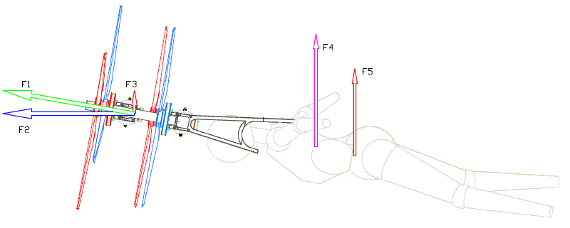
There is an easier way: all you have to do is to turn the top propulsion unit (i.e. the top OPRE Tilting engine and the two rotors it drives) for 180 degrees about the central perpendicular axis of the Portable Flyer at hovering.

Thanks
Manolis Pattakos
Edited by manolis, 20 March 2016 - 10:00.


#9 Kelpiecross

Kelpiecross
  • Member

  • 1,730 posts
  • Joined: October 10

Posted 20 March 2016 - 11:52

The older model Flyer - the single-engined variety - would have been very heavy - this one would be about twice as heavy and twice as awkward.

Maybe you could use a one-sixth scale figure (like an "Action Man" type of figure) and a couple of model plane electric motors to make a R/C test version - be very entertaining to see how it flew (and a lot safer than the full-size version)

.

#10 manolis

manolis
  • Member

  • 935 posts
  • Joined: May 03

Posted 20 March 2016 - 18:45

Hello Kelpiecross

You write:
“The older model Flyer - the single-engined variety - would have been very heavy - this one would be about twice as heavy and twice as awkward.”


Things are quite different than 1+1=2.

Here is the single-engine OPRE Tilting Portable Flyer:

OPRE_tilting_flyer.gif

wherein each crankshaft drives directly its own rotor,

With propellers of 1m diameter, you cannot go beyond, say, 5,000rpm because the tip speed gets too high and the propellers get, aerodynamically, too inefficient.


In this version:

OPRE_Tilting_Reduction_Toothed_Belts.gif

the reduction gearing bridges the gap between the high revving capacity of the OPRE Tilting engine and the optimum speed of the propellers it drives.

The OPRE Tilting prototype has a piston stroke of 30mm (i.e. 60mm combined stroke) for an 84mm bore (333cc capacity).

At 5,000rpm this engine has only 5m/sec mean piston speed.

At the “extreme” 10,000rpm, the mean piston speed is still too low: 10m/sec.

A two-stroke 333cc gasoline engine running at 10,000rpm produces easily some 70PS keeping its reliability high (in comparison, at half engine revs (i.e. at 5,000rpm), the same engine provides only the half power (i.e. some 35PS); this makes clear the limitations introduced by the direct driving of the propellers by the crankshafts of an engine capable for high revving (previous case)).

So, with the reduction gearing, you can operate the engine at 10,000rpm and the rotors / propellers at only, say, 4,000rpm.

But if something gets wrong with the engine, or with the propellers, or with the transmission (belt, sprockets), the problem may turn fatal.


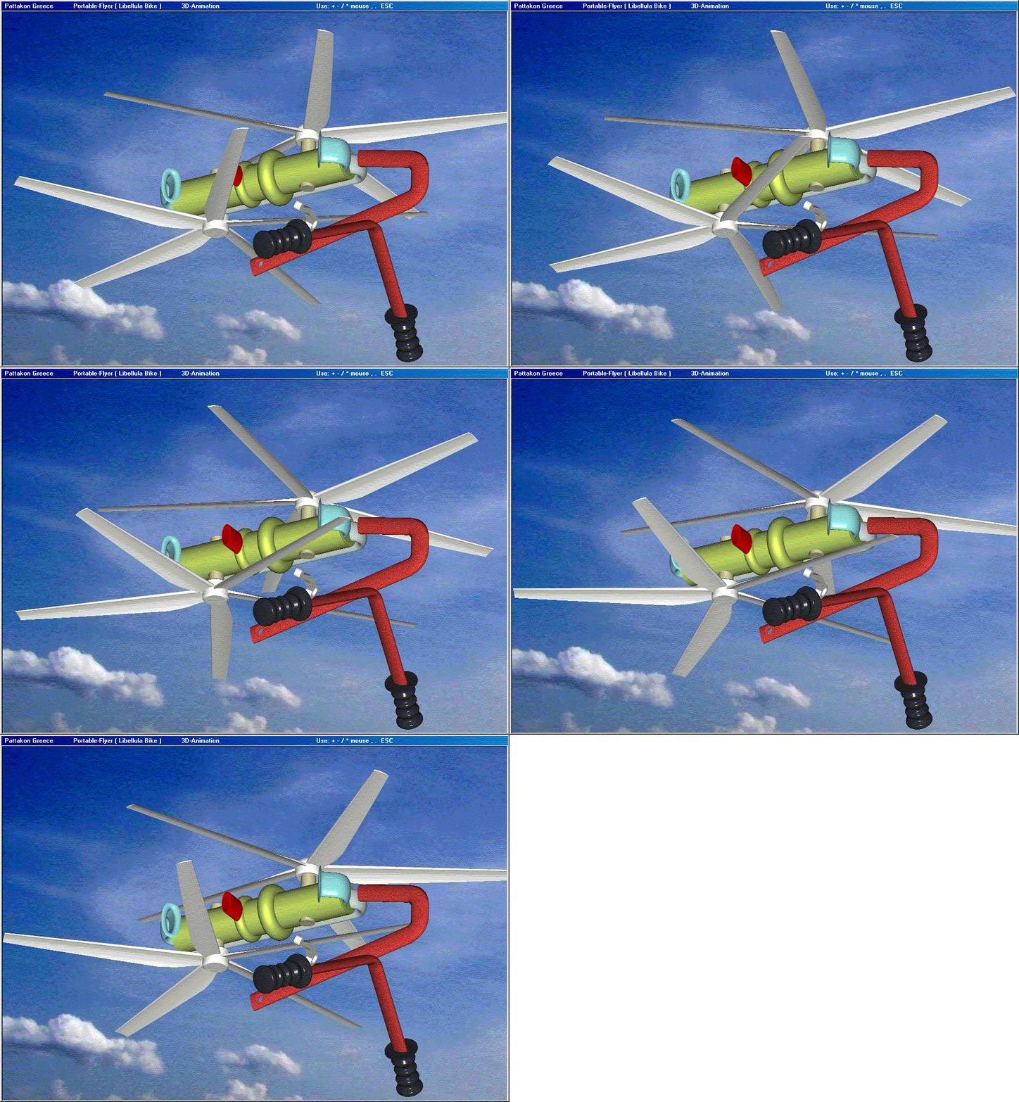
Instead of having a single OPRE Tilting engine of 333cc capacity, you can have a pair of smaller OPRE Tilting engines, each of, say, 200cc capacity (combined stroke 49mm, bore 72mm), like:

PatTol_1B.jpg

If you run them at the same mean piston speed of 10m/sec (i.e. at 12,000rpm), each can provide some 50PS (i.e. 100PS in total).

The total weight of the two small OPRE Tilting engines is similar with the weight of the single bigger OPRE Tilting engine.

The available total power is by some 50% increased.

And if something gets wrong with the one “propulsion unit”, you have the other for a safe landing.

So, the target for the overall weight of the “dry” Portable Flyer remains quite low (bellow 20Kp (44lb)) either with one or with two propulsion units.

If you go above 25Kp (55lb) total “dry” weight, things get tough during landing.

If you go above 35Kp (77lb) total “dry” weight, things start being dangerous for a normal size pilot/rider.

You could secure a weight like the abovementioned on your shoulders and try jumping to the floor from a table 1m high, to understand what I mean.
But do not try, because you may hurt your legs / knees.


You also write:
“Maybe you could use a one-sixth scale figure (like an "Action Man" type of figure) and a couple of model plane electric motors to make a R/C test version - be very entertaining to see how it flew (and a lot safer than the full-size version)”

The problem with an unmanned RC is that you have not a living / sensing / responding fuselage (the body of the pilot / rider), so you cannot really evaluate the characteristics of this vehicle in real action.


Look at the Portable Flyer from a different viewpoint:

In the Portable Flyer the center is the pilot / rider.
The pilot / rider comprises some 75% of the total weight of the vehicle.
The body of the pilot / rider is: the vehicle and the sensors and the control unit and the servomechanisms and the landing system, just like the bodies of the birds, bats and bugs.
The engines are there to provide the power the human body is unable to provide.


Thanks
Manolis Pattakos
Edited by manolis, 20 March 2016 - 18:55.


#11 manolis

manolis
  • Member

  • 935 posts
  • Joined: May 03

Posted 22 March 2016 - 10:27

Hello all.

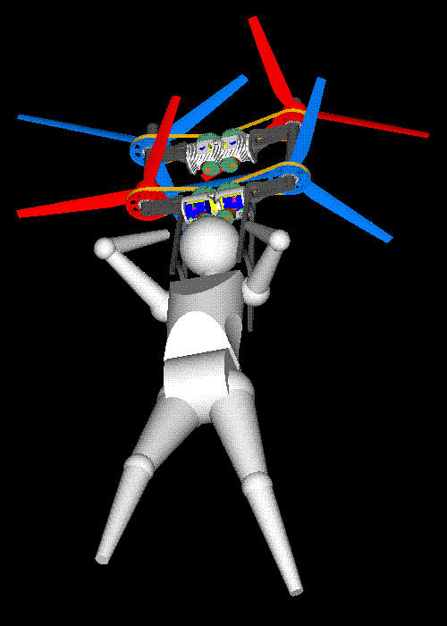
Here are an animation:

Portable_Flyer_Direction.gif

and a drawing:

Portable_Flyer_Forces.gif

showing the direction of the Portable Flyer and of the body (and wingsuit, not shown) of the pilot / rider at horizontal flight.

They are made to show that the Portable Flyer is not “seriously nose heavy”.

Thanks
Manolis Pattakos
#12 gruntguru

gruntguru
  • Member

  • 7,683 posts
  • Joined: January 09

Posted 22 March 2016 - 23:32

1. The CG of the combined pilot and thrust unit will be significantly further forward than the pilot alone. This would require a wing suit with the centre of lift similarly displaced from the usual.


2. The mass of the thrust unit will be exerting a significant moment on the shoulder connection. I have seen your mock-up in an earlier post. Try lying face-down on a table or bench with the thrust unit unsupported. See if you can control the elevation of the thruster with your shoulders.


#13 manolis

manolis
  • Member

  • 935 posts
  • Joined: May 03

Posted 23 March 2016 - 08:18

Hello Gruntguru.

You write:
“The CG of the combined pilot and thrust unit will be significantly further forward than the pilot alone. This would require a wing suit with the centre of lift similarly displaced from the usual.”

With the fuel tanks (a pair of plastic bottles) secured on the legs, just above the ankles (or under the ankles) of the pilot / rider, the center of gravity is, during the take-off, not significantly lifted.

What about when the fuel tanks are almost empty?

At horizontal flight like an airplane, the engines / rotors provide the requited thrust. The rotor axes are not horizontal. They “look” slightly upwards providing a part of the required lift. The rest lift is provided by the wingsuit and the body of the pilot / rider (see the drawing with the forces in my previous post)
If for some reason the nose starts lowering, the propulsion unit is vectored a little upwards and the horizontal flight continues.


You also write:
“The mass of the thrust unit will be exerting a significant moment on the shoulder connection. I have seen your mock-up in an earlier post. Try lying face-down on a table or bench with the thrust unit unsupported. See if you can control the elevation of the thruster with your shoulders.”

During take-off the pilot / rider stands straight up (upright), which means that no significant moment is required by body to keep the thrust unit from falling.

During horizontal (or nearly horizontal) flight, the thrust unit lifts both: itself and the pilot / rider, and is not lifted by the pilot / rider.

I can’t see the problem.


Regarding the HandleBars:

The initial designs of the Portable Flyer have HandleBars:

Flyer_HandleBars.gif

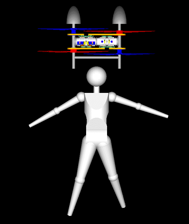
Even with the new designs, the pilot rider can hold, by his hands, the frame of the Portable Flyer, like:

Flyer_HandleBars2.gif

to control more accurately and more rapidly the displacement of the propulsion unit relative to the body of the pilot.

Thanks
Manolis Pattakos
#14 gruntguru

gruntguru
  • Member

  • 7,683 posts
  • Joined: January 09

Posted 23 March 2016 - 22:19


At horizontal flight like an airplane, the engines / rotors provide the requited thrust. The rotor axes are not horizontal. They “look” slightly upwards providing a part of the required lift. The rest lift is provided by the wingsuit and the body of the pilot / rider (see the drawing with the forces in my previous post)
If for some reason the nose starts lowering, the propulsion unit is vectored a little upwards and the horizontal flight continues.

Sounds dangerous to me. If the motor cuts out in horizontal flight the flyer goes into a dive.


#15 manolis

manolis
  • Member

  • 935 posts
  • Joined: May 03

Posted 24 March 2016 - 07:34

Hello Gruntguru.

You write:
“Sounds dangerous to me. If the motor cuts out in horizontal flight the flyer goes into a dive.”

If both motors cut out in horizontal flight, the Portable Flyer dives accelerating, then the pilot / rider can use his body / wingsuit to change direction, even to make loops.

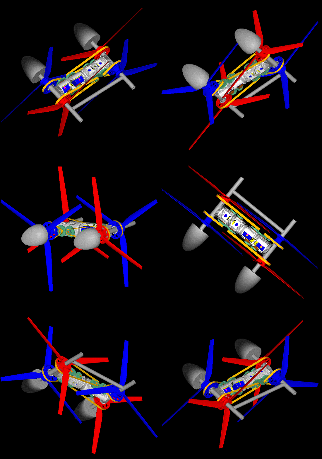
Even in this case wherein both engines cut off, there are rescue parachutes inside the spinners.

PatTol_axial_pilot.gif

PatTol_axial1.gif

PatTol_axial2.gif

Thanks
Manolis Pattakos
#16 gruntguru

gruntguru
  • Member

  • 7,683 posts
  • Joined: January 09

Posted 24 March 2016 - 08:32

Hello Gruntguru.

You write:
“Sounds dangerous to me. If the motor cuts out in horizontal flight the flyer goes into a dive.”

If both motors cut out in horizontal flight, the Portable Flyer dives accelerating, then the pilot / rider can use his body / wingsuit to change direction, even to make loops.


1. No joy in an "accelerating dive" if you are flying at low level.

2. A nose-heavy glider cannot be "pulled up" let alone make loops. Build yourself a "chuck-glider". Add appropriate ballast at the nose and see what happens when you trim the tailplane to seek level flight.


It is ESSENTIAL that you balance your machine such that it will glide with power off. It is easy to do. The wing suit must be designed with the centre of lift near the centre of gravity.


#17 manolis

manolis
  • Member

  • 935 posts
  • Joined: May 03

Posted 28 March 2016 - 08:28

Hello Gruntguru.

You write:

“1. No joy in an "accelerating dive" if you are flying at low level.
2. A nose-heavy glider cannot be "pulled up" let alone make loops. Build yourself a "chuck-glider". Add appropriate ballast at the nose and see what happens when you trim the tailplane to seek level flight.
It is ESSENTIAL that you balance your machine such that it will glide with power off. It is easy to do. The wing suit must be designed with the centre of lift near the centre of gravity.”

Here is a modified paper toy (paper-glider-toy) wherein a paper rod secured (by two pins) at the nose of a conventional paper-glider-toy displaces the Center of Gravity (the point next to the label “CG” on the paper rod) ahead all surfaces providing aerodynamic lift:

paper_glider_toy_1.jpg

paper_glider_toy_2.jpg

The back ends of the wings are bent upwards (in the case of the pilot / rider of the Portable Flyer it is like the pilot / rider keeps his legs, under the knees, bent).

If you throw the paper-toy-glider horizontally at a speed, it keeps its horizontal orientation until it lands on the ground.

If the paper-glider-toy is left from a height with the nose down, initially falls gathering speed and then it turns horizontal and continues horizontal. In the Portable Flyer case, the pilot / rider accelerates “nose down” (case with engine power off) with the minimum frontal area (he keeps retracted his hands and legs), and when the speed is adequately high (say 320Km/h / 200mph)) he changes his “shape” (extracting / displacing / bending his hands / legs) to make loops or aerobatic.

It appears that even without power from the engines, the pilot / rider of the Portable Flyer has full control.

The Portable Flyer seems competent for high speed flights at good mileage and for aerobatics similar to those of Rossy's.

In case of loss of power near the ground, the pilot has the rescue parachutes.


The full control over the flight at all conditions is a necessity.

Important is also the safety provided by the two fully-independent propulsion units, each capable for a safe landing.
Compare with the case the unique engine of the Martin JetPack (priced at some 150,000 US dollars) cuts-off / stalls at 25m above the ground.

Or, compare to the case the one rotor of the Osprey V-22 is destroyed when it hovers 40m above the ground.


The simplicity is another characteristic of the Portable Flyer. No servomechanisms, no fly-by-wire, no landing gearing, not even a seat. The sensing and control mechanisms is the body / brain of the pilot / rider.

The simplicity along with improving reliability, minimizes the cost.
Why 150,000 or 200,000 US dollars for the Martin JetPack, or for a PAL-V, or the Ehang-184?


The cost of a Portable Flyer (there are neither wheels, nor brakes, nor suspension, nor seat etc) should be less than a decent motorcycle.


By the way, does anybody know if the rotary valves are allowed in the Moto-GP?
Or they are forbidden as in Formula1?

Thanks
Manolis Pattakos
Edited by manolis, 28 March 2016 - 09:02.