You write:
“The brochure is for a genset not a range extender. Some advantages are:
No oil
No coolant
1000 hr service interval
Low volume
Low weight”
My wrong.
However, the gen-set specifications are the only specifications they provide.
Judging from these specifications (12kW Power Output, 26.5% efficiency, 580Kp) things sound not promising for their REM which should be some 10 times more lightweight (say 60Kp at most), some 2 times more powerful (say 25kW) and substantially more efficient (the 26.5% is just low).
May I suppose that If they could built such a REM, they would sell it as a gen-set, too?
Quote from the PDF in the first post:
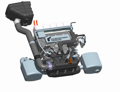
3. KSPG ñ FEV V2 Range Extender
In September 2011, Kolbenschmidt Pierburg (now KSPG) together with FEV presented the concept of compact on-board auxiliary power unit for electric vehicle basing on the V-2 90° spark ignition engine with a vertical crankshaft [10]. A general view of the device model is presented in Fig. 3.
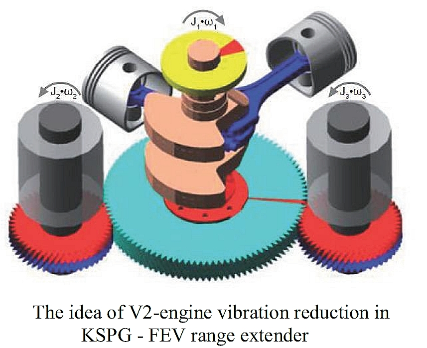
Two synchronous electric generators with permanent magnets (PMSM) with four pairs of poles connected in series are driven from the engine through a gear train. The use of two generators driven by gears from the engine allows for a significant reduction of irregularity of running of V-twin cylinder engine. The idea of using of generator rotors as V-twin engine flywheels is shown in Fig 4
The innovative vibration reduction system presented in the figure above is called FEVcom.
Beyond the fuel tank and the radiator all of the components are mounted on the support frame. The use of the engine with vertical shaft allows for a very small total height of the range extender. The result is that it can be easily mounted instead the spare wheel even in relatively small car. Such positioning of the team is also optimal in terms of NVH. Noise and vibration during start and operation will be significantly reduced. The project also includes easy assembly and disassembly of the unit. Basic Specifications KSPG - FEV Range-Extender is presented in Table 1
Nominal power of the device has been determined based on a calculation of the average power demand of segment A car traveling at 100 km/h the hill with a slope of 3%.
The engine has two valves per cylinder, fuel injection into the intake pipe and meets the emission standard Euro 6. The cooling system is common for an internal combustion engine, generator and inverter.
End of quote.
FEV – KSPG have performed the “coin test” with their REM.
With their arrangement (the flywheel of the engine drives a pair of electric generators) the free inertia torque can be reduced or eliminated.
But what about the combustion torque pulses?
During a compression – combustion – expansion in a combustion chamber, the casing of the engine has to provide a strong reaction torque.
The same is true for the Wankel Rotary REM’s: during each combustion, the casing has to provide a reaction torque pulse.
Only the turbine REM is really good in this field.
And why the elimination of the vibrations is significant in a REM for electric cars?
Because every time the REM operates charging the batteries, the conditions in the cabin change noticeably: vibrations, noise.
Suppose we need a REM (or a gen-set, or a propulsion unit) wherein the basis is perfectly rid of vibrations (think of a REM for a Robot, for instance, or of a REM for a super car).
The AVL REM (Fig 6 in the PDF of the first post of this thread) comprises a Wankel Rotary engine and an electric generator driven directly by the Wankel Rotary engine power shaft (similarly for the FEV REM with the Wankel Rotary engine, that shown in Fig 1 of the same PDF file).
The rotor of the electric generator together with the power shaft and the rotor of the Wankel Rotary engine is the flywheel of the system.
Every compression – combustion – expansion creates a strong torque pulse on the basis of the REM; the heavier the load, the stronger the combustion torque pulse that loads and vibrates the basis of the REM and the vehicle whereon the REM is secured / supported.
Is there a way to avoid these power pulses and vibrations of the Wankel REMs?
There is: the power shaft of the Wankel drives the electric generator indirectly at the reverse direction (say by a pair of gearwheels) AND the moment of inertia of the rotor of the electric generator times the transmission ratio equals to the “moment of inertia” of the assembly comprising the power shaft and the rotor of the rotary engine (the rotor of the Wankel engine performs two motions, a slow (1/3) rotation about the eccentric pin whereon it is rotatably mounted and a rotation together with the power shaft).
A drawback: the need for a transmission (cost, friction loss, reliability etc).
A problem / difficulty: the moment of inertia of the abovementioned assembly (power shaft and rotor) of the Wankel Rotary engine is, in most cases, substantially smaller than the moment of inertia of the rotor of the electric generator (see Fig 1, FEV REM in the PDF file), which means the electric generator angular speed should be substantially lower, which is not good for the power concentration (power to weight ratio) of the REM.
The perfect torque balance is attainable because the Wankel Rotary has a special characteristic: for constant angular velocity of its power shaft, the total kinetic energy of its moving parts (power shaft and rotor) remains constant. As mentioned before, the drawbacks is the need of a transmission (friction / cost) and the need to align / to “balance” the moment of inertia of the two subsystems (which means a compromise on the speed of the electric generator which, typically, can run efficiently at higher revs than the internal combustion engine).
On a similar principle is based the FEV / KSPG REM (Fig 4 of the abovementioned PDF).
The two electric generators spin at the same direction, which is opposite to the direction the flywheel of the V2 engine rotates.
The rotation at a constant speed of the crankshaft causes the reciprocation of the pistons and the rotation of the electric generators.
The total kinetic energy of the moving parts varies during a crankshaft rotation (not as much as in a conventional in-line four, but it does vary) generating a free inertia torque and requiring an opposite reaction torque by the basis of the engine.
Excluding the two electric generators, the actual moment of inertia of the rest moving parts varies during a rotation of the crankshaft; it is like having a flywheel of variable radius or of variable mass.
The resulting torque on the basis of the REM cannot be eliminated. It reduces substantially, but it cannot be eliminated (as happens in the previously described Wankel REM that drives indirectly the electric generator).
This drawing helps:
It shows a twin boxer engine having simultaneous combustion in both cylinders (typical arrangement for aero 2-stroke and RC 2-stroke engines, easy to be applied to 4-stroke twin boxers to turn them to “big-bang”) and driving by its crankshaft a counter-rotating electric generator (the FEV – KSPG REM uses a V2 which has a substantially lower free inertia torque, however the following theory is applicable to the FEV – KSPG REM, too).
With expansion at both cylinders simultaneously (for simplicity), they are generated the two opposite and equal forces F1 and F2 on the casing of the engine, they are also generated (due to the leaning of the connecting rods) the thrust forces F3 and F4: a pair of forces (i.e. a torque) that tries to rotate the casing counter-clockwise.
The forces F5 and F6 acting on the crankshaft try to accelerate the crankshaft clockwise.
The blue flywheel (say, the rotor of the electric generator) is driven – through a pair of synchronizing gearwheels – by the crankshaft and rotates counter-clockwise.
The crankshaft applies a force F8 on the top of the periphery of the blue flywheel, which loads the casing at the bearing of the blue flywheel with a force F10.
The reaction force F7 (the F7 is equal with, and opposite to, the F8) acting on the crankshaft loads the casing (at the main bearings of the crankshaft) with a force F9.
The pair of forces F9 - F10 tries to rotate the casing clockwise and cancels the action of the pair of forces F3 – F4 (the forces acting on the casing are marked by red color).
If the moment of inertia of the blue flywheel were equal to the “actual” moment of inertia of the assembly comprising the pistons, the connecting rods and the crankshaft, then the casing would be perfectly rid of “combustion torque” vibrations.
However, the “actual” (or apparent, or instant) moment of inertia of the assembly of the crankshaft / connecting rods / pistons varies during a rotation of the crankshaft, while the moment of inertia of the blue flywheel remains constant.
This means that during a complete crankshaft rotation the combustion torque F3 – F4 is perfectly counterbalanced by the F9 – F10 torque at some angles, at some other angles the F3 – F4 is bigger than the F9 – F10 torque, and at some other angles of the crankshaft the F3 – F4 is smaller than the F9 – F10.
How much “bigger” and “smaller”? It depends on the free inertia torque of the arrangement; for instance, with two heavy pistons, the free inertia torque increases.
A V2 with 90-degrees Vee is substantially better than a boxer (or than an even firing twin or than a conventional in-line-four which is one of the worst choices because of its big free inertia torque).
A V-8 is much better.
A V-12 is perfect.
But as in the case of the Wankel REM with the counter-rotating electric generator, the drawbacks in the case with the reciprocating engines are significant too: a transmission (friction, cost, complication etc) is required, the electric generator, which has a significant moment of inertia, has to run at lower than it optimum revs, etc.
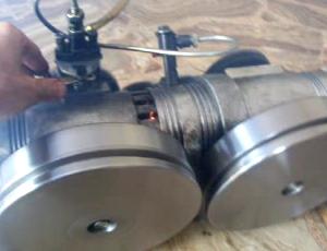
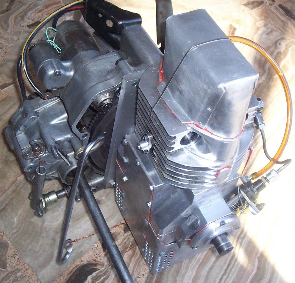
In comparison to the previous, think the case wherein a Opposed Piston PatMar (a two-stroke port-less through-scavenged crosshead engine having true four-stroke lubrication, true four-stroke specific lube consumption and true four-stroke scuffing resistance; more about the PatMar: http://www.pattakon....takonPatMar.htm ) drives directly two counter-rotating electric generators, one with each crankshaft.
The Opposed Piston PatMar REM (the electric generators are not shown) at BDC:
The Opposed Piston PatMar REM at TDC:
The timing is as asymmetric as desirable (for instance, the exhaust opens first and closes first).
The two crankshafts have zero phase difference and share the same combustion chamber (which means, the synchronizing gearing runs unloaded, which means that a PatBelt (more at http://www.pattakon....akonPatBelt.htm ) is OK.
Without compromises (as those mentioned in the previous analysis) the basis of the Opposed Piston PatMar REM (or gen-set) is perfectly rid of inertia and of combustion vibrations.
The total kinetic energy of the moving parts varies during a crankshaft rotation (not as much as in a conventional in-line four, but it does vary) generating a free inertia torque and requiring an opposite reaction torque by the basis of the engine.
Excluding the two electric generators, the actual moment of inertia of the rest moving parts varies during a rotation of the crankshaft; it is like having a flywheel of variable radius or of variable mass.
No. The total kinetic energy of the moving parts does not vary during a crankshaft rotation. What varies is the proportion of rotational and linear kinetic energy.
Likewise, the apparently "variable flywheel" does not have a variable rotational inertia. It is the parts in linear motion that vary in velocity and apply a variable torque to the flywheel. This does not apply a torque to the casing.
Simplify your diagram by replacing the connecting rods with scotch yoke mechanisms which apply zero side thrust to the pistons. The inertia situation is the same but F3 and F4 disappear (because they are not inertial forces they are mechanism forces opposing the vertical component of F5 and F6).
Micro-turbines seem natural for range extender modules, except that they tend to have poor efficiency.
It seems logical that if waste heat from the exhaust could be used to heat the combustion air between the compressor and the combustion chamber, efficiency would be improved.
But from what I can see, efficiencies are still low, around 30%.
A microturbine with recuperator:
Even so, they have been adopted for some serial hybrid vehicles.
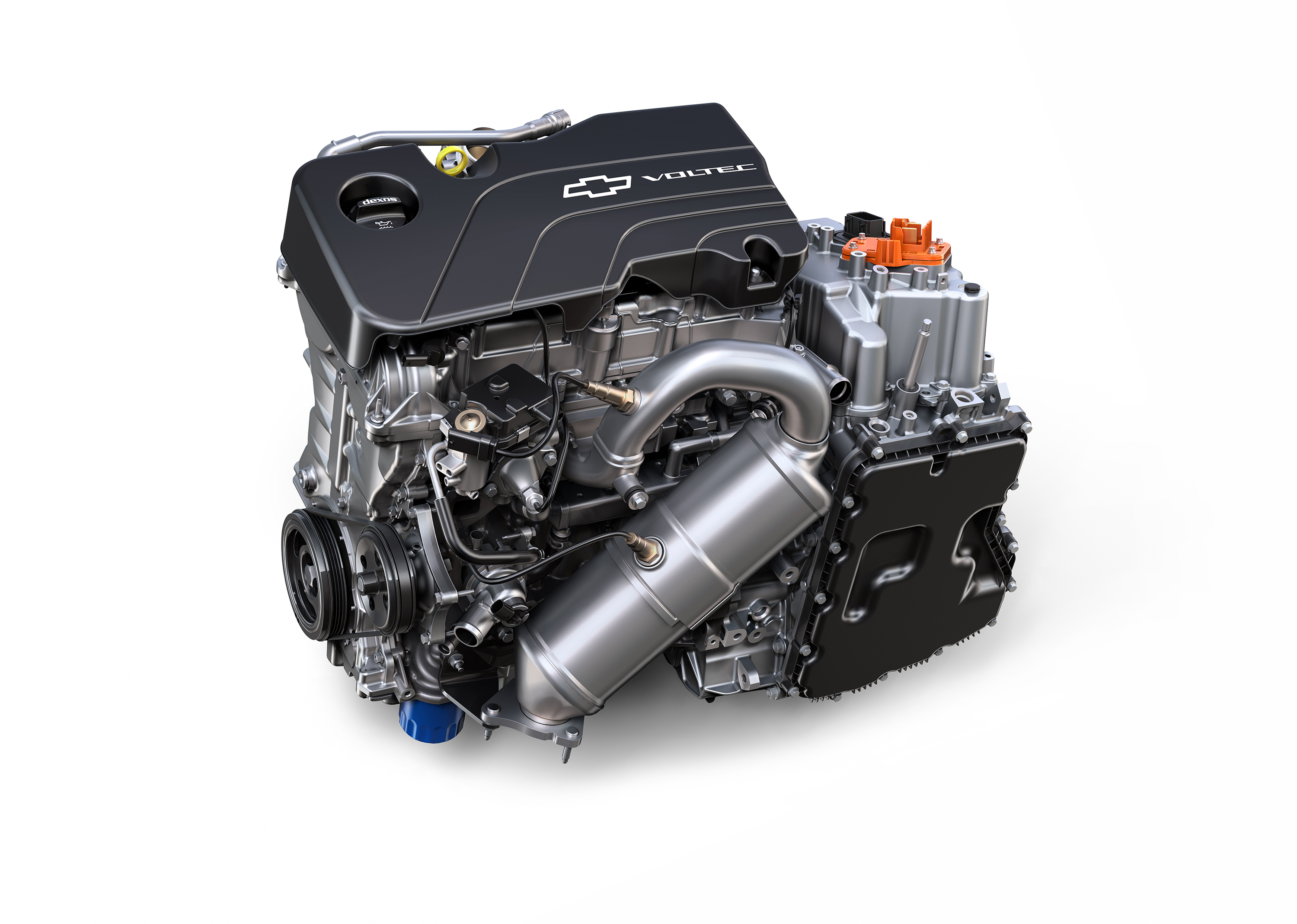
BMW sell an EV with an optional range extender. Yes, it is basically like carrying a large generator around with your EV. The Chevrolet Volt is the same idea, except they went for a small battery and a big engine. There was one rather obscure mode/regime where the engine drives the wheels mechanically, but most of the time it behaves like an EV or a series hybrid.
Revolutionary engine maker Liquid Piston seeks commercialization partners after landing $2.5 million DARPA funding for 40HP engine that will be 30 lbs instead of conventional 2700 lbs for diesel
End of quote.
Without special care on the weight reduction, this direct-injection Diesel engine: