
Ladies and gents,
Some time ago, I posted some info regarding a set of Howarth low pressure fuel injection that I had purchased. The Howarth setup was installed on a set of Repco HighPower cross-flow head manifolds. I did some reverse engineering on the Howarth set-up here:
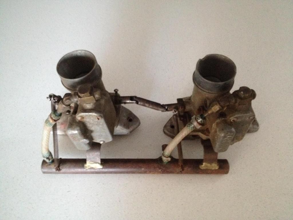
As part of the same purchase, I obtained a set of two sidedraught carburettors, which I will discuss in the thread below.
http://i929.photobuc...zps3mqf8m5u.jpg
Like the injection set, the sidedraughts were mounted on (yet another) set of Repco HighPower cross-flow head manifolds. I had originally made a deal to purchase a HighPower head, though sadly the seller pulled out of the deal (great… now I’ve got two sets of fuel setup and no cylinder head to put them on  ).
).
The history on both my Howarth injection and these sidedraught carburettors has been lost. The seller understood that both injection and carburettors were used on Repco heads (Holden grey motors), one in a custom road circuit racer, and one in a dragster. The previous owner had the Repco heads stored in a building which burnt down, leaving only the injection/carburettors which had been stored separately. I have been able to tie-down the Howarth injection, but the carburettors are a mystery. There are no manufacturers markings, stamps or castings on the carburettors. As we will see below, the carburettors seem to take parts from a number of sources. I checked with Carburettor Service Company in Sydney, and they were of the view that the carburettors were custom cast. Having said that, the castings are very neat, with no obvious occlusions, flash or voids. The main body casting has a yellow dichromate finish. If these are home-cast, they were a very professional job. I’ve checked a number of other period sidedraught carburettors include the Carter YH and Zenith 11ADX12 (and more mentioned in the text below), though again they are very different from these carburettors. If anyone knows the manufacturer of my carburettors, I’d love to hear from you.
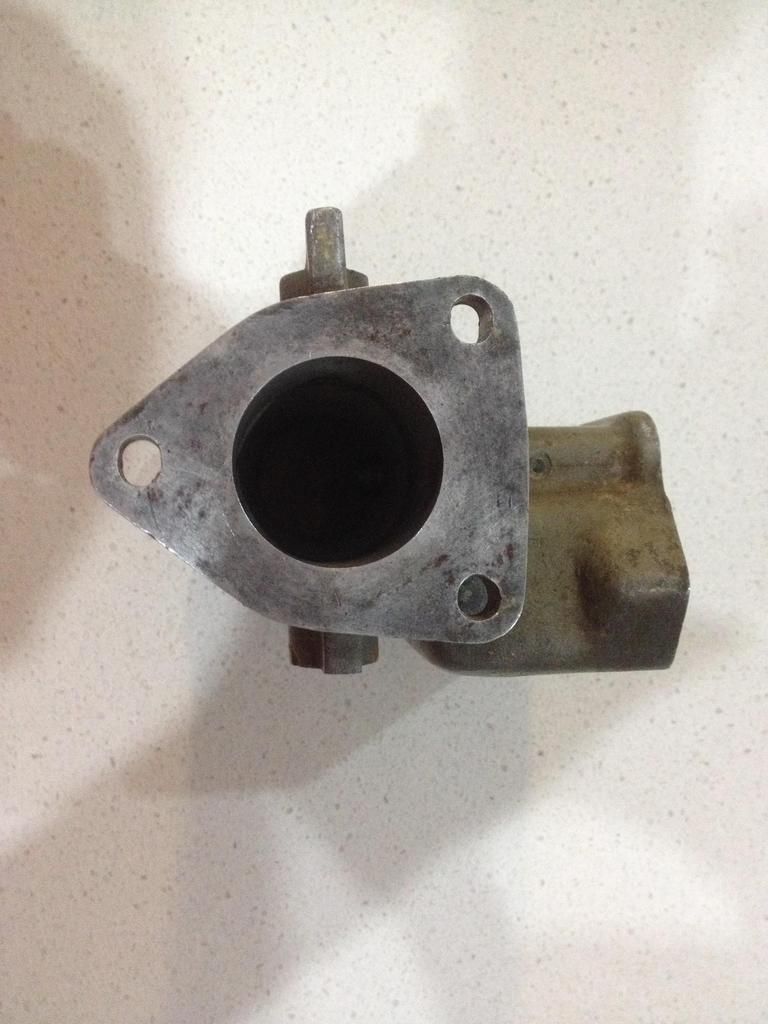
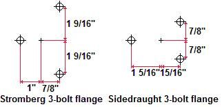
The mounting flange is a 3-bolt single barrel non-equidistant setup. It is similar to the 2-barrel Stromberg 3-bolt EE-model (“Stromberg 97”) flange, but not the same.
http://i929.photobuc...zpsdv4vlnya.jpg
http://i929.photobuc...zpszzulyyod.jpg
Some Harleys ran 3-bolt non-equidistant flanges (for example on the Linkert carbs), though these carbs look nothing like any Harley I’ve been able to Google. The steel manifold studs are ¼-20/28 UNC/UNFx15/32”. Two of the three studs on each carb have been cast into the Repco manifolds, though it looks like this was done afterwards (drill an oversize hole, insert the stud, then pour in liquid aluminium) as the studs are not altogether horizontal, and the casting is porous around the studs.
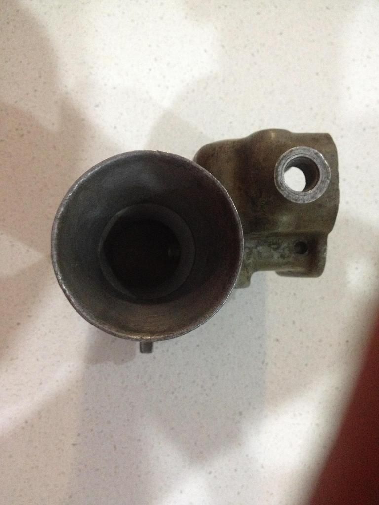
The carburettors have a throttle bore of 1 7/16”, an air horn OD of 2¼” and a venturi diameter of 11/16”. The venturis are changeable, being constructed of an interference fit aluminium sleeve, partially pinned in place by the main discharge jet mitred tip.
http://i929.photobuc...zpsgj5j5tgy.jpg
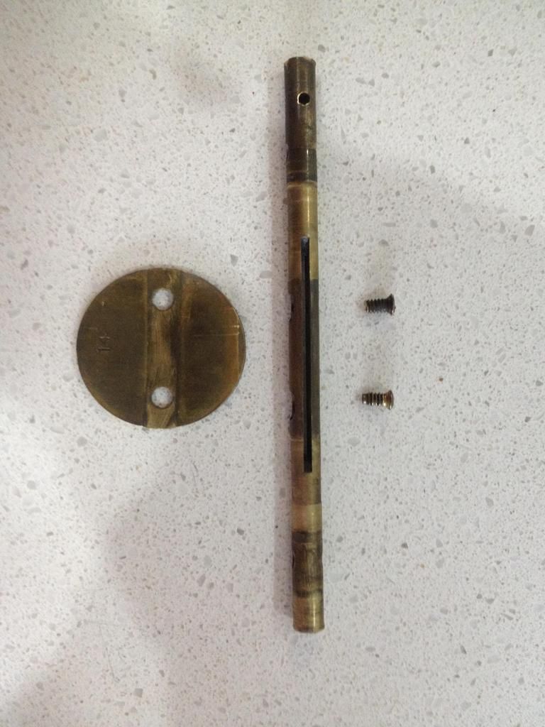
The throttle plate and shaft are both brass, held together by brass 6-32UNCx¼” raised countersink head screws. The screws are hollow point to allow them to be staked in place.
http://i929.photobuc...zpse3fjldu7.jpg
The throttle shafts are fitted with brass collars on one side, and brass idle speed levers on the other.
http://i929.photobuc...zpsmlo6ysrg.jpg
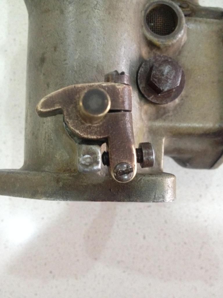
The idle speed levers are held in place with 10-32UNFx9/16” fillister head bolts, relying on the bolts to purchase onto the round throttle shaft. The idle speed levers act on a lug on the throttle body castings, and are adjusted with 10-32UNFx7/16” fillister head bolts, locked in place with a #6-32UNCx9/32” cross-screw.
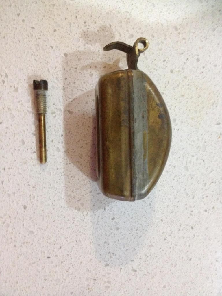
The carburettors have a single float bowl, with the liquid level controlled by a Stromberg EE-type float and screwed hinge pin.
http://i929.photobuc...zpsjlh5tsu4.jpg
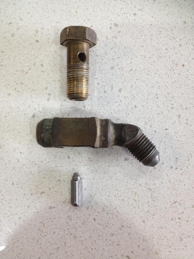
The hinge pin drilling has been made all the way through both sides of the casting. One side of the drilling is threaded (to accept the hinge pin threads) whilst the other side has been blinded off by a lead plug. Whilst the floats are Stromberg, Stromberg however only made one type of sidedraught carburettor (the OH model), and this looks nothing like it (the OH for example had a round-shaped float). The needle and seat orifice, located inside the inlet banjo fittings, is 0.104”. This is considerably larger than a standard grey motor (0.070”), and closer to typical Holley (0.110”). The larger diameter needle and seat orifice would support methanol flow. The outlet of the banjo fittings is sized to -4AN, whilst the inlets are the funky 7/16”-24 thread used in Stromberg carburettor fuel inlet threads.
http://i929.photobuc...zpsjsjkbhxk.jpg
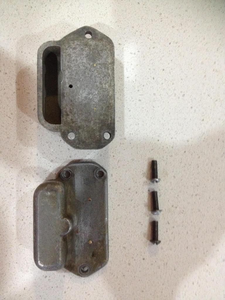
The float bowl is 1 11/16” deep, and contains an integral-cast metering block. The drawings below show the float bowl in cross-section, with the float bowl lid shown in pink. The float bowl lid, fastened by three 10-32UNFx9/16” round-head bolts, has a single hole drilled through the casting to vent the float bowl. The hole is drilled at 0.070” diameter vertically, and then at 0.078” horizontally.
http://i929.photobuc...zpsw748v2ns.jpg
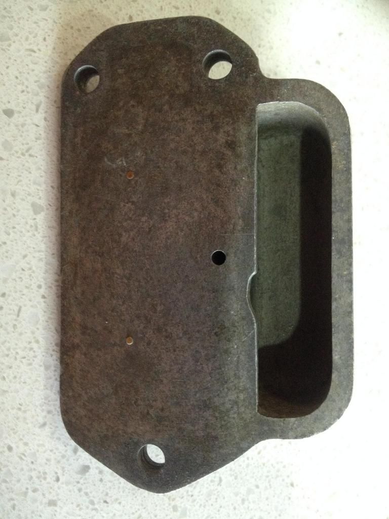
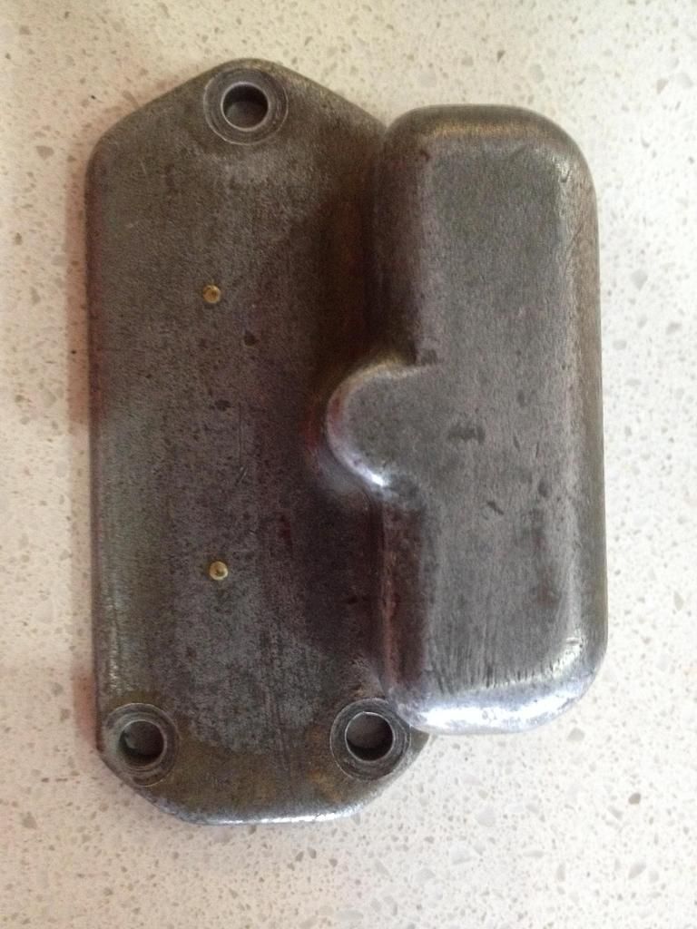
The float bowl lid also has two brass inserts, probably made by drilling holes and inserting brass rod. The purpose of the inserts, pictured below, is unknown.
http://i929.photobuc...zps10zu5pai.jpg
http://i929.photobuc...zpshmbqgbdm.jpg
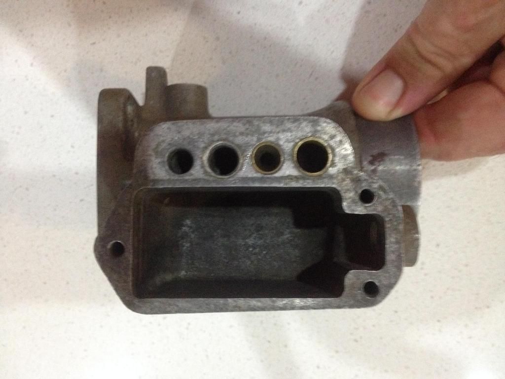
The integral-cast metering block has four vertical passages, shown in the image and drawing below.
http://i929.photobuc...zpswsr9xzix.jpg
http://s929.photobuc...zpspsnxkabv.jpg
The first passage, shown to the left of the image above, is an air-bleed inlet. Air passes through a brass mesh screen pressed into the side of the carburettor, which can be seen in the image below:
http://s929.photobuc...zpsiztt2hxb.jpg
The air flows through the brass mesh screen and upwards to fill the cavity between the metering block and float bowl lid. Note that the float bowl lid forms two separate compartments – a cavity above the float bowl, and a separate cavity above the metering block. From the metering block cavity, air is able to flow down each of the other three vertical passages, as shown by the red arrows in the image below:
http://s929.photobuc...zpsslrfxwsg.jpg
The second passage, shown second-to-left in the image above, is the main fuel discharge. An anti-siphon bleed is pressed into the top of the passage, as shown in yellow in the images above. The bottom of the passage is press-fitted with a mitred steel main discharge jet, which protrudes from the bottom of the metering block into the carburettor throat.
The third passage, shown third-to-left in the image above, is the main metering passage. The passage is connected to the fuel bowl by a cross-drilling located some 3/16” above the float bowl floor (shown by the black circle in the image above. The cross-drilling is fitted with a 0.0955” main metering jet. This is a rather large jet, being 3½ times the area of a typical grey motor Stromberg jet. This again points to the carburettors being set up for methanol. The main metering jets are Rochester, which are very similar to Holley. The difference is the threads – Rochester are ¼”-28UNF, whilst Holley are ¼”-32UNEF. Rochester made some sidedraught carburettors (the R and RC models), though these carburettors look nothing like them. The cross drilling is covered by a steel main metering jet plug, which are ½-20UNFx5/16” with an integral washer and 7/16”AF head. The top of the main metering passage is fitted with a screw-in main metering air-bleed, shown in pale green in the images above. The main metering air-bleed is 3/8-24UNFx3/8”, drilled to 0.039” diameter.
The fourth passage, shown to the right in the image above, is the idle passage. The bottom of the passage is press-fitted with a 0.093” internal diameter brass seat, shown in purple. The top of the passage is fitted with a screw-in idle air-bleed restriction, shown in dark green in the images above. The idle air-bleed restriction is 5/16-24UNFx1.05”. The idle air-bleed restriction is screwed into the idle passage, and bottoms out (seats) on the brass seat. The idle air-bleed (which controls the air flow) is drilled to 0.028” diameter. The idle emulsion-bleed is drilled to 0.033”. Whilst in theory this drilling should control the fuel flow, there is also a restriction where the air/fuel emulsion flows from the idle passage into the main carburettor throat. The carburettor throat has only been drilled to 0.038” diameter. Thus the combination of the 0.033” emulsion-bleed and 0.038” carburettor throat drilling will control fuel flow.
In addition, the four passages have been cross-drilled twice. The first cross-drilling, shown from the left of the images above at 11/32” below the top of the float bowl/metering block, connects the air-bleed inlet, main fuel discharge and main metering passages. However, the air-bleed inlet passage cross-drilling is blocked off with a brass sleeve, shown in orange in the images above. The second cross-drilling, shown from the right of the image above at 27/32” below the top of the float bowl/metering block, connects the main metering and idle passages. The first cross-drillings is sealed at the metering block edge with a drive plug, whilst the lower cross-drilling is sealed with a lead plug. The drive plug and lead plug are represented in blue in the images above.
Pictured below, from top to bottom, are the idle air-bleed, the main metering air-bleed and the main metering jet:
http://s929.photobuc...zpsezfafpu6.jpg
When the engine is at idle, the throttle plates are near closed, as shown in the left-hand image below.
http://s929.photobuc...zpsann53wlj.jpg
A strong vacuum is formed downstream of the throttle plates, and air flows into the engine in the direction of the purple arrow. At the idle position the throttle plates are located such that the idle passage drilling is exposed to engine vacuum. The vacuum causes fuel (shown in red in the middle image above) to be drawn from the float bowl, through the main metering jet and up the main metering passage. The fuel flows through the cross drilling, and up the idle passage before passing through the idle emulsion-bleed.
The tip of the idle air-bleed tube is submerged in fuel, and air is drawn in through the air-bleed, forming an emulsion in the idle passage. The idle air bleed also acts as a vent to prevent siphoning of fuel from the idle system at high speeds or when the engine is shut off. The emulsified fuel flows through the brass seat, and out into the carburettor throat. Because the idle emulsion-bleed (and idle carburettor throat drilling) is much smaller than the main metering jet, the fuel flow is controlled (metered) by the idle fuel restriction (and idle carburettor throat drilling). To change the idle quality, the idle emulsion-bleed can be made larger (making more fuel flow) or the idle air-bleed can be made larger (causing more air to flow, leaning out and emulsifying the fuel). Note however that if increasing the idle emulsion-bleed much larger, the idle carburettor throat drilling will soon become the restriction controlling idle fuel flow, and will also need to be increased in size.
As the throttle is opened further (as shown in the right-hand image above), the vacuum behind the throttle plates increases. Fuel continues to be drawn into the idle circuit, but is also pulled higher up the main metering circuit. The fuel thus flows from the fuel bowl, through the main metering jet, up the main metering passage, through the cross-drilling and down the main discharge passage. The tip of the main metering air-bleed tube is submerged in fuel, and air is drawn in through the air-bleed, forming an emulsion in the main discharge passage. The emulsified fuel flows through the mitred main discharge jet and out into the carburettor throat. The fuel flowing out the main discharge jet is controlled (metered) by the main discharge jet. To change the engine fuel quality, the main discharge jet can be made larger (making more fuel flow) or the main discharge air-bleed can be made larger (causing more air to flow, leaning out and emulsifying the fuel).
Of note, the carburettor has no transition, power or accelerator circuits. If the carburettor is snapped wide open from idle, a lot of air flows through the throttle plates. The engine leans out, and will either pause or lean backfire. Equally, as the carburettor is moved slowly from idle to wide open the carburettor will initially run on the idle circuit. The fuel mixture will lean out as the throttle plate is opened, up until the point that the main metering circuit begins to flow. At this point, the mixture will rapidly become richer. This performance will give a noticeable effect on engine speed/power when accelerating. With no power circuit there is a risk of insufficient fuel (and either loss of performance or pinging) under load. This would be controlled by running a main metering jet of sufficient richness to cover the worst case load. Realistically, the carburettor has been designed to be in only two states – idle, and flat-out. This makes it useful for drag racing and speedway use, though less useful for street or circuit racing.
The float level is set similarly to an EE Stromberg, by bending the brass tab on the end of the float. Care needs to be taken in setting float level as the cross-drilling between the idle discharge and main metering passages is quite low in the float bowl (exactly the middle). This means that if the fuel level rises above the 50% mark, the float bowl will overflow through the idle circuit (as shown in red in the image below).
http://s929.photobuc...zps5vpn4wjo.jpg
I’ve gone through and stripped down, cleaned and rebuilt the carburettors. The next step will be to make up some aluminium adaptors to adapt the 3-bolt flanges back to the SU 4-bolt pattern. I’ll then give the sidedraughts a test run on the twin-SU manifold on my test mule grey motor (the same manifold I ran the Howarth injection on). Like the Howarth injection, it appears that the sidedraughts are set up for methanol, and will overfuel on petrol. Pretty fair chance I set the driveway on fire again  .
.
My apologies that the images in the post above are links, and not displayed as pictures in this forum. I tried a couple of times, but failed to get the IMG link to work. Not sure why I have intermittent problems with this.
Cheers,
Harv


