PatWankel Rotary Engine
#1
Posted 21 December 2016 - 15:23
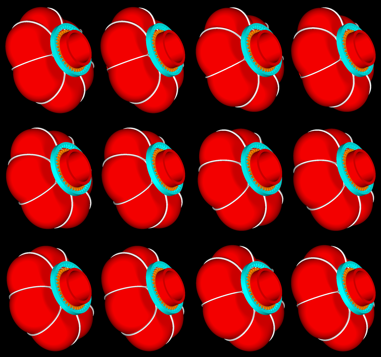
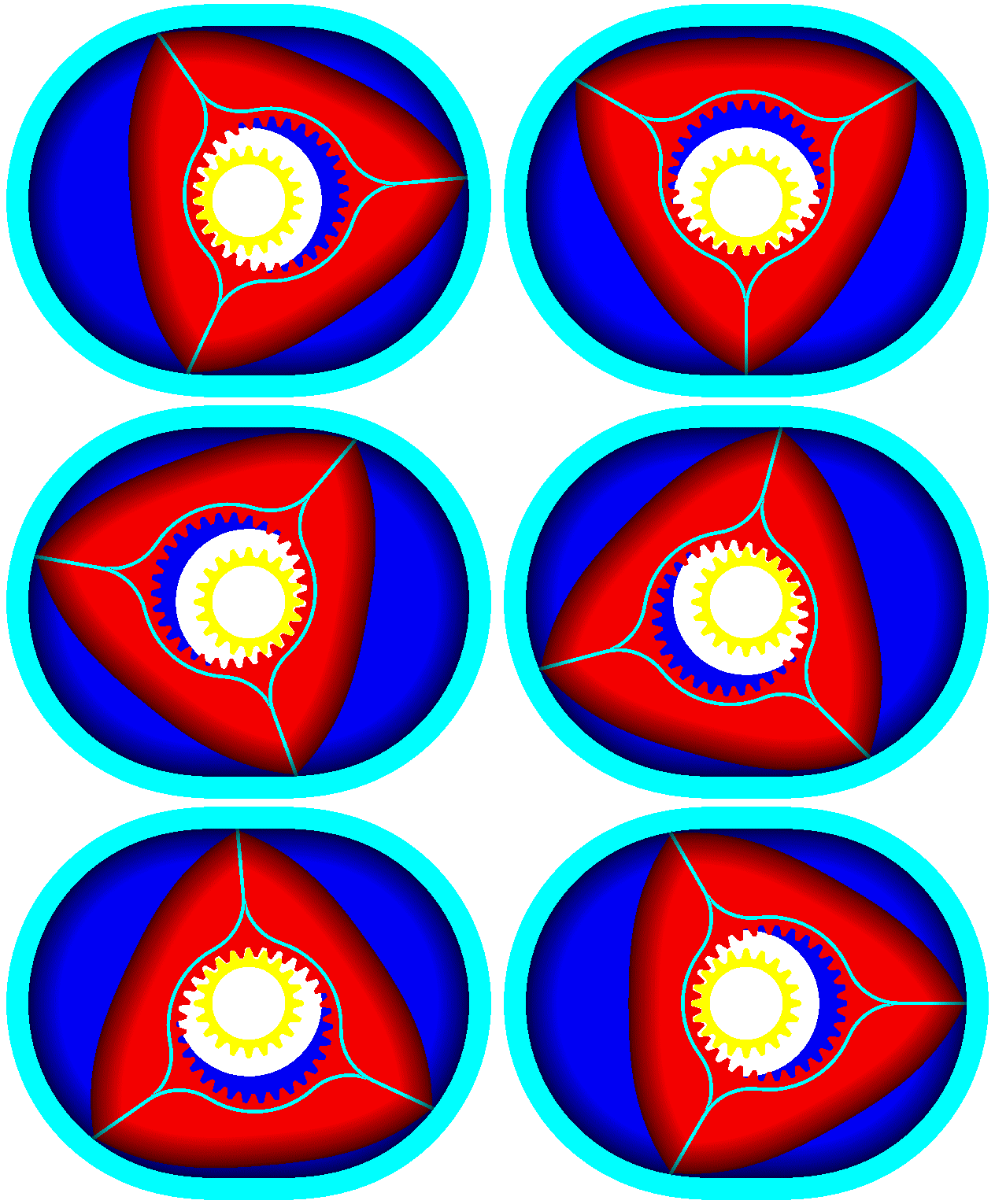
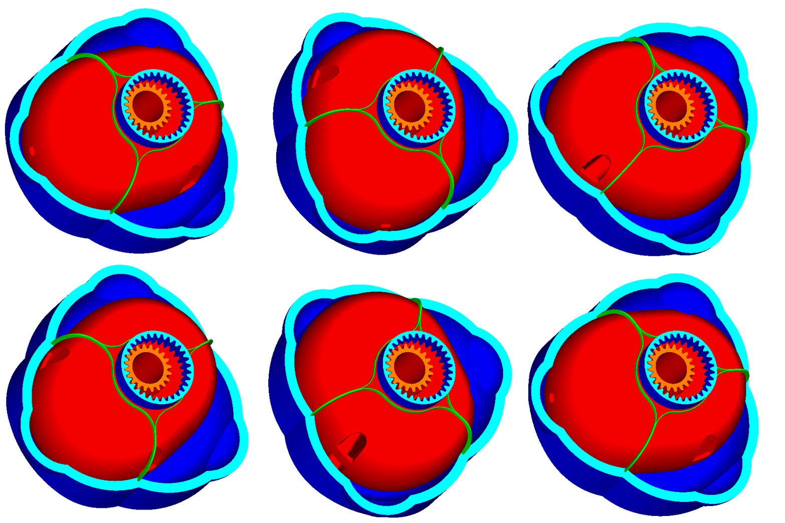
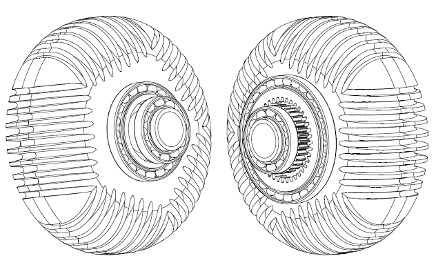
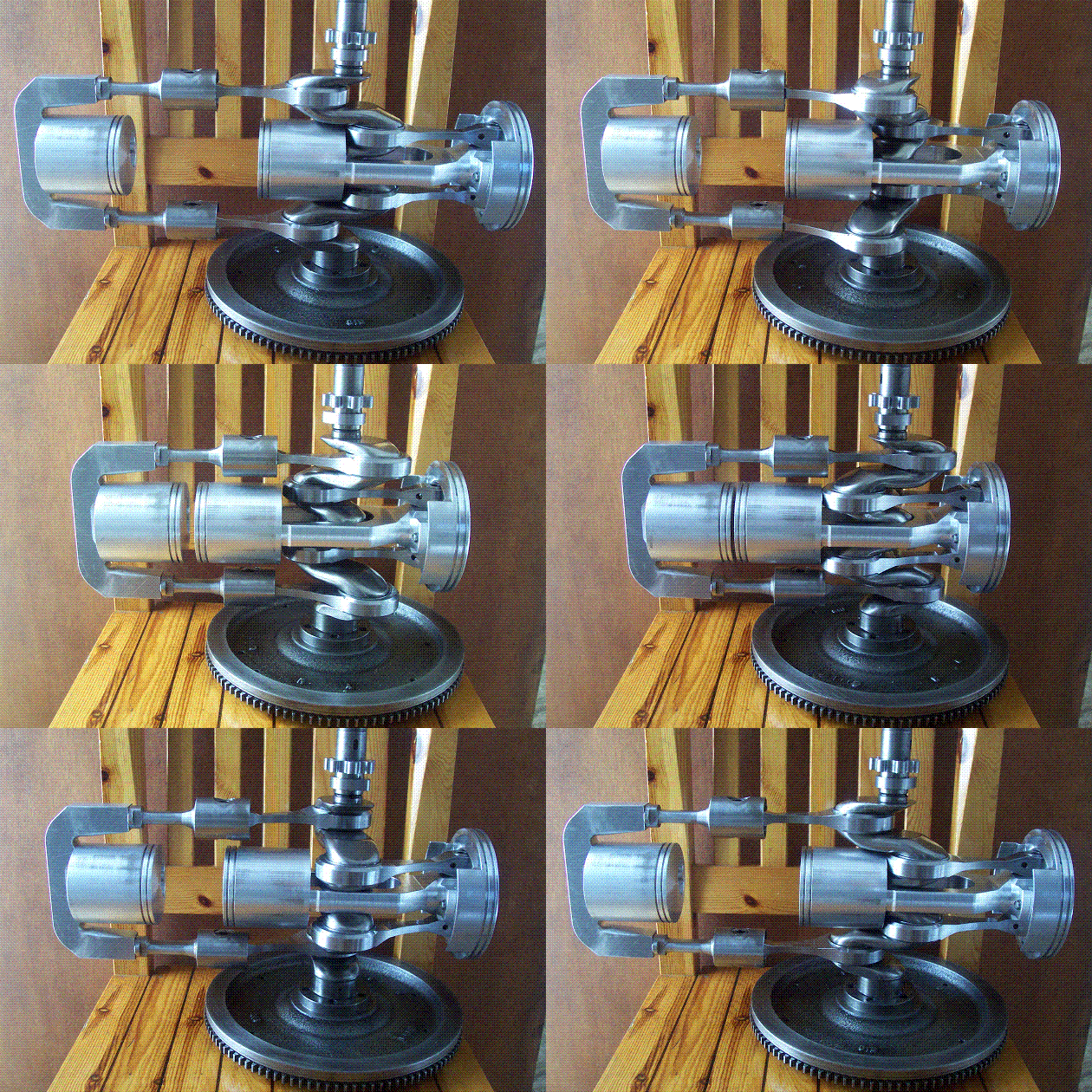
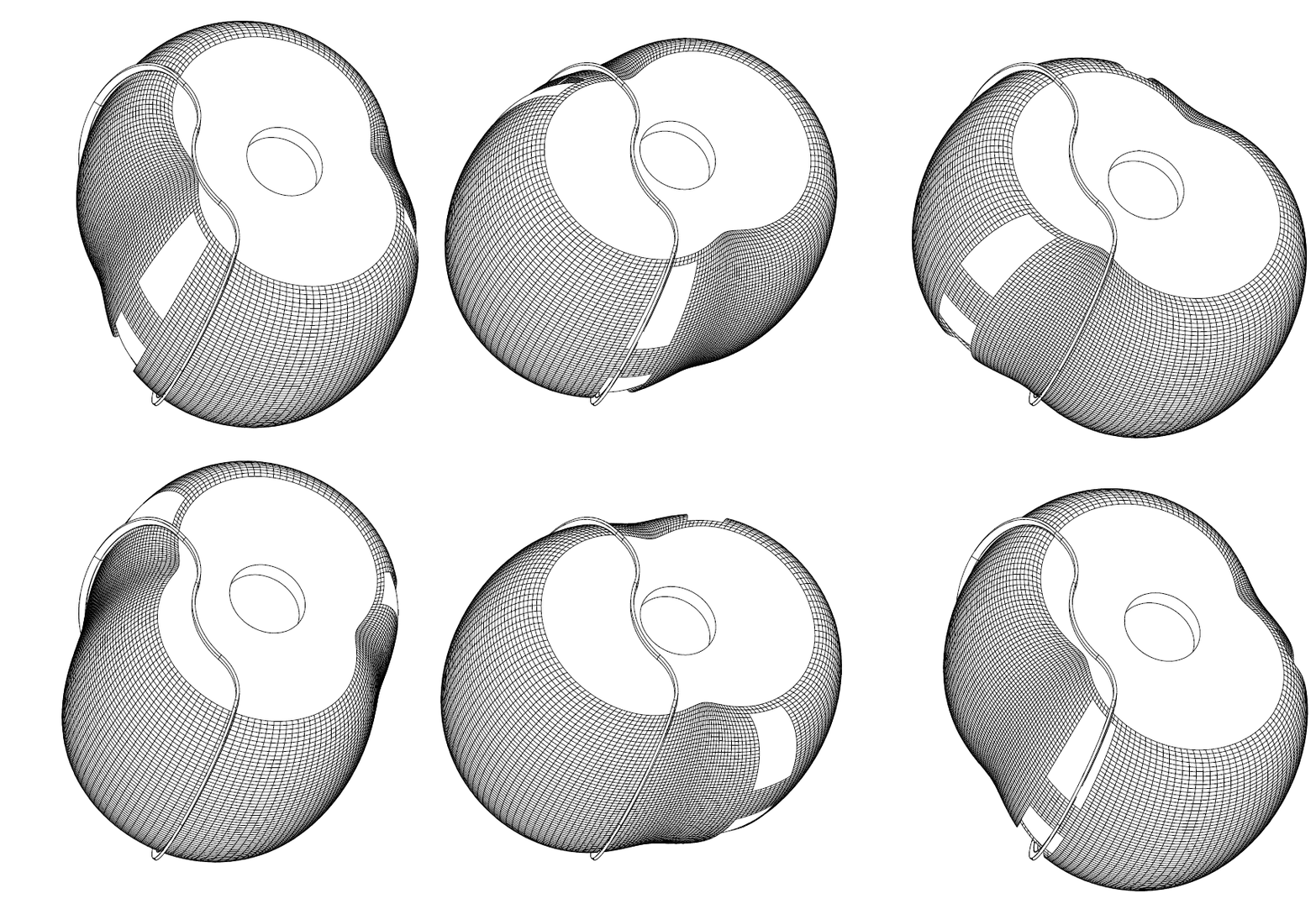
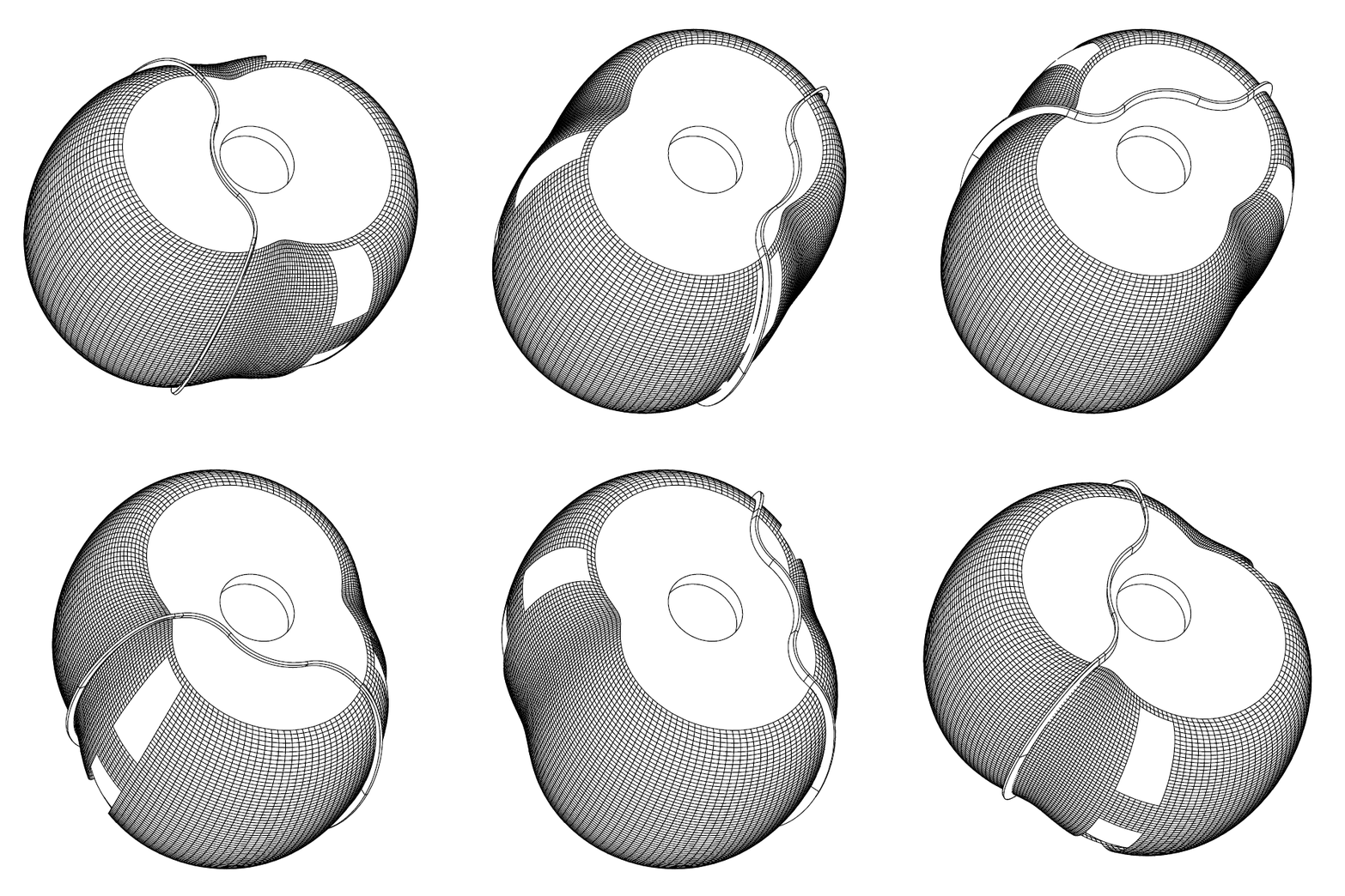
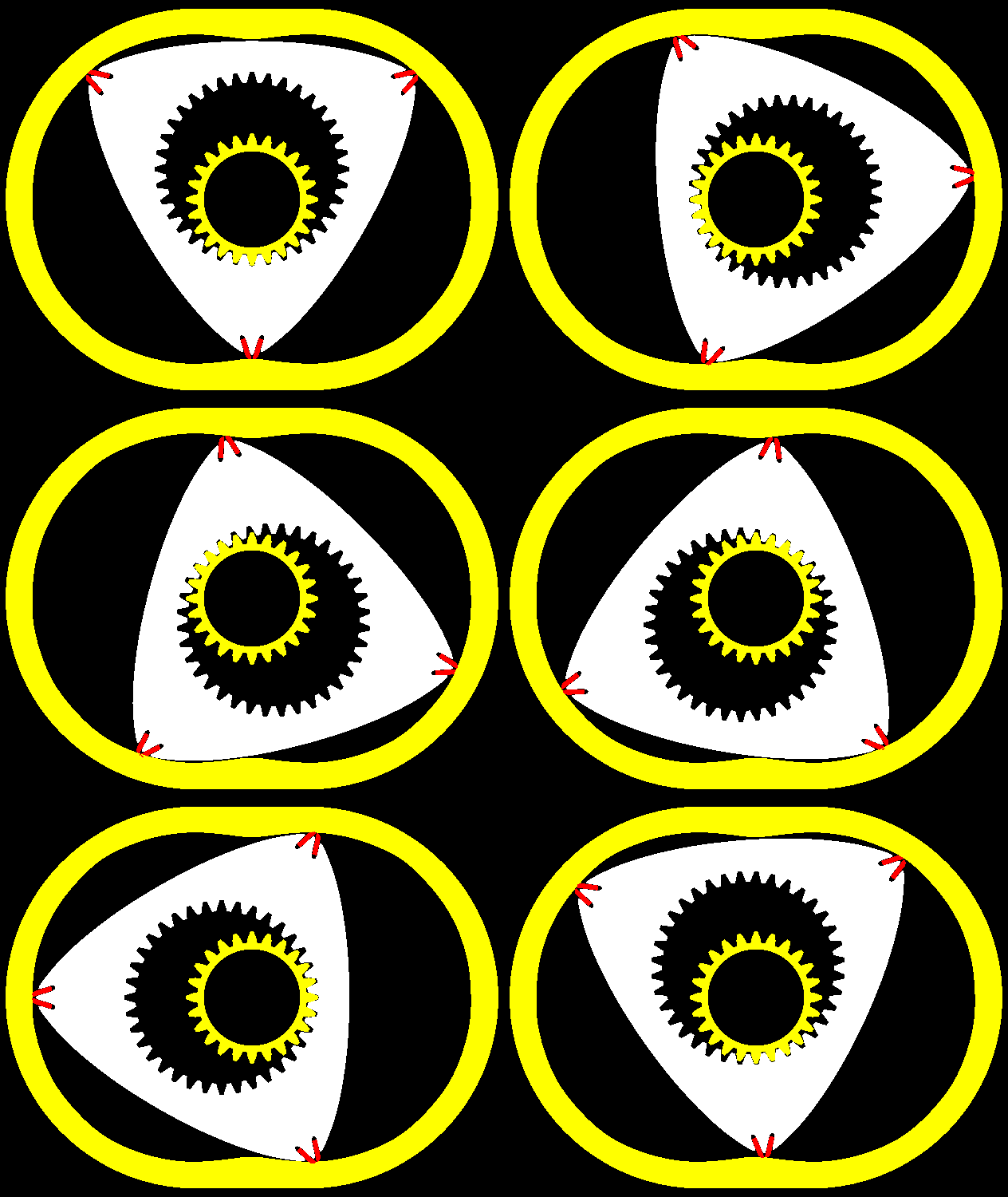
Here is a Wankel-like Rotary Engine:
The working surface whereon the seals abut is not a “cylindrical” surface but a 3D curved surface ending smoothly / tangentially on the side flat surfaces of the casing.
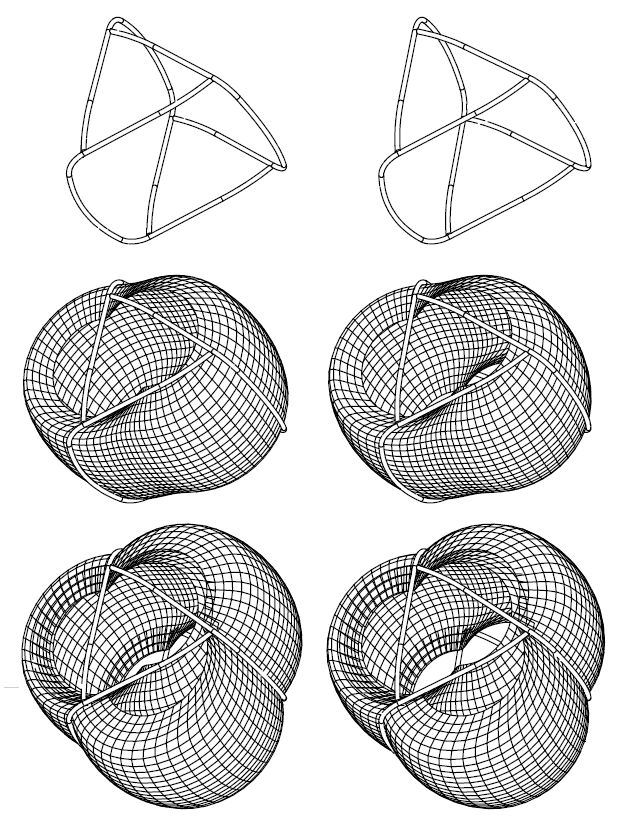
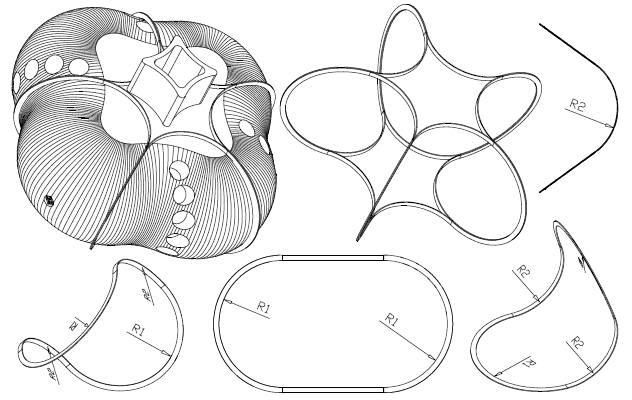
The typical “Wankel sealing grid” (wherein each combustion chamber is sealed by a set of two side seals, two apex seals and four button (or corner) seals) can be replaced by a single piece seal per combustion chamber.
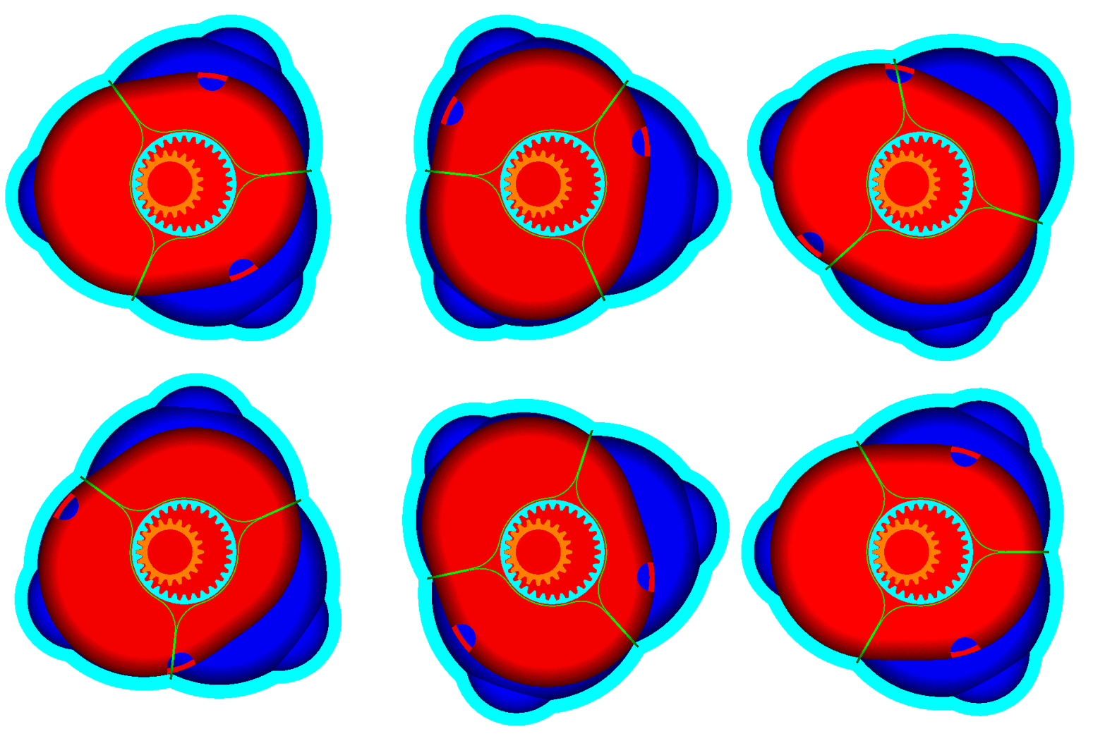
Here is a PatWankel wherein the working surface is on the inner body (say as in the Liquid Piston engine):
One seal per combustion chamber, as in the reciprocating piston engines.
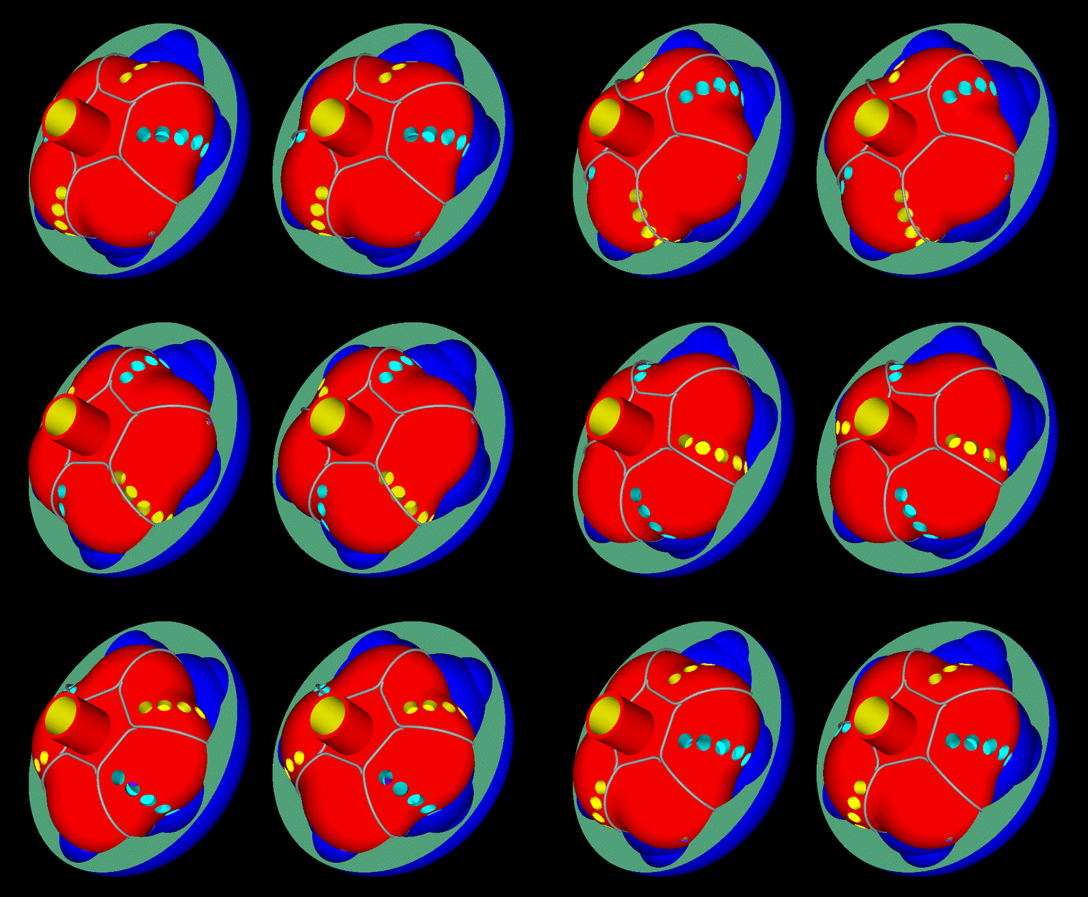
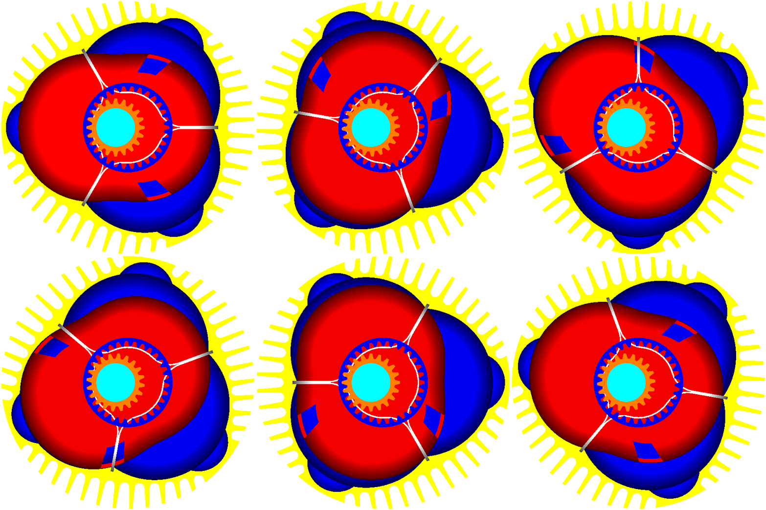
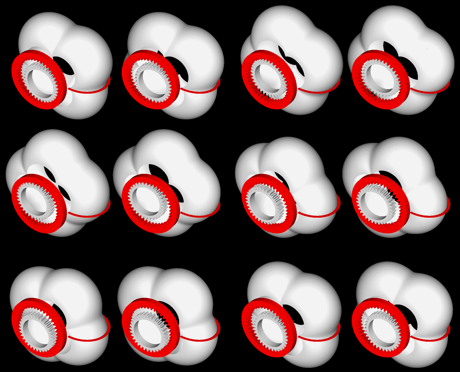
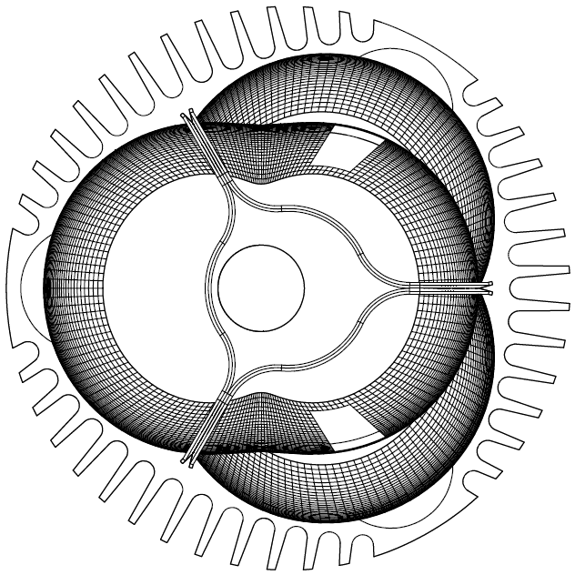
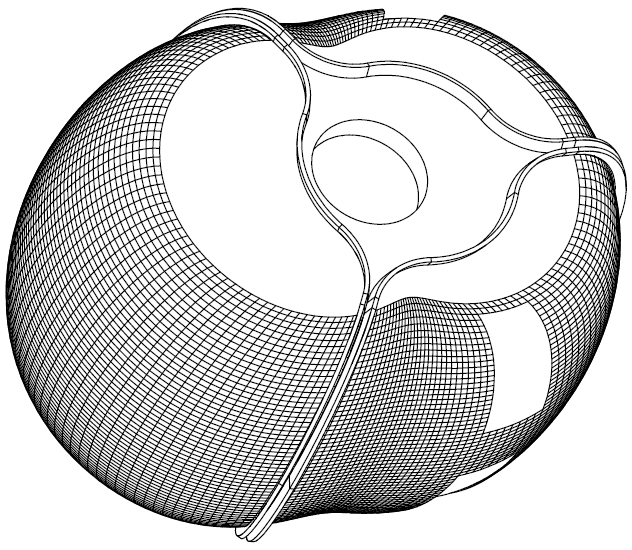
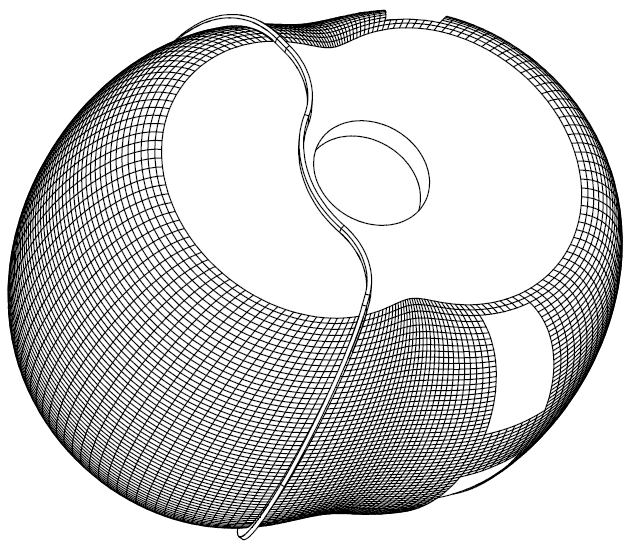
This five “cylinder” PatWankel rotary ( stereoscopic view, as at http://www.pattakon....Stereoscopy.htm ) :
has two combustions per rotation of the inner body, i.e. as much as a two-rotor Wankel Rotary (say, Mazda RX-8).
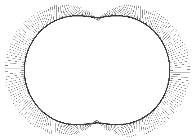
Does the oval seal at bottom middle remind the Honda NR750?
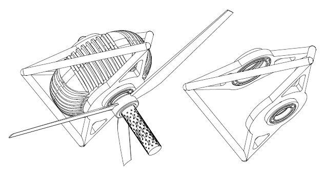
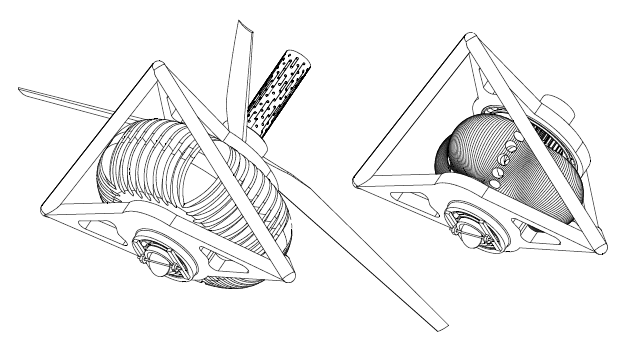
Imagine this PatWankel engine at the back of an airplane pushing forwards:
There is no eccentric shaft.
There are no balancing webs.
However it is perfectly balanced.
For more: http://www.pattakon....onPatWankel.htm
Thoughts?
Objections?
Thanks
Manolis Pattakos
Advertisement
#2
Posted 22 December 2016 - 08:59
Hallo Manolis
This is a interessting Idea but total unusable for big series. But almost all engine parts are very difficult und extremly expensiv.
And no manufacturer will investing in a expensiv/difficult engine without future.
Every good engineer knows the future and that is electric and not an difficult internal combustion engine.
The overall performance of an electric vehicle with battery is unbeatable as a combustion engine of any kind.
The rotary engine is death, except at mazda.
The oval piston engine Honda NR 750 was very very very expensiv and the advantage is much too small.
The technology was und is not profitable and your engine is much more expensive. The industry likes standards parts as cylinders, pistons, rods, springs, cranks and cams. But your difficult engine parts need a new production line that costs a lot of money. Nobody will build this
And if you do not believe it, then they will see it for yourselves.
I like your rotary valve motor much more, if not very.
best regards
Edited by Speedman, 22 December 2016 - 09:36.
#3
Posted 22 December 2016 - 23:21
I like the idea very much Manny. If I understand correctly it is basically an improved sealing system for a Wankel - using similar technology to a convention piston ring. But as with a "normal" ring you presumably need an expansion gap. Maybe you could use a stack of three flat-section sealing "rings" with staggered gaps. Also the gaps would make it easier to instal the sealing strips. This idea may give the Wankel a second life.
#4
Posted 23 December 2016 - 22:30
The old Brap Brap has always had 2 major problems, short life on seals and the biggy it is way too thirsty.
And as many will know the exhaust systems required to keep it quiet are expensive and heavy.
Mazda have done a good job persisting with the engine, The turbo ones as a standard engine go very well.
As a race engine they seem past their useby however. Still quite a few around racing with red hot exhausts but here in Oz the fast Mazdas are using a turbo 4 in RX3s!
And as always the problem with noise. Which will never be resolved though the 20B does sound a lot nicer in comparison to the earlier engines which was just harsh noise.
#5
Posted 24 December 2016 - 04:39
I like the idea very much Manny. If I understand correctly it is basically an improved sealing system for a Wankel - using similar technology to a convention piston ring. But as with a "normal" ring you presumably need an expansion gap. Maybe you could use a stack of three flat-section sealing "rings" with staggered gaps. Also the gaps would make it easier to instal the sealing strips. This idea may give the Wankel a second life.
I did have some further thoughts - the main case would be very tricky to machine.
Also - it is a fairly obvious idea - surely the various people who have tried to develop the Wankel over the years would have considered such a layout of sealing strips? - and apparently discarded the idea?
#6
Posted 27 December 2016 - 11:52
I think the following analysis and quotes can make clearer the reasoning behind the PatWankel engine.
In the conventional Wankel Rotary the flame sees way bigger surfaces (and has to travel along way longer distances) than in a conventional engine.
The surface to volume ratio during combustion, only partly explains the increased thermal loss and the emissions of the Wankel.
The high surface to volume ratio is one only of the issues of the conventional Wankel.
According the “Liquid Piston” at www.liquidpiston.com, their non-Wankel engine
runs closer to a constant volume combustion than the reciprocating piston engines.
Last year DARPA signed a $1M agreement with Liquid Piston.
Take the five “cylinder” PatWankel shown in the drawings / animation.
At TDC (i.e. wherein the volume of the working chamber is minimised) almost all the air / mixture entered into the working chamber is concentrated in a compact cavity (spherical or semi-spherical etc).
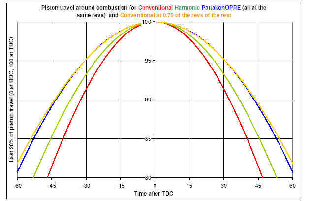
As compared with a Ducati Panigale 1299cc reciprocating piston engine running at the same revs with the revs of the inner body of the PatWankel, the PatWankel provides more than 40% additional time around the TDC (1.15*1.25=1.43)
The 15% longer dwell at the TDC comes from the harmonic (i.e. pure sinusoidal) variation of the combustion chamber volume:
the 1.25 comes from the 225 degrees required in order the chamber to go from its TDC to its BDC (wherein the volume is maximised):
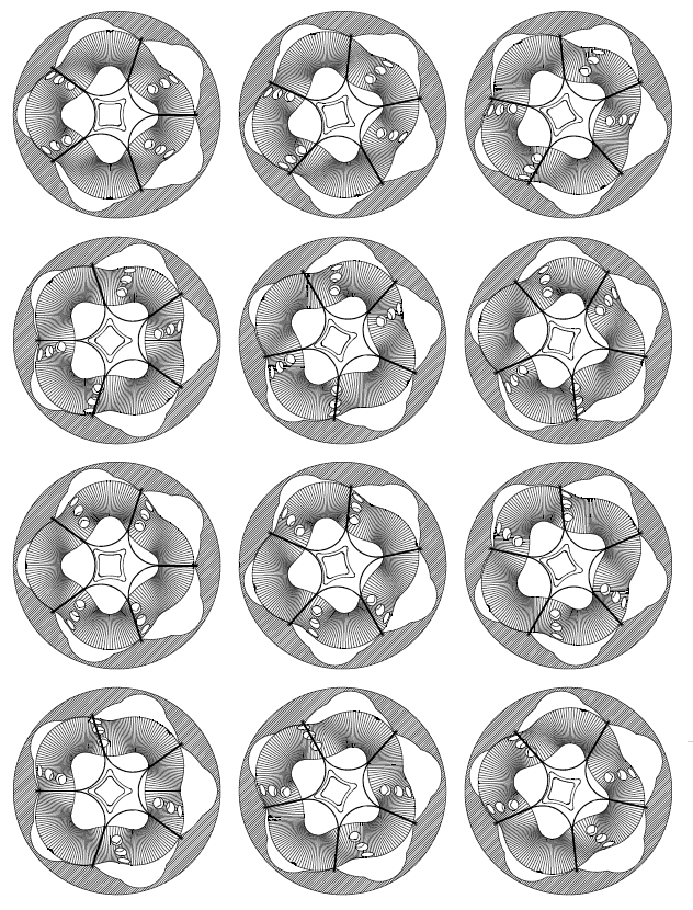
There is plenty of time, lots of squeeze and a very short distance for the flame to travel, enabling the combustion to actually complete inside the compact cavity.
Most of the thermal loss happens during the combustion.
The thermal loss continuous during the expansion, however the rate of thermal loss during the combustion is way higher.
Compare it with the thermal loss in a Ducati Panigale 1299 wherein the flame, during the combustion, sweeps the inner surfaces of a wide (116mm diameter) short (about 5mm height) cylinder (like a coin) having abnormal bottom and top (valve pockets etc).
Reasonably, the thermal loss towards the walls during the combustion will be substantially more than in the above PatWankel.
So, there are reasons for lower thermal loss in the PatWankel, despite the bigger (than in a reciprocating piston over-square engine) area of its wall surfaces.
Quote from:
http://gasturbinespo...ticleid=2467298
“Abstract
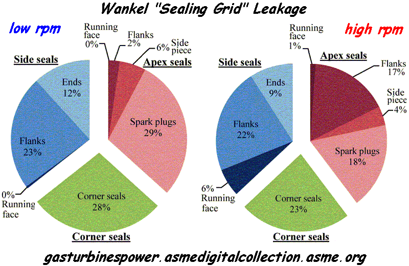
The Wankel rotary engine offers a greater power density than piston engines, but higher fuel consumption and hydrocarbon emissions, in large part due to poor gas sealing. This paper presents a model for the deformable dynamics of the side seal, which completes a set of modeling tools for the comprehensive assessment of the gas leakage mechanisms in the rotary engine. It is shown that the main leakage mechanisms for the side seals are: (1) opening of the inner flank due to the contact with the trailing corner seal, (2) flow through the gap with the leading corner seal, (3) simultaneous opening of both inner and outer flanks due to body force at high speed, and (4) running face leakage due to nonconformability at high speed. The leakage mechanisms are qualitatively validated at low speed with observed oil patterns on the rotor from laser-induced fluorescence (LIF) experiments. Finally, the predicted total leakage area for all the gas seals ranges from 1.5 mm2/chamber at low speeds to 2 mm2/chamber at high speeds, which is in agreement with the previous experimental studies, and the three gas seal types (side seals, apex seals, and corner seals) each accounts for about 1/3 of the total leakage, with minor variation as a function of speed.”
End of Quote
According the above abstract / plot, the leakage is a major problem / issue of the Wankel rotary engines.
Each cylinder of the Panigale 1299 has a capacity of 650cc, i.e. as much as each chamber of the Wankel RX-8.
Take a drill and make one hole of 1.5mm diameter (1.77mm2 area) on each piston crown of the Ducati Panigale, to allow each combustion chamber to communicate, through the hole, with the crankcase.
No doubt, the Panigale can still work, however a significant amount of high pressure gas will escape reducing the efficiency (a lot of energy is consumed to compress the gas that leaks without giving back any energy) and worsening the emissions.
This is the way the conventional Wankel works till now.
The gaps around each combustion chamber have an equivalent total leakage area of 1.5mm2 at low revs, to 2mm2 at high revs.
Compare the leakage from the “running surfaces” with the rest leakage.
Quote from http://energyresourc...ticleid=2522107
“Numerical Investigation on the Effects of Flame Propagation in Rotary Engine Performance With Leakage and Different Recess Shapes Using Three-Dimensional Computational Fluid Dynamics”
ABSTRACT
This study was carried out with an objective to develop a 3D simulation methodology for rotary engine combustion study and to investigate the effect of recess shapes on flame travel within the rotating combustion chamber and its effects on engine performance. The relative location of spark plugs with respect to the combustion chamber has significant effect on flame travel, affecting the overall engine performance. The computations were carried out with three different recess shapes using iso-octane (C8H18) fuel, and flame front propagation was studied at different widths from spark location.
Initially, a detailed leakage study was carried out and the flow fields were compared with available experimental results. The results for first recess with compression ratio 9.1 showed that the flow and vortex formations were similar to that of actual model. The capability of the 3D model to predict the combustion reaction rate precisely as that of practical engine is presented with comparison to experimental results. This study showed that the flame propagation is dominant toward the leading apex of the rotor chamber, and the air/fuel mixture region in the engine midplane, between the
two spark plugs, has very low flame propagation compared to the region in the vicinity of spark. The air/fuel mixture in midplane toward the leading apex burns partially and most of the mixture toward the trailing apex is left unburnt. Recommendations have been made for optimal positioning of the spark plugs along the lateral axis of the engine. In the comparison study with different recess shapes, lesser cavity length corresponding to a higher compression ratio (CR) of 9.6 showed faster flame propagation toward leading side. Also, mass trapped in working chamber reduced and developed higher burn rate and peak pressure resulting in better fuel conversion efficiency.
Third recess with lesser CR showed reduced burn rates and lower peak pressure.
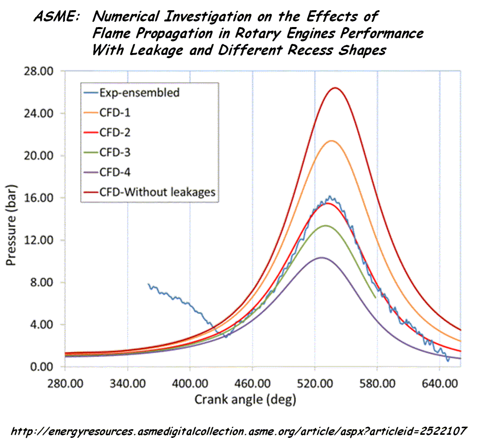
End of Quote.
It is more complicated than “surface to volume” ratio.
According the last plot, if the leakage is avoided, the same Wankel doubles its power, halving at the same time its brake specific fuel consumption (g/kWh).
The surface to volume area remains as high as before.
So, if we could reduce substantially the leakage in the conventional Wankel, an extreme increase of the power output and an extreme decrease of the BSFC are expected.
This is what the following PatWankel:
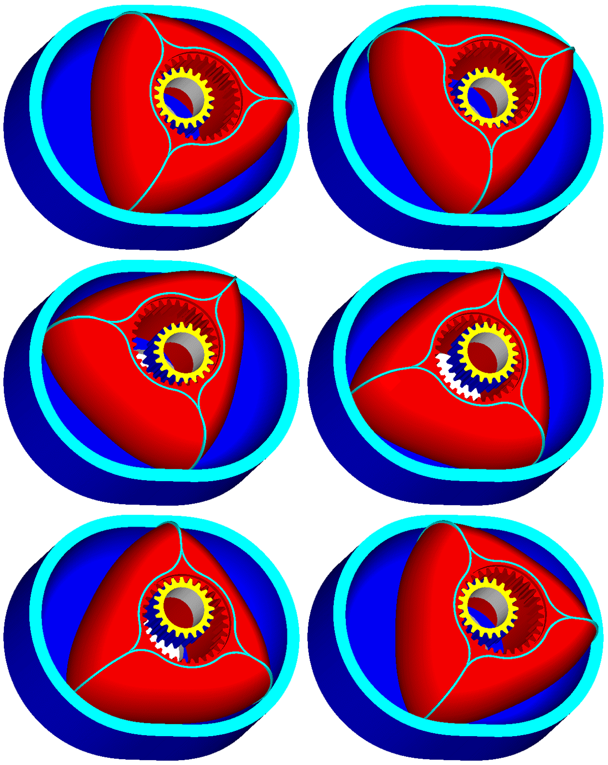
does: it reduces the gas leakage to levels met in the reciprocating piston engines.
If the plot of ASME is not wrong, the improvement (on the power output and on the mileage) on a Mazda RX-8 when modified to PatWankel would be unbelievable.
But there is more.
The other version of the PatWankel (the PatWankel wherein the seals slide onto the surface of the inner body) besides reducing the leakage it performs another significant “task”: it enables a compact combustion chamber to be formed, wherein almost all the mixture is concentrated and is burnt before the expansion.
This improvement may prove in practice more important than the significant reduction of the gas leakage.
The mechanical friction in a rotary engine like the PatWankel 5-cylinder is substantially lower than in an “equivalent” reciprocating piston engine.
There is no valve train.
There are no piston skirts to thrust on cylinder walls.
The four roller bearings on the frame and the sliding of the seals on the working surface are the only cause of mechanical friction.
All the energy / torque passes directly through the shaft of the inner body to the load.
The outer body receives no torque, at all.
If you count all these together (improved sealing, fast combustion into a compact cavity, reduced mechanical friction, simplicity etc) things get more than interesting.
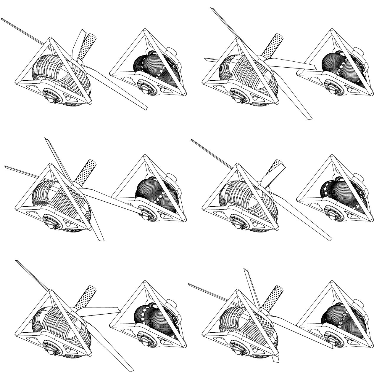
A five-chambers PatWankel in a Pusher airplane propulsion unit:
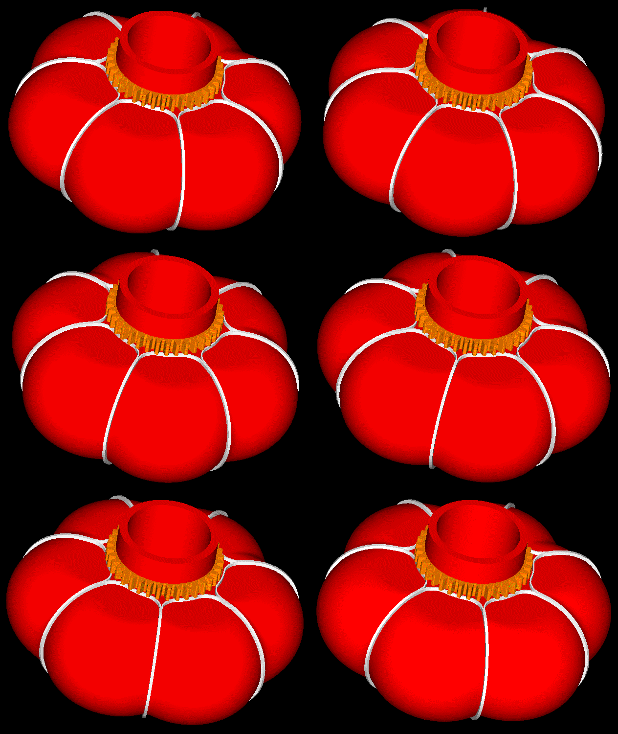
A seven-chamber PatWankel
Thanks
Manolis Pattakos
Edited by manolis, 27 December 2016 - 12:16.
#7
Posted 05 January 2017 - 05:15
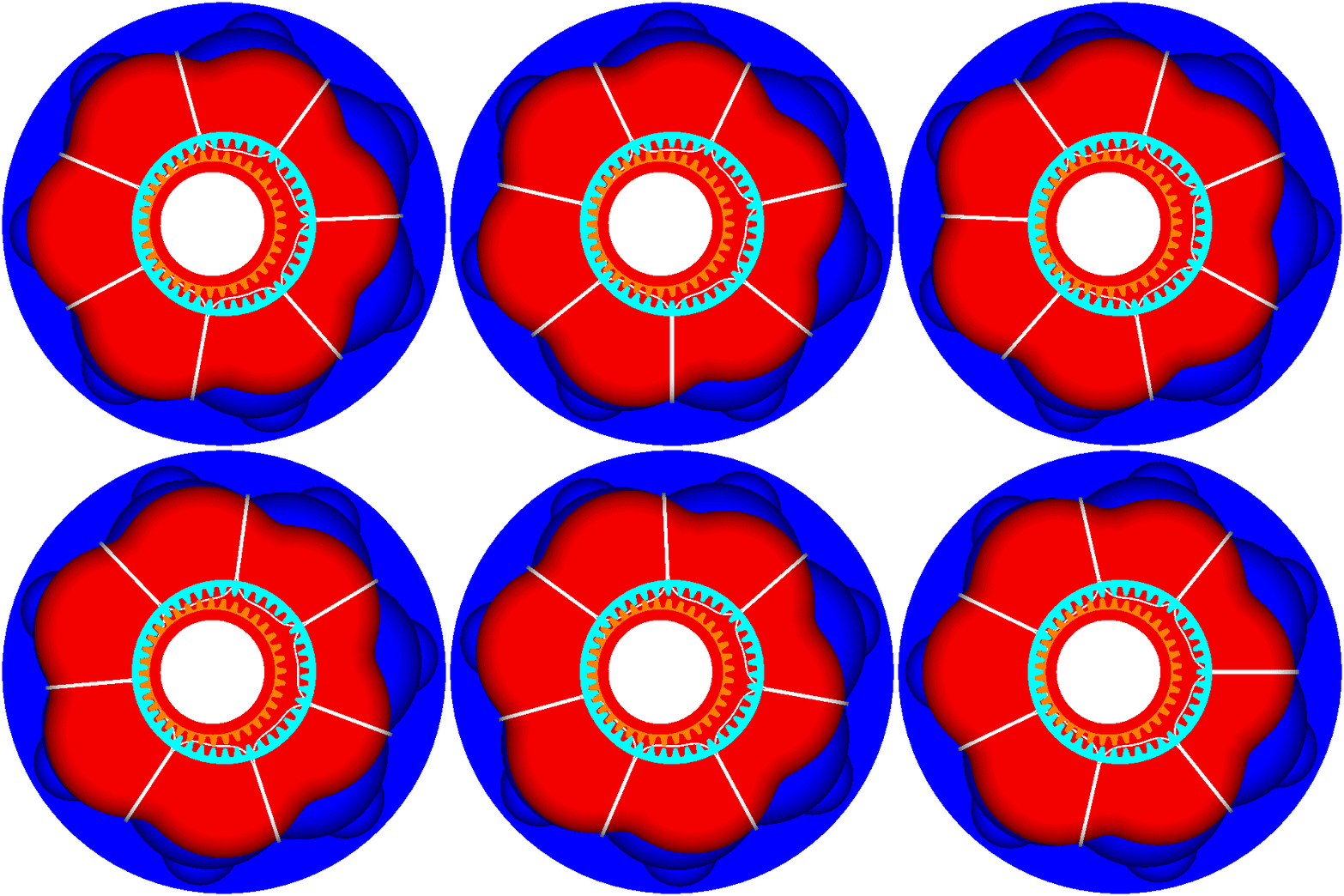
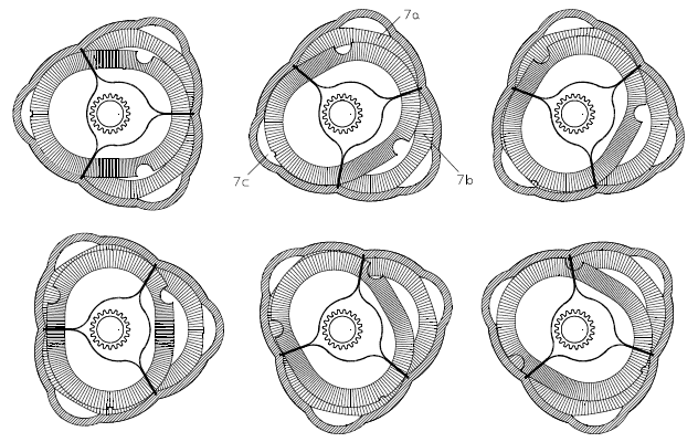
The following animation may-be useful for timing-check reasons:
The angle step is 10 degrees (as in the conventional engine, 180 degrees separate the TDC (wherein the volume of a working chamber is minimized) to BDC (wherein the volume of the same working chamber is maximized).
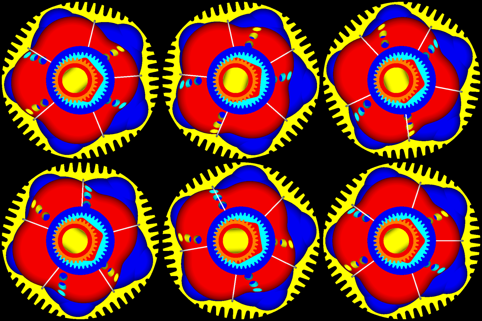
Start counting “frames” (and degrees) the moment the inner body is “horizontal” with the ports at right.
The timing shown is conservative.
The “overlap” may seem big, but it is quite small. This is so because during the “overlap” either the intake ports, or the exhaust ports, or both, are almost closed by the inner surface of the outer body.
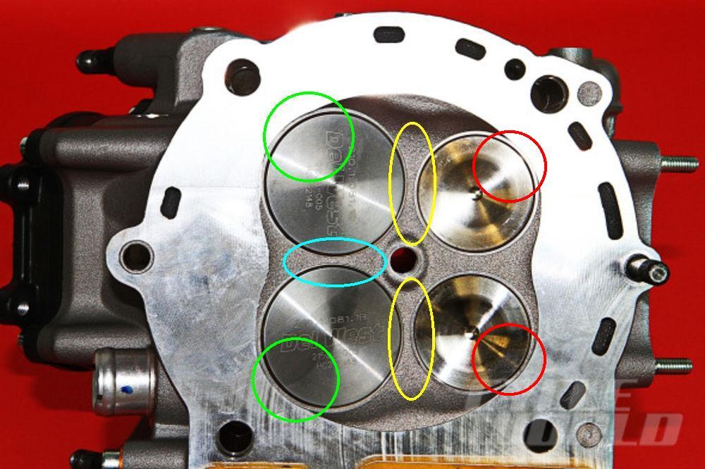
The overlap in this engine is way different than in a, say, Ducati Panigale:
wherein overlap means, more or less, the “short circuit” between the intake and the exhaust (the area marked by the yellow ellipses) and inevitable loss of unburned mixture,
while in the above PatWankel overlap means a through or uniflow “scavenging” of the chamber by the fresh charge (more or less as in the opposed piston engines) that sweeps / pushes out the burned gas and reducing this way the residual gas.
Thanks
Manolis Pattakos
#8
Posted 05 January 2017 - 23:58
According the last plot, if the leakage is avoided, the same Wankel doubles its power, halving at the same time its brake specific fuel consumption (g/kWh).
If the plot of ASME is not wrong, the improvement (on the power output and on the mileage) on a Mazda RX-8 when modified to PatWankel would be unbelievable.
No way improved sealing would have such a dramatic effect.
#9
Posted 06 January 2017 - 06:27
You write: “No way improved sealing would have such a dramatic effect.”
You are right.
I exaggerated to make it more interesting and have some technical objections.
But, let’s make a few calculations to take an idea of the difference.
With a hole / orifice having 1.5mm2 area, and a mean pressure difference of 20bar, the leakage rate is about 0.25m3/min (or 4lt/sec, or 4,000cc/sec) of gas at normal conditions.
Take the one only working chamber of a Wankel RX-8 running at 2,000rpm and follow its operation.
In order a cycle to complete in the specific chamber, they are required 3*360=1,080 degrees of rotation of the eccentric shaft (which correspond to a complete rotation of the rotor about its axis).
For 270 degrees of the eccentric shaft rotation (the 1/4 of the total time) the pressure is high in the chamber, causing significant leakage through the “equivalent” leakage hole.
In a time interval of 0.0225sec (it corresponds to 270 degrees of the eccentric shaft rotating at 2,000rpm) the above leakage rate of 4,000cc/sec gives 90cc per cycle per chamber, which corresponds to about 15% of the capacity of the chamber.
The energy provided during expansion by the rest 85% of the gas (i.e. the gas that remains into the chamber) is not 85%, but less because a part of the provided energy was consumed to compress the gas that leaks without offering mechanical energy.
We are already below 80% of the power the same engine would provide without leakage.
Now it comes the duration and efficiency of the combustion.
The combustion proceeds at slow rates and is incomplete.
The surfaces the flame sees during the combustion (i.e. during the period the rate of thermal loss is at its peak) is very large.
The compression ratio is necessarily low.
Liquid Piston claims that their non-Wankel engine completes the combustion inside the hemispherical compact cavity at the “top” of the combustion chamber.
The Liquid Piston engine, just like the Wankel engine, has harmonic (pure sinusoidal) expansion, which provides additional “dwell” around the combustion dead center.
It is also the fact that the Liquid Piston, as the Wankel, proceeds 1.5 times slower than a reciprocating piston engine running at the same rpm (the conventional needs 720degrees to complete a cycle of operation, the other two need 1,080 degrees of their eccentric shaft).
So, the Liquid Piston (as the PatWankel with the working surface on the inner body) keeps the mixture inside the cavity at the “top” of the chamber for almost 50% more time than in a conventional engine running at the same rpm, which gives a good chance to the combustion to complete inside the cavity (Liquid Piston calls it “constant volume combustion”).
This also allows the significant increase of the compression ratio relative to the conventional Wankel (which also means more power).
At high revs the inertia of the heavy and eccentrically moving rotors and the inertia of the apex seals:
and the flexing of the eccentric shaft limit the power of the Wankel.
The Wankel RX-8 has its peak power at 8,200 rpm (Max RPM: 9,400).
The capacity of each combustion chamber of the RX-8 Wankel is 654cc, i.e. as large as the capacity of each combustion chamber of the Ducati Panigalle 1299 which makes its peak power at 10,500 rpm and has the rev limiter at 11,500rpm.
Worth thinking: the reciprocating engine with the poppet valves making its peak power at 25% higher revs than the “valve-less” rotary engine!
Now think of a PatWankel (the version with the working surface on the inner body and the seals in grooves of the outer body) having 650cc per combustion chamber and running at 25% higher revs than the Panigale 1299, or 50% higher revs than the Mazda RX-8.
The inner body of the PatWankel performs a pure spinning (at constant angular speed) about a fixed axis, the outer body performs a pure spinning (also at constant angular speed, as in a turbine) about another fixed axis, the seals undergo a constant centrifugal acceleration (which reduces the force on the working surface at higher revs).
Taking all the previous into account (way better sealing, faster / complete combustion at higher compression ratio, substantially reduced thermal loss, higher revs etc), it seems it can double the peak power of the Wankel.
Thanks
Manolis Pattakos
#10
Posted 08 January 2017 - 23:00
Worth thinking: the reciprocating engine with the poppet valves making its peak power at 25% higher revs than the “valve-less” rotary engine!
It is worse than that. The Ducati is executing 10,500/2 = 5,250 cycles per minute while the Wankel executes 8,200/3 = 2,733 cycles per minute. The Ducati therefore makes peak power at 92% higher "revs" (true engine speed).
#11
Posted 11 January 2017 - 06:56
Last month LiquiddPiston received another $2.5 million from DARPA for their rotary Reverse-Wankel engine ($3.5 million so far).
More interesting: LiquidPiston also received a $25,000 cash prize from Shikorsky along with the opportunity to explore opportunities for LiquidPiston's technology with the Shikorsky product line
Thanks
Manolis Pattakos
#12
Posted 13 January 2017 - 14:28
Talking for the sealing in the Wankel, LiquidPiston and PatWankel rotary engines, here are some interesting, I hope, details:
With their different arrangement of the seals, LiquidPiston creates new “sealing” problems (not existing in the Wankel engine).
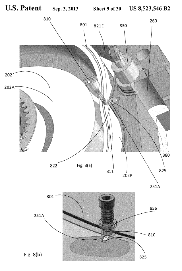
According the following drawing (from the patent of LiquidPiston):
there is an immovable “peak” seal, 825, which abuts on the cylindrical working surface 202R of the inner body,
there is also a side seal, 801, in a groove of the inner body, which follows the motion of the inner body.
A LiquidPiston side seal, as the seals of the conventional Wankel, undergoes a substantially variable (in direction and in amplitude) acceleration around the seal and around the cycle.
Here is the inertia force an apex seal of a conventional Wankel applies to the epitrochoidal casing :
(at some angles the inertia vectors outwards, at some other angles it vectors inwards),
and here is the acceleration required in order a point at the top edge (the outmost edge) of the side seal of a LiquidPiston engine to follow the motion imposed by the spinning / orbiting rotor:
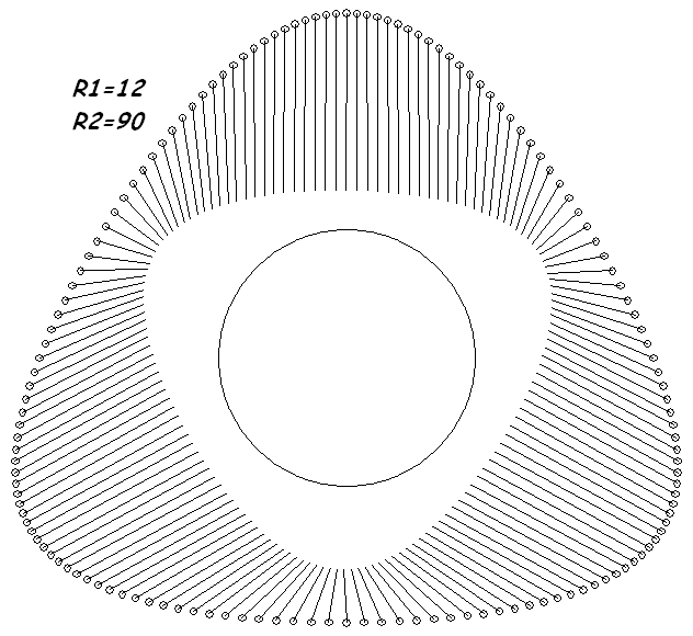
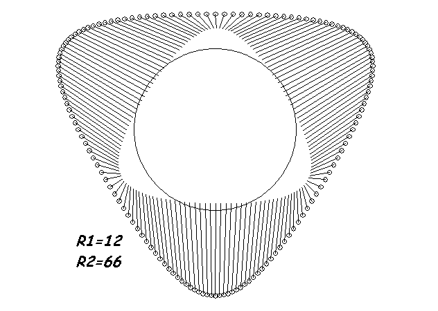
and here it is shown, for comparison, the acceleration required in order a point at the innermost edge of the side seal of a LiquidPiston engine to follow the motion imposed by the spinning / orbiting rotor:
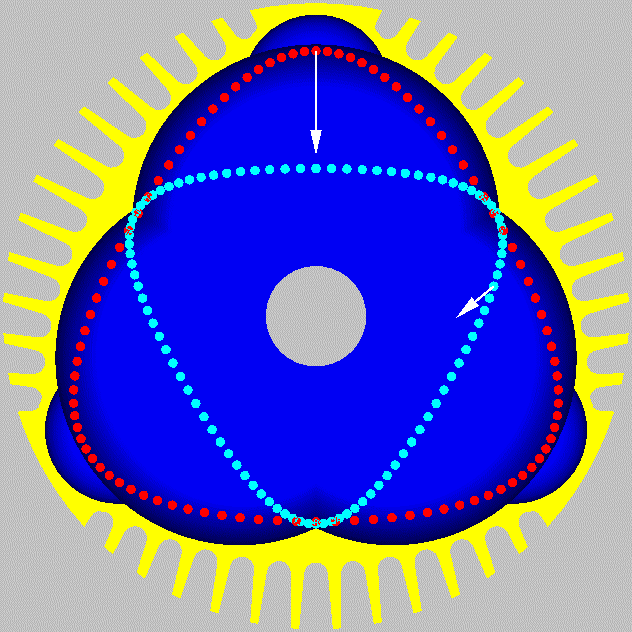
The following drawing helps in understanding the previous plots (the red circles show the path the outmost edge of the side seal follows, the cyan circles show the path the innermost edge of the side seal follows) :
R1 is the "crank-arm" of the eccentric shaft, R2 is the distance of the specific point of the seal from the center of the rotor.
In the LiquidPiston the casing (blue, yellow) is stationary. The rotor (not shown) performs a combined spinning-and-orbiting motion.
The gaps between the apex-seals /corner-seals / side-seals of the Wankel engine are gaps between bodies moving together (they are all inside grooves / holes of the rotor).
In the LiquidPiston, the side seal moves together with the inner body (the rotor), while the rest seals are stationary.
Any clearance of the synchronizing gear-wheels,
and any clearance in the bearings supporting the rotor (the bearing by which the rotor is rotatably mounted on the eccentric shaft and the bearings by which the eccentric shaft is rotatably mounted on the immovable casing),
and any “play” of the side seal inside its groove,
and any flexing of the eccentric shaft (or power shaft) due to inertia and/or combustion loads,
all are added to the required gap between the side seal and the “button seal”.
Note: around each chamber there are four such gaps.
The result is even more gas leakage than in the conventional Wankel.
Now think how the seals are arranged and are working in the PatWankel:
In the PatWankel with the working surface on the inner body, all the seals are inside grooves made on the outer body and perform a pure rotation (during a cycle, the inertia force remains constant in direction and constant in amplitude). Etc.
By the way, without an eccentric shaft, there is no flexing of the eccentric shaft.
Without inertia loads on the bearings, the clearance between the inner and the outer bodies is smaller.
Without eccentric shaft, no balance webs are required.
Thanks
Manolis Pattakos
#13
Posted 23 January 2017 - 08:55
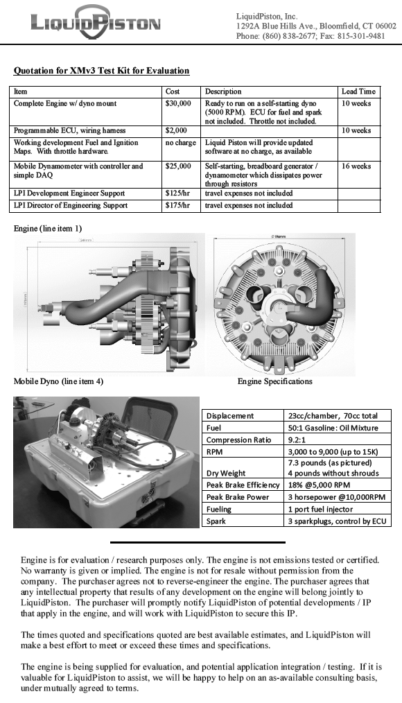
Here are the specifications of the XMv3 of LiquidPiston:
According the famous MIT university, the DARPA and the more than famous Shikorsky company, it is a promising engine design.
Here are a few calculations based on the above specifications and on the way the XMv3 operates.
They are required two only rotations of the eccentric shaft in order a combustion to take place in each working chamber (of the three existing). This means 1.5 combustion per eccentric shaft rotation.
In comparison, in a Wankel they are required three eccentric shaft rotations in order a combustion to take place in each working chamber (of the three existing). This means one only combustion per eccentric shaft rotation.
More combustions per shaft rotation sounds great.
However there is a significant side effect:
In the Liquid Piston the synchronizing gearing is heavily loaded by the combustion pressure.
Depending on the angle of the eccentric shaft, the teeth of the two gearwheels take a good percentage of the force acting on the “rotor” due to the high pressure gas.
In comparison the synchronizing gearing of a Wankel runs unloaded for as long as the engine runs at constant rpm.
At 10,000rpm the power output of the XMv3 is 3PS.
According the previous, 10,000rpm means 5,000combustions per working chamber of the XMv3.
Unless I am wrong, this is equivalent to a 70cc 4-stroke reciprocating piston engine operating at 10,000rpm (because it also burns 5,000 times the mixture contained in a chamber of 70cc).
A good 4-stroke makes more than 100mN of torque per lit (1,000cc) of displacement (even at the peak power revs).
This way, a torque of 7mN from a 4-stroke 70cc reciprocating piston engine is reasonable.
7mN at 10,000rpm means a power output of 14*7mN*10= 10PS.
This is more than 300% more than what the XMv3 makes.
Do I miss something?
Thanks
Manolis Pattakos
#14
Posted 24 January 2017 - 05:14
So the BMEP at peak power is only 30% of a 4T piston engine?
Probably a better way to compare is BTE, size per HP and weight per HP.
#15
Posted 24 January 2017 - 07:15
At http://papers.sae.org/2015-32-0719/ (SAE paper) they talk for 5bar indicated mean effective pressure (IMEP) and 1bar friction mean effective pressure (FMEP).
For an engine like the XMv3 of LiquidPiston, the 1bar FMEP seems too high (there are no piston skirts to thrust on cylinder liners, there is only one seal per combustion chamber (the only thing that slides and creates significant friction), etc).
By the way:
the Ducati Panigale1199 makes 106mN of torque per liter of displacement at its peak power,
the Wankel RX-8 Renesis makes 76mN of torque per liter of displacement at its peak power (72% of the Panigale),
the XMv3 of LiquidPiston makes 32mN of torque per liter of displacement at its peak power (30% of the Panigale).
By the way, the Ducati runs at way higher BTE than the other two.
Any thoughts?
What causes such a dramatic fall of the specific torque?
Thanks
Manolis Pattakos
#16
Posted 24 January 2017 - 07:21
You write:
“This is a interessting Idea but total unusable for big series. But almost all engine parts are very difficult und extremly expensiv.”
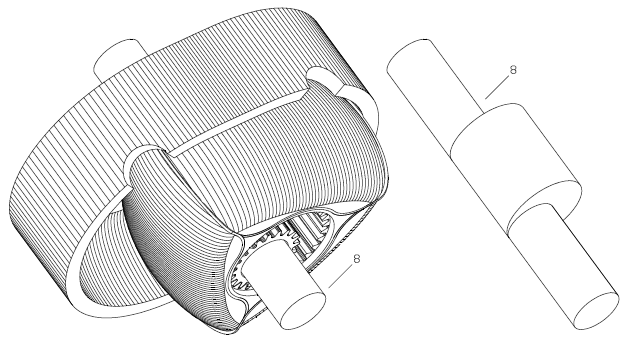
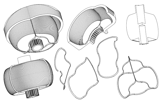
Here is the inner body of the five-“cylinder” PatWankel rotary engine and the way to cut it in a lathe:
(instructions in how to see it stereoscopically at http://www.pattakon....Stereoscopy.htm )
At operation it would be like:
Regarding the machining of the working surface (the only surface that needs high accuracy) :
On the chock of a lathe it is secured eccentrically a shaft.
The red gearwheel is secured immovable on the lath bed.
The body with its gearwheel (white) is rotatably mounted on the shaft.
As the chock rotates, the body to be machined performs a combined motion (it spins about the shaft and it orbits together with the shaft).
Given the shape of the seals to be used (the simplest form? the circular), the cutting tool has to follow a specific “path” (like half circle, for instance) in order to create / form the working surface on the part (the working surface is whereon the seals will abut and slide during operation; the seals are mounted in grooves made on the outer body).
In case of seals having simple form, even a conventional (not CNC) lathe can be used.
Similarly for the honing / polishing.
Do you see any problems?
Does it seem an expensive procedure?
Does it needs special/expensive tools?
Thanks
Manolis Pattakos
#17
Posted 25 January 2017 - 02:10
Any thoughts?
What causes such a dramatic fall of the specific torque?
Thanks
Manolis Pattakos
The quoted BTE of 18% gives us a clue. If the low BMEP was simply due to inefficiency or friction, the BTE would suffer. 18% is not great, but not terrible either for a small engine. The cause has to be low fuel mass flow which would be a result of very lean mixture or low VE.
Edited by gruntguru, 25 January 2017 - 03:31.
#18
Posted 25 January 2017 - 05:25
You write:
“The quoted BTE of 18% gives us a clue. If the low BMEP was simply due to inefficiency or friction, the BTE would suffer. 18% is not great, but not terrible either for a small engine. The cause has to be low fuel mass flow which would be a result of very lean mixture or low VE.”
According LiquidPiston specifications, their XMv3 engine is not emissions compliant.
So the question turns to : why to run their engine on very lean mixture at peak power?
As for the Volumetric Efficiency, they say that their engine will make 5PS at 15,000rpm, which means it can breath efficiently at 50% higher revs.
Something does not fit.
There are other things that do not fit, too.
The combustion in the five-“cylinder” PatWankel whose inner body machining is shown in a previous post is not a “constant volume combustion”.
LiquidPiston web site regularly mentions the constant volume combustion as a characteristic of their engines.
They are wrong.
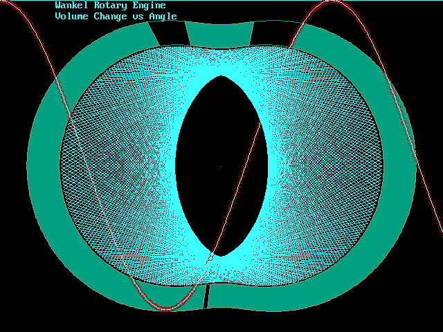
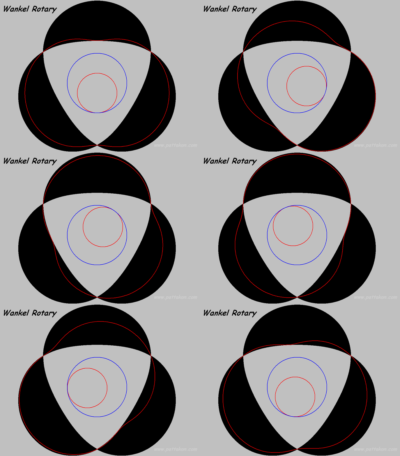
The relation between the volume in a working chamber of the LiquidPiston (say, in their XMv3 model) and the eccentric-shaft angle is pure sinusoidal (which is also the case for the Wankel):
Based on the above animation, it is easily understood why, if the Wankel has pure sinusoidal “volume vs angle” relation (this is what the first plot shows), the LiquidPiston is also “sinusoidal” as regards its “volume vs power-shaft-angle”.
You can’t have a “constant volume combustion” in an XMv3 engine, or, more correctly, in a Colley engine design; unless you add auxiliary chambers and pistons like the (850) in this patent of LiquidPiston:
But then it is not a rotary engine, any longer.
If it is accepted that the real LiquidPiston rotary engines do run on a “constant volume combustion”, then how can it be called the combustion in a PatOP engine:
https://www.youtube....h?v=2ByEgfTTq1I
wherein the volume-vs-angle (the blue curve in the following plot) varies, around the combustion dead center, substantially slower than “sinusoidal” (the green curve according which the LiquidPiston runs)?
We should call it “decreasing volume combustion”?
This is just nonsense.
The thermodynamic cycle LiquidPiston claims (HEHC) is not applicable in their real world engines.
Their volume-vs-angle during combustion varies sinusoidally, while there are other engines (like the PatOP and the OPRe and the PatPortLess, see at the www.pattakon.com web site) having a slower “volume-vs-angle” progression around the combustion dead center.
Thanks
Manolis Pattakos
#19
Posted 04 February 2017 - 06:04
Some animations and text have been recently added to the http://www.pattakon....onPatWankel.htm web page:
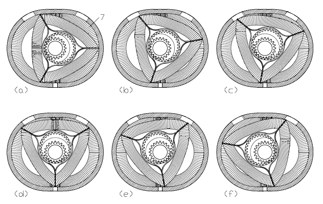
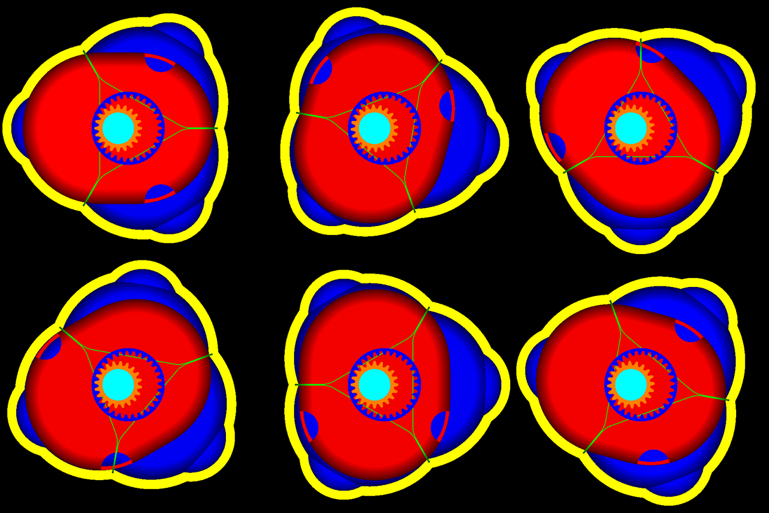
In the following PatWankel, wherein each seal and each groove serve one only working chamber, the working surface (whereon the seals abut and slide) is the external surface of the inner body:
Here is the inner body alone, with the three seals on it:
In the following drawing the two, of the three, seals have been removed.
The working chamber at left is at its TDC with its seal surrounding it and sealing it.
The inner body is like a "piston" pushed deaply into the working chamber (an unconventional piston that needs neither a connecting rod, nor a crankshaft).
At operation the "piston" (i.e. the inner body), remaining permanently in contact with the seal, is pushed outwards from the chamber and the volume increases, then the "piston" is pushed inwards and the volume decreases, and so on:
Every point of the inner periphery of the seal remains permanently in contact with the external surface of the inner body.
And if, instead of keeping the outer body (and the seals with it) immovable, the outer body is spinning at constant speed about a fixed axis (and the inner body with the working surface is also spinning at constant speed about another fixed axis), the elimination of the eccentric shaft comes with many other advantages:
Regarding the Wankel rotary engine:
Here is one of the worst problems the engineers of NSU and Mazda experienced several decades ago:
Confused?
No it is not the speed bumps on the roads.
It is the “speed bump” on the apex “road”, i.e. on the casing:
Look at the “speed bump” at the lower and at the top side of the casing.
Look at the “reverse” centrifugal force an apex seal experiences each time it passes from the area between the two spark plugs (or from the anti-diametrically from the spark plugs are).
Did you ever pass over a “speed bump” with, say, 50mph (80Km/h)?
Did the car take off the road?
Imagine an apex seal taking-off the casing (at the “speed bump” area) and landing later, several degrees of eccentric shaft rotation, on the casing, bouncing a few times . If an RX-8 is forced to over-rev (say, braking abruptly with the engine) it cannot avoid such a problem.
The Wankel RX-8 requires strong springs under the apex seals, otherwise each apex seal will take off the epitrochoid twice per revolution around the casing.
Think the difference in the PatWankel wherein the inner body rotates at constant seed about a fixed axis and the outer body rotates at constant speed about is own fixed axis, which means constant amplitude of the centrifugal acceleration.
Thanks
Manolis Pattakos
Advertisement
#20
Posted 05 February 2017 - 23:15
The PatWankel and the solutions you have produced to the many problems it presents are quite ingenious Manolis.
I must say however, that seal looks like a nightmare to me. Have you thought about how many pieces would comprise each seal and what the design of those joints would look like? http://www.competiti.../images/43Z.gif
#21
Posted 06 February 2017 - 05:10
You write:
“The PatWankel and the solutions you have produced to the many problems it presents are quite ingenious Manolis.
I must say however, that seal looks like a nightmare to me. Have you thought about how many pieces would comprise each seal and what the design of those joints would look like? http://www.competiti...images/43Z.gif”
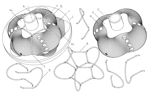
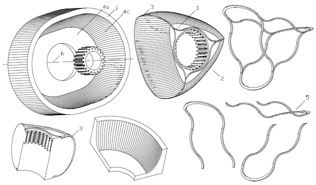
Each seal comprises one only piece and surrounds completely one working chamber. Just like in the reciprocating piston engines.
The ends of each seal of the PatRoVa can be like:
but not necessarily: only few reciprocating piston engines use gap-less piston rings (it seems their advantages are questionable).
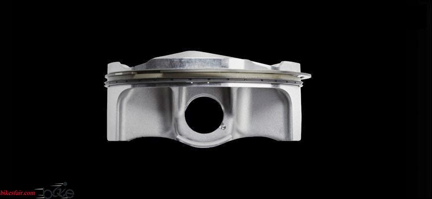
In the most expensive motorcycle of the world (Panigale Superleggera):
the piston has a single compression ring and it seems it is not gap-less.
Making the seals for a prototype PatWankel engine:
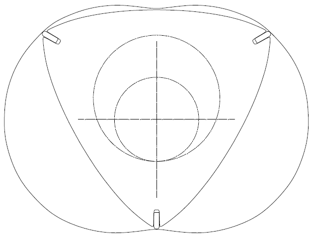
From a sheet (say, from a steel sheet having 1.5mm width) with a wire EDM machine the seal is cut accurately, say, as it appears at bottom – middle in this drawing (it resembles to a NR750 piston ring with the difference that here the working surface of the “ring” is its inner surface):
Then the seal is slightly bend to fit in its groove on the external body (as shown at bottom left and bottom right, radius R2). The radius R1 remains unaffected by this smooth bending.
With a nitride surface hardening the dimensions remain unchanged and the seal is ready to be used.
The seal needs a cut / gap somewhere, say as shown here (bottom middle):
Important: the R1 surface does not result from the bending of a metal strip. It comes from the accurate cutting, with a wire EDM machine, of a steel sheet.
In order to avoid the small change of the dimensions of the seal during the bending, the bending can be done before the EDM cutting: there are multi-axis wire EDM machines by which you can cut accurately an already bent sheet of metal.
Even for the first prototype, the manufacturing of a decent set of seals seems simple / cheap.
Quiz for the rest forum members (not Gruntguru):
Here is the kinematic mechanism of a Wankel rotary:
Here is the kinematic mechanism of a LiquidPiston:
Here is the PatWankel:
(the ports in the last two are for Atkinson-Miller cycle).
What is the difference in the loading of the synchronizing gearwheels in the three arrangements?
In which arrangement the combustion causes the heavy loading of the teeth of the gear-wheels?
What happens when the permanently (and heavily loaded) teeth start wearing?
If the combustion force is F, what is the force F’ on the teeth and what is the force F’’ on the eccentric bearing?
In which arrangement the combustion force “tuns” directly into toque on the “power shaft”?
How efficient do you think is to pass a heavy combustion force from body to body (by means of big diameter bearings) before it “turns” to torque on a power shaft?
Thanks
Manolis Pattakos
Edited by manolis, 06 February 2017 - 05:19.