Hello Pierrre.
You write:
"how long did it take you to learn those cad drawings and anmation?"
Does it matter?
CAD is a tool, like a lathe or like a 3D-Printer.
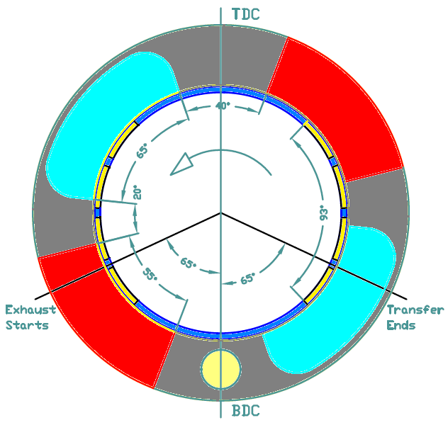
More useful is to describe how a specific animation (say, the last animation in this page, at post# 13) was made.
A reader of the discussion may learn one thing or two.
At https://www.pattakon...atATE_Piere.dxf is the AutoCAD 2000 drawing (in dxf format) whereon the animation is based.
And here is the AutoLisp program made to create automatically the 40 slides of the animation of my last post:
;**********************
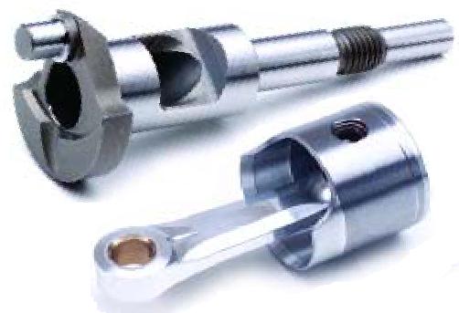
;you have ready the blocks: valve4 (sleeve valve), casing5 (casing), crankshaft4 ;(crankshaft), conrod (connecting rod) and piston (piston)
;before running the program, you open once the commands: rotate3d, insert (giving the ;right parameters) and render (giving also the basic parameters, like render to file and dimensions of the file).
;it is good to give at “Tools /Options” a higher (say 5) render smoothness.
;you also need to create a folder (c:/tempacad/) wherein the slide files will be stored.
;**********************
(defun c:anim (/ ste f r i d dd xx yy n)
(command "_.osnap" "" none "")
(setq r 25.0)
(setq f 0.0)
(setq ste 9.0)
(setq d 90.0)
(setq n 0.0)
(while (< f 360.0)
(command "_.erase" "all" "")
(command "_.insert" "valve4" (list 0.0 0.0) "" "" (/ f 1.0) "")
(command "_.rotate3d" "all" "" (list 0.0 0.0) (list 100.0 0.0) 90.0 "")
(command "_.insert" "casing5" (list 0.0 0.0) "" "" 0.0 "")
(command "_.insert" "crankshaft4" (list 0.0 0.0) "" "" f "")
(setq i (* (/ (+ f 180.0) -180.0) pi))
(setq xx (* r (sin i)))
(setq yy (* r (cos i)))
(setq dd (sqrt (- (* d d) (* xx xx))))
(command "_.insert" "conrod" (list xx yy) "" "" (* (/ 180.0 pi) (atan (/ xx dd))) "")
(command "_.insert" "piston" (list 0.0 (+ yy dd)) "" "" 0.0 "")
(setq n (+ n 1.0))
(if (= n 1.0) (c:render "c:/tempacad/1" () () ""))
(if (= n 2.0) (c:render "c:/tempacad/2" () () ""))
(if (= n 3.0) (c:render "c:/tempacad/3" () () ""))
(if (= n 4.0) (c:render "c:/tempacad/4" () () ""))
(if (= n 5.0) (c:render "c:/tempacad/5" () () ""))
(if (= n 6.0) (c:render "c:/tempacad/6" () () ""))
(if (= n 7.0) (c:render "c:/tempacad/7" () () ""))
(if (= n 8.0) (c:render "c:/tempacad/8" () () ""))
(if (= n 9.0) (c:render "c:/tempacad/9" () () ""))
(if (= n 10.0) (c:render "c:/tempacad/10" () () ""))
(if (= n 11.0) (c:render "c:/tempacad/11" () () ""))
(if (= n 12.0) (c:render "c:/tempacad/12" () () ""))
(if (= n 13.0) (c:render "c:/tempacad/13" () () ""))
(if (= n 14.0) (c:render "c:/tempacad/14" () () ""))
(if (= n 15.0) (c:render "c:/tempacad/15" () () ""))
(if (= n 16.0) (c:render "c:/tempacad/16" () () ""))
(if (= n 17.0) (c:render "c:/tempacad/17" () () ""))
(if (= n 18.0) (c:render "c:/tempacad/18" () () ""))
(if (= n 19.0) (c:render "c:/tempacad/19" () () ""))
(if (= n 20.0) (c:render "c:/tempacad/20" () () ""))
(if (= n 21.0) (c:render "c:/tempacad/21" () () ""))
(if (= n 22.0) (c:render "c:/tempacad/22" () () ""))
(if (= n 23.0) (c:render "c:/tempacad/23" () () ""))
(if (= n 24.0) (c:render "c:/tempacad/24" () () ""))
(if (= n 25.0) (c:render "c:/tempacad/25" () () ""))
(if (= n 26.0) (c:render "c:/tempacad/26" () () ""))
(if (= n 27.0) (c:render "c:/tempacad/27" () () ""))
(if (= n 28.0) (c:render "c:/tempacad/28" () () ""))
(if (= n 29.0) (c:render "c:/tempacad/29" () () ""))
(if (= n 30.0) (c:render "c:/tempacad/30" () () ""))
(if (= n 31.0) (c:render "c:/tempacad/31" () () ""))
(if (= n 32.0) (c:render "c:/tempacad/32" () () ""))
(if (= n 33.0) (c:render "c:/tempacad/33" () () ""))
(if (= n 34.0) (c:render "c:/tempacad/34" () () ""))
(if (= n 35.0) (c:render "c:/tempacad/35" () () ""))
(if (= n 36.0) (c:render "c:/tempacad/36" () () ""))
(if (= n 37.0) (c:render "c:/tempacad/37" () () ""))
(if (= n 38.0) (c:render "c:/tempacad/38" () () ""))
(if (= n 39.0) (c:render "c:/tempacad/39" () () ""))
(if (= n 40.0) (c:render "c:/tempacad/40" () () ""))
(setq f (+ f ste))
)
)
The bold letters show the five different commands the above AutoLisp program uses.
After opening the CAD drawing, the AutoLisp editor opens and the above AutoLisp program is loaded.
Giving the command “anim” they are created the 40 slides of the animation (it takes 2 minutes or so).
The time consuming work is to make (and correct / refine) the basic drawing, and then to make the AutoLisp program (which is nothing but how the parts relate with each other and where they go as the crankshaft turns).
Finally the 40 “bmp” files (created by the AutoCAD) turn to GIF files, and these files are combined using the old Microsoft GIF Animator to the animated drawing you see.
If there are questions, please do not hesitate to ask.
Thanks
Manolis Pattakos
Edited by manolis, 15 May 2020 - 05:31.


