Hello all.
PatEf
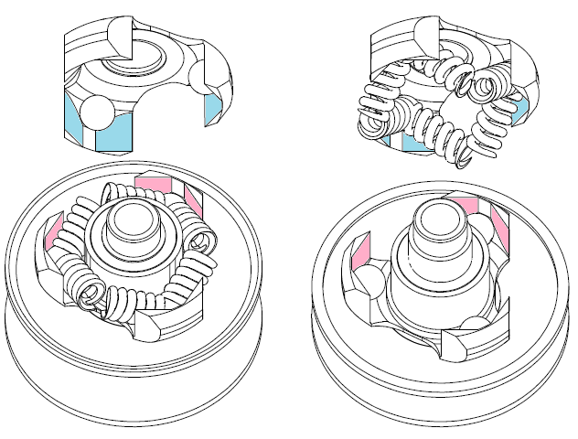
In Fig. 1 a V-belt CVT is shown at a short transmission ratio (drive shaft: 1, drive pulley: 2, driven shaft: 3, driven pulley: 4, V-belt: 5).
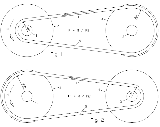
The torque M provided by the drive shaft 1 loads the V-belt by a force F=M/R2, wherein R2 is the radius at which the V-belt runs on the drive pulley 2.
In order to avoid "belt slippage" in the drive pulley, a minimum clamping of the V-belt between the two conical halves of the drive pulley 2 is required.
The same for the rear pulley: a minimum clamping is required, otherwise the pulley cannot apply the required force on the V-belt.
In Fig. 2 the transmission ratio (defined as the ratio of the angular velocity of the driven pulley 4 to the angular velocity of the drive pulley 2) is long, about double than in Fig. 1.
With the same torque M provided by the drive shaft 1, the substantially bigger radius R2' the V-belt runs on the drive pulley 2 reduces substantially the force F' loading the V-belt (F'/F=R2/R2') and proportionally the required clamping of the belt between the two conical halves of the drive pulley 2, and similarly it reduces proportionally the required clamping of the V-belt between the two conical halves of the driven pulley 4.
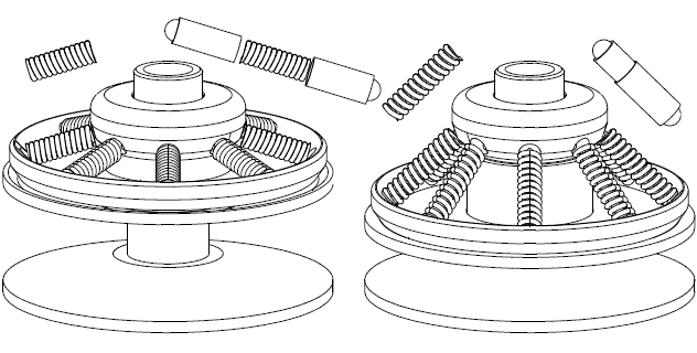
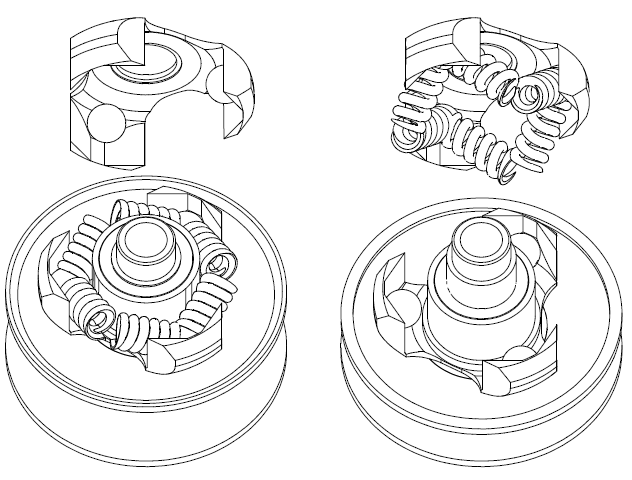
However, as shown in the following drawing, the driven pulley spring of a conventional CVT is heavily over-compressed at the longer transmission ratios.
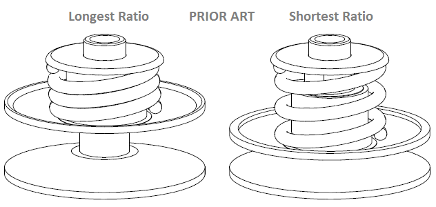
While the efficiency (i.e. the ratio of the output power to the input power) of a conventional V-belt CVT peaks, at the shorter transmission ratios and the heavier loads, even above 95%, the efficiency drops well below 85% at the longer transmission ratios (overdrive) and the lighter loads.
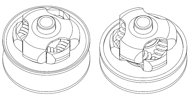
The low efficiency of the conventional V-belt CVT at the long transmission ratios comes from its architecture according which: a variator (or governor) at the drive pulley pushes its two halves close to each other, while a spring in the driven pulley is resisting and is forcing the two halves of the drive pulley away from each other.
And here is the principle according which the PatEf operates:
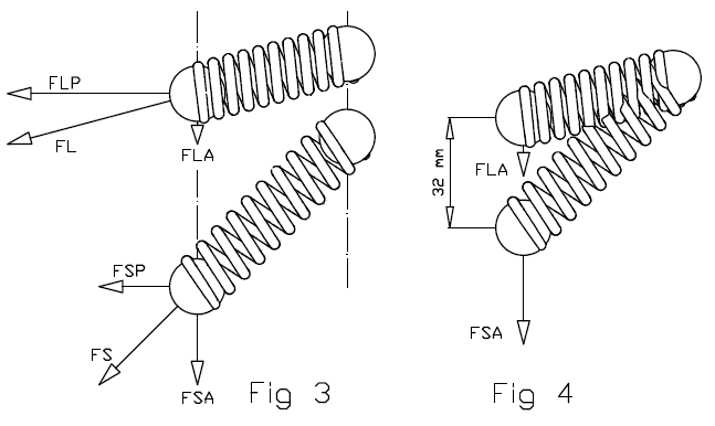
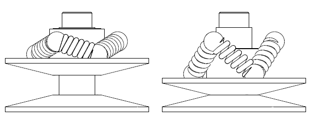
In Fig. 3 as the spring is more compressed, the force (FS, FL) it applies along its direction increases: FL>FS (the L stands for longer ratios, the S stands for shorter ratios).
Analyzing the total force FL in an axial component force FLA parallel to the rotation axis 3A of the driven shaft 3 (the A in the FLA stands for axial) and in a perpendicular component force FLP on a plane perpendicular to the rotations axis 3A (the P in the FLP stands for perpendicular), and similarly for the FS which is analyzed in an axial component force FSA (parallel to the rotation axis 3A) and in a perpendicular component force FSP (on a plane perpendicular (normal) to the rotation axis 3A), despite the increase of the total force the spring applies at the longer ratios (because it is further compressed), the axial component of the force can reduce substantially at the longer transmission ratios (and proportionally can reduce the clamping of the V-belt), as the following plot shows:
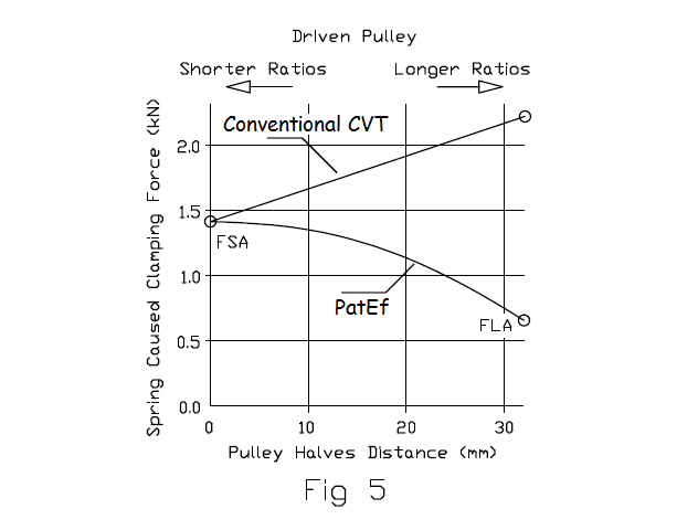
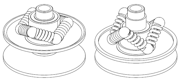
The arrangement of the springs is such that, while for higher and higher transmission ratios the springs are more and more compressed (providing a stronger and stronger force), the axial forces the springs apply on the two halves of the driven pulley (and the clamping of the V-belt these forces cause) is reduced.
The above plot shows the "spring caused clamping" versus the distance between the two halves of the driven pulley for a conventional CVT and for a CVT having the PatEf (to be noted: at 0mm distance, the two halves are at the closest to each other position, which means the V-belt is running at the maximum diameter in the driven pulley).
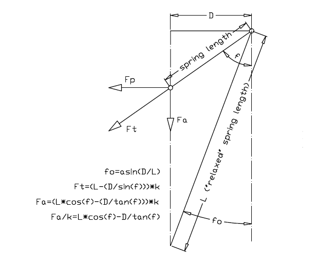
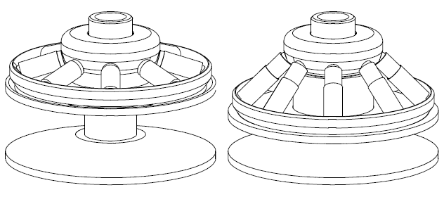
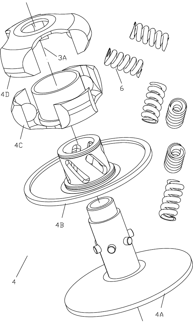
The above drawing shows the arrangement of a spring (actually of the axis of a spring) of the PatEf.
The relaxed length of the spring (i.e. the length of the spring when it is unloaded) is L, and its projection on a horizontal axis has constant length D due to its arrangement.
The axis of the spring has an inclination f relative to the rotation axis of the driven pulley (the rotation axis of the driven pulley is not shown, but it is parallel to the dashed-dot lines of Fig 31).
The total force provided by the spring is Ft along the spring "axis", with:
Ft=(L-(D/sin(f)))*k, wherein k is the stiffness of the spring.
The axial component of the Ft is Fa, with:
Fa=(L*cos(f)-(D/tan(f)))*k
In the following plot it is shown the resulting axial force versus the spring inclination angle of the arrangement in the above drawing, for springs having various lengths.
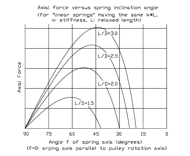
For the specific plot (but not obligatory) the stiffness k of each spring is taken reverse proportional to its length, which means constant k*L (to make springs of constant k*L one could use the same wire, the same coil diameter and the same pitch).
Following the curve "L/D=2.5", one can see that the resulting axial force is zero until f=23.5 degrees (relaxed spring, asin(1/2.5)=23.5 degrees). Then the spring is progressively compressed.
Until f=48 degrees the axial force increases with the compression of the spring (but not linearly).
After the 48 degrees (at which the curve "L/D=2.5" maximizes), while the further increase of the angle f of the spring axis causes the further compression of the spring (because its effective length reduces), the resulting axial force reduces.
From 60 to 90 degrees (at 90 degrees the resulting axial force gets zero) the drop of the axial force varies, more or less, linearly with the angle f.
For instance, designing the driven pulley and its springs so that at the shortest transmission ratio (i.e. completely closed driven pulley and V-belt runsing at the maximum diameter on the driven pulley) the spring inclination to be f=53 degrees, and at the longest transmission ratio (i.e. completely open driven pulley and V-belt running at the minimum diameter on the driven pulley) the spring inclination to be f=75 degrees ("Axail force vs Spring inclination angle" plot), the resulting axial force (and the clamping it causes on the V-belt) reduces progressively and substantially as the transmission ratio increases.
The resulting axial force (and the clamping it causes) at the longest transmission ratio is nearly 50% of what it is at the shortest transmission ratio.
The 50% reduction of the clamping force at the longest transmission ratio fits well with what the Figs. 1 and 2 show.
Practically:
If the driven pulley of a scooter CVT is modified to PatEf, the ramps and the roller weights of the variator have also to be modified to fit with the substantially different clamping of the V-belt along the operating range.
After the modification, the scooter (or vehicle in general):
will be greener / more fuel efficient (a part of the fuel previously burnt to provide energy consumed in the CVT as friction, is saved),
the scooter will have higher top speed,
the CVT will run substantially colder and will need less energy for cooling / ventilation,
the V-belt will last far longer (because it avoids running under extreme over-clamping).
The mechanism fits also with bicycles having a V-belt CVT for the transmission from the pedals to the rear wheel (as in the GB 2,526,675 patent (PatBox CVT), for instance).
The reduction of the over-clamping (and of the associated friction loss) is more significant in a bicycle because of the small available human power.
The simplicity is among the characteristics of the PatEf.
The saving of fuel and of power are also characteristics of the PatEf.
The "automatic operation" is also a characteristic of the PatEf: after the assembly of the driven pulley, the reduction of the clamping force is realized automatically without external parts or control systems.
According the previous:
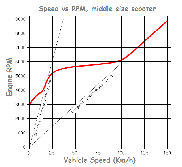
With the PatEf the mileage of a conventional middle size scooter can be improved more than 10% at typical highway cruising (say, 100Km/h (62mph) wherein the engine runs at medium load and wherein, according the above plot, the CVT runs already at (or near) its longest transmission ratio, which means the V-belt, in case without the PatEf, runs under extreme over-clamping (see the "efficiency vs over-clamping" plot, third image from top in this web page).
With some three times lighter V-belt clamping, the expected durability of the V-belt gets several times longer.
With the PatEf the scooter can also accelerate faster because a part of the energy previously consumed on the V-belt and on the pulleys, now accelerates the scooter, reducing at the same time the V-belt wear.
With the PatEf the scooter can also achieve a higher top speed. Because at the maximum speed the CVT cannot help running at its longest transmission ratio wherein the over-clamping of the V-belt consumes (in friction and belt wear) a part of the power provided by the engine; with the PatEf, this power part is utilized: it is pushing the scooter / sled / ATV / car / bicycle forwards, improving at the same time the durability of the V-belt .
Thoughts ?
Thanks
Manolis Pattakos