Jump to content


Photo
- - - - -

HCCI controllable combustion / PatBam


  • Please log in to reply
68 replies to this topic

#1 manolis

manolis
  • Member

  • 935 posts
  • Joined: May 03

Posted 25 November 2017 - 14:53

Hello all.
 
HCCI controllable combustion
 
For 2-stroke and 4-stroke engines.
 
Prior Art:
 
PatBam_1.png
 
PatBam_2.png
 
Prior art (Nautilus Engineering):
 
Nautilus_Engineering_Piston_Rod.png
 
 
PatBam_12.png
 
A look at the above plot / example is indicative for the problems of the prior art. 
 
Starting the compression stroke with 1 bar pressure, at 33 degrees before the TDC / 12 bar in the united combustion chamber, the auxiliary combustion chamber is sealed and its pressure rises at 33 bar (wherein the threshold for auto-ignition is) some 14 degrees before the TDC (corresponding to about 2% of the piston stroke). 
 
Then the air-fuel mixture inside the auxiliary combustion chamber auto-ignites and its pressure at the TDC is way higher than the 48 bar of the case without ignition. 
 
The pressure of the air-fuel mixture in the main combustion chamber never exceeds the 29 bar, i.e. it is below the threshold for auto-ignition. 
 
So, after the TDC the air-fuel mixture in the main combustion chamber expands not-yet-burnt until 33 degrees after the TDC, when the two combustion chambers unite into one, with the burnt gas from the auxiliary combustion chamber igniting the not-yet burnt mixture. 


PatBam
 
With the PatBam things are similar until the auto-ignition of the air-fuel mixture inside the auxiliary combustion chamber. 
 
Then, a little after the auto-ignition in the auxiliary combustion chamber, the auxiliary piston passes over the passageways formed on the inner side of the auxiliary cylinder, allowing the hot (and at high pressure and full of active radicals) burnt gas to enter into the main combustion chamber and ignite it, exploiting all the 11:1 expansion ratio and achieving a high thermal efficiency.
 
PatBam_3.png
 
PatBam_4.png
 
PatBam_5.png
 
PatBam_6.png
 
PatBam_7.png
 
PatBam_8.png
 
PatBam_9.png
 
PatBam_10.png
 
PatBam_11.png
 
 
PatBam_Anim.gif


Thoughts?
 
Objections?
 
Thanks
Manolis Pattakos

Edited by manolis, 25 November 2017 - 15:52.


Advertisement

#2 gruntguru

gruntguru
  • Member

  • 7,642 posts
  • Joined: January 09

Posted 27 November 2017 - 02:46

Some nice ideas as usual Manolis.

I question the concept of "pre-chamber HCCI" in general. The benefit of HCCI is near-simultaneous ignition of the entire charge near TDC. In this system, only the pre-chamber operates a HCCI cycle while the other 99% is ignited in a manner similar to "jet ignition".


There is a better way to operate an engine with jet ignition. Just use the Mahle TJI or similar and get rapid combustion plus full control over ignition timing and AFR.


#3 manolis

manolis
  • Member

  • 935 posts
  • Joined: May 03

Posted 27 November 2017 - 06:59

Thank you Gruntguru.


Here is the Mahle TJI :


Mahle_TJI.jpg


and here is 1st page of their recent US patent:


Mahle_TJI_US_patent.png


You write:

The benefit of HCCI is near-simultaneous ignition of the entire charge near TDC. In this system, only the pre-chamber operates a HCCI cycle while the other 99% is ignited in a manner similar to "jet ignition.

There is a better way to operate an engine with jet ignition. Just use the Mahle TJI or similar and get rapid combustion plus full control over ignition timing and AFR.”


Here are some characteristics that distinguish the two systems from each-other, the Mahle TJI and the PatBam.


1.

The Mahle TJI requires a high pressure / high tech injector to directly inject a small quantity of fuel into the pre-camber.


The PatBam needs not direct injection. Not even an injection system. Even with a carburettor it would work, because it’s ignition is tolerant to the air-fuel ratio in a wide range.

Think of it as an add-on, that replaces the spark plugs of old carburetted engines and how much the emission would drop.


This makes the PatBam cheaper and simpler.


2.

The Mahle TJI requires a high voltage ignition system to put fire onto the “rich” air-fuel mixture in the pre-chamber.


The PatBam needs not a high voltage system, nor spark plugs. The high compression inside the pre-chamber causes the auto-ignition of the lean mixture therein (HCCI).


This makes the PatBam not only cheaper and simpler but also more reliable (think of an airplane engine wherein they use now two independent ignition systems and two spark plugs per cylinder, for safety).


3.

In the Mahle TJI pre-chamber, the combustion takes place at low pressure with the pre-chamber communicating permanently with the main chamber.

The spark plug ignites the rich mixture in the pre-chamber, and as the flame expands, it pushes a good part of the still un-burnt mixture from the pre-chamber, through the permanently open ports (orifices), into the compressed lean air-fuel mixture in the main chamber.

It seems as only a small part of the mixture in the pre-chamber will be really burnt therein and then it will pass – as burnt gas - into the main chamber (in their patent they repeat the word “proximal” to characterise the position of the spark plug and the pre-chamber injector). So, the size of the “auxiliary chamber” of the PatBam animation seems big; more likely, it will be a little bigger than the idle valves used in the VVA-roller Honda Civic Vtec B16A2 protoype:


VVA_Idle_Valves.jpg


(the bronze items, more at http://www.pattakon....onIdleValve.htm )


Worse even, it seems the pressure in the TJI pre-chamber cannot get too high to push the burnt gas “explosively” into the main combustion chamber.

It is more like a fire-gun:


2021932237.png    


Mahle_TJI_ign.jpg


In the PatBam a little after the auto-ignition of the lean mixture inside the pre-chamber, the ports / orifices open.

The high pressure difference between the pre-chamber and the main chamber causes an explosive discharge / penetration of the burnt gas from the pre-chamber into the compressed air-fuel mixture in the main chamber (in a way similar to the direct injection Diesels wherein the penetration of the fuel is achieved with some 2,000 bar injection pressure for liquid injection).

The active radicals penetrate “instantly” (in comparison to Mahle’s TJI) in the compressed air-fuel mixture, which also undergoes a pressure sock.

All these trigger the HCCI combustion of the rest mixture.


I.e. in the one case (Mahle TJI) burnt gas if blown into the compressed air-fuel mixture in the main combustion chamber providing a faster and more stable combustion of the lean mixture, while in the other case (PatBam) the conditions favour true HCCI combustion not only in the pre-chamber, but into the main chamber as well.


4.

Again the penetration issue.


Having some 10 times higher density than the induction density, and having such swirl and turbulence as in a modern combustion chambers, and having to inject not liquid but gas, the penetration is the critical characteristic for achieving true HCCI combustion across and through the main chamber.


Thanks

Manolis Pattakos


#4 PJGD

PJGD
  • Member

  • 143 posts
  • Joined: April 04

Posted 29 November 2017 - 01:58

Engines that have what are often (for obvious reasons) called "poker" pistons have been very common in the past in divided chamber diesel engines.  Typically, the poker is not a really close fit in the pre-chamber so it is not the same situation as is necessary to achieve two distinct pressures.  One reason that they did it in the old days when engines were very much less robust than they are today and fuel injection was less well controlled, was so that the initial pressure spike after the long ignition delay that they had back then acted on the small face area of the poker rather than the whole piston area, thus the mechanical loading on the engine scantlings was much reduced, the engine was quieter, and it lasted much longer in service.  This same logic applies today in the case of HCCI engines where a major development challenge has been to attenuate the near instantaneous combustion and high pressure rise rates.  This is why poker pistons such as the Nautilus attempt are making a comeback.


However, Nautilus seem to think that they have invented the concept, but it has been around for decades.  With the possible exception of their alternating inlet/exhaust valves, everything that they are claiming and more appears in the Chatterton patent GB1156821, while an even earlier example is in the Kammer patent GB509123 and I am sure there are others.  Chatterton gives a good explanation of how he expected it to work and he includes the truly key feature of VCR in the pre-chamber so that combustion is assured under all ambient temperatures and with any fuel.  And when it comes to VCR, this is about as simple as it gets.


To make this concept practical, and specifically to achieve and maintain the close fit of the poker in the prechamber, I think that a unit head (individual head per pot) that is located via a spigot on the liner and a steel piston (because of the closer piston-to-liner clearance that is possible) will be necessary.


Kammer_GB509123_Poker.pngChatterton_GB1156821_Poker.pngPielstick%20VG%20IDI%20Chamber.png


PJGD


#5 manolis

manolis
  • Member

  • 935 posts
  • Joined: May 03

Posted 29 November 2017 - 07:07

Thank you PJDG


The following plot is from Mahle’s US patent:


Mahle_TJI_US_patent_burn_angles.png


In a conventional gasoline engine it is required some 40 degrees spark advance, with:


10% of the mixture burnt more than 5 crankshaft degrees before the TDC,


50% of the mixture burnt before 6 degrees after the TDC,


and 90% of the mixture burnt before 20 degrees after the TDC;


on stoichiometric, from the spark to when the 90% of the mixture is burnt, it takes 50 degrees,


on lean mixture (lambda=1.4), the required spark advance is 52 degrees, and the 90% of the fuel needs some 80 crank degrees, counted from the spark, to get burnt).


In comparison, a similar engine equipped with Mahle’s TJI, needs substantially shorter spark advance and achieves faster combustion.


For instance, in the case of lean mixture with lambda=1.4, the 50% of the mixture is burnt into 26 crankshaft degrees after the spark in the Mahle TJI, while in the conventional it takes 60 crankshaft degrees.


On the other hand, the Mahle TJI introduces its own delays. The rich mixture inside the pre-chamber needs time from the spark to the ignition (i.e. to a noticeable pressure rise relative to the pure compression without spark).


With the PatBam, the combustion into the pre-chamber is – in comparison – instantaneous (compression / temperature above threshold, true HCCI).


PatBam_Anim_2.gif


The explosive way the burnt (or the still burning) gas gets into the main chamber (which was maintained slightly below the threshold), and the pressure sock can trigger an HCCI combustion (or at least a faster, in comparison with Mahle’sTJI, combustion) therein (theoretically, at least)


Besides the faster combustion, the simplicity is another characteristic of the PatBam as compared to the TJI.


In the animation above, a perfect sealing is not feasible, but may prove also not necessary.


With steel pistons and smaller clearances (of the order of 0.01mm), the simple structure of the above animation (which is rid of inertia loads) may prove adequate (the burnt gas penetrates deeper, having more active/alive radicals in it; and the communication between the main chamber and the pre-chamber (auxiliary chamber) happens a few degrees (say 10) before the TDC).


As for the prior are (Nautilus / Riley, Roberts, Kammer, Chatterton etc) the delay until the pre-chamber to start spreading the radicals into the main chamber is too late, giving the time to the radicals to die out).


PatBam_12.png


In addition, when the two chamber start communicating at the angle +f (~33 degrees after the TDC) the remaining expansion is only 5.5:1, while the thermal losses (during the compression) and the friction correspond to 11:1 compression ratio.


Thanks

Manolis Pattakos


#6 manolis

manolis
  • Member

  • 935 posts
  • Joined: May 03

Posted 30 November 2017 - 03:39

Hello PJGD


In the P-V plot at the end of the last post, besides the color it has been added one more curve, the green: it is for a compression ratio 5.5:1


Supposing that the two chambers (main chamber and pre-chamber) of the prior art (Chatterton, Roberts, Nautilus, etc) are sealed from each other for the last 10% of the piston stroke, supposing also a “con-rod to stroke” ratio equal to 2, the combustion in the main chamber starts 33 degrees after the TDC wherein the pressure (blue curve) has fallen at only 11bar (from the 29bar it was at the TDC).


With conventional operation (one united combustion chamber) and 2.2 times bigger dead volume, the compression ratio drops from 11:1 to 5.5:1, resulting in an 11bar pressure at the TDC (green curve).


For a fuel molecule burnt:

either at the TDC in the case of the united combustion chamber (green curve, CR 5.5:1),

or at 33 degrees after the TDC in the case of the divided combustion chamber (blue curve, CR 11:1 in the main chamber),

the indicated efficiency is the same (because the remaining expansion ratio is 1:5.5 in both cases).


However, the thermal and frictional losses are substantially increased in the case of the divided chamber (blue curve, 11:1 compression ratio in the main chamber) wherein the pressure rises at 29bar at the TDC, making the overall BTE lower than in the conventional running at half (5.5:1) compression ratio (and way lower than in a conventional running at 11:1 compression ratio).


One could claim that the substantially faster combustion in the case of the divided combustion chamber would cover the abovementioned increased thermal and frictional losses.


However, despite the faster combustion (due to the active radicals from the pre-chamber into the main chamber), the piston speed at 33 degrees after the TDC (blue curve) is 3 times faster than at 10 degrees after the TDC, which further reduces the actual expansion ratio, spoiling the BTE even more.


For instance, if the combustion completes into only 10 degrees after the two chambers unite into one, the average expansion ratio drops from 1:5.5 to 1:4.5 (according the plot, at 33+(10/2)=38 degrees after the TDC, the volume (orange curve) in the combustion chamber is 24, which means an expansion ratio of 24/110=1:4.5, wherein 110 is the cylinder capacity (100) plus the dead volume (10)).


It seems as the solution proposed by the prior art (Chatterton etc) creates other – worse – problems:


in order to increase the BTE, a faster combustion (or an HCCI combustion) was regarded as the most important,


and in order to achieve the faster combustion, the prior art (Chatterton etc) sacrifices the most important part of the piston stroke (the last 10%, or so, of the piston stroke,  which corresponds to ~70 degrees around the TDC); during this part of the piston stroke the air-fuel mixture in the main chamber undergoes a strong compression and expansion waiting the combustion to happen, adding significant thermal and frictional losses;

and when the “faster” combustion eventually happens, then it is too late because the remaining expansion ratio is too low for good BTE (Brake Thermal Efficiency).


Now take another look at the PatBam.


PatBam_3.png


The faster combustion (or the controllable HCCI combustion) and the capability of the engine to burnt extra lean mixtures, are again the tools for increased BTE.


But in the PatBam things happen without delay, allowing full expansion (1:11 expansion ratio in the example of the plot) and improved BTE.


Thanks

Manolis Pattakos


#7 Kelpiecross

Kelpiecross
  • Member

  • 1,730 posts
  • Joined: October 10

Posted 02 December 2017 - 06:08


Manolis - am I mistaken but in your PatBam engine does the main piston actually strikes the small auxiliary piston to operate the system? Surely collisions like this would be incredibly noisy and damaging?

#8 manolis

manolis
  • Member

  • 935 posts
  • Joined: May 03

Posted 02 December 2017 - 16:16

Hello Kelpiecross.


Here is another version wherein there are neither inertia loads not "impact" noise.


PatBam_PPE_Anim_2.gif


PatBam_PPE_Anim.gif


In theabove animations the PatBam is applied on a Pulling Piston Engine (PPE, for more click ); 
 

the lubrication in the crankcase is 4-stroke; 
 

the design is cross-head; 
 

the piston is not touching the bore (only the piston rings touch the bore and need lubrication; the piston itself does not need any lubrication); 
 

the dead volume of the "scavenging pump" can be variable and can be as small as desirable; 
 

the reed valve (without its petals) is shown inside the bellmouth (at top). 


The "piston rod" aligns precisely the auxiliary chamber (formed inside the piston) with the auxiliary piston (secured to the casing).


Thanks

Manolis Pattakos


#9 gruntguru

gruntguru
  • Member

  • 7,642 posts
  • Joined: January 09

Posted 04 December 2017 - 03:41

- Cold start aids?

- Idle, part load? Would it need EGR, charge heating etc to ignite reliably?

- Ignition timing vs rpm?


#10 manolis

manolis
  • Member

  • 935 posts
  • Joined: May 03

Posted 04 December 2017 - 09:12

Hello Gruntguru.


Cold start:


With an adequately high compression ratio in the auxiliary chamber, the cold start, theoretically, has no problem.

If necessary, a glow plug can help.


EGR:


The EGR is an option, but it needs extra complication / parts / control.


The objective is to burn lean and extra lean mixtures at the minimum complication.


If the compression in the auxiliary chamber is high enough to rise the temperature above the threshold for auto-ignition, the mixture, no matter how lean it is, will ignite as in a Diesel running at very low load (idling).


With reference to the last animation, the piston, like a hammer, hits the trapped into the auxiliary chamber air-fuel mixture against the “anvil”.


And right after the auto-ignition, just before the TDC, the auxiliary chamber evacuates explosively into the main chamber, wherein the lean mixture is at its highest compression.


This gives a better chance (relative to Mahle’s TJI) for faster  or HCCI combustion of even leaner mixtures in the main chamber.


The purpose is to burn in the main chamber right after the TDC.


A higher compression ratio with a combustion extending substantially after the TDC has a lower BTE than a smaller compression ratio with the combustion happening faster, just after the TDC.


Ignition timing vs rpm


Optimizing the capacity of the auxiliary chamber (in the last two animations it contains more than 1/5 of the charge), and opening it just before the TDC to burst explosively into the main chamber to trigger the combustion therein, it makes more sense that we can achieve HCCI combustion into the main chamber at lower compression ratios and for leaner mixtures.


If this is the case, then does the ignition timing vs rpm matter?


On the other hand, there is a version of the PatBam (that with the eccentric cam) that can provide control over the ignition of the air-fuel mixture into the main chamber.


If we add the “anvil” to the following 2-stroke 2-cylinder balanced PPE:


PPE_2Stroke_2Cylinder_Balanced.gif


and modify properly the piston crown, then we have a PatBam.


Thanks

Manolis Pattakos


#11 gruntguru

gruntguru
  • Member

  • 7,642 posts
  • Joined: January 09

Posted 04 December 2017 - 23:55

Hi Manolis.

It sounds like your intention is to control load with enleanment only? The comparison to an idling diesel is not valid unfortunately. Regardless of load, diesel ignition occurs at near stoichiometric conditions, this occurs near the surface of a sprayed fuel droplet. Ultra - lean homogeneous mixtures require extremely high temperatures to ignite - much higher than I would anticipate in the PatBam prechamber.


For unthrottled idle and light load operation the AFR would need to be many times (say 10x?) the full load AFR. Perhaps some combination of throttling and enleanment would work, but I think you would probably need EGR to give adequate, temperature, pressure and richness for reliable ignition. This will be particularly difficult during warm-up.


#12 manolis

manolis
  • Member

  • 935 posts
  • Joined: May 03

Posted 05 December 2017 - 07:37

Hello Gruntguru


You write:

“It sounds like your intention is to control load with enleanment only? “


It should be a better solution.

However the throttling (and the fueling) control, if required, can be as in the prior art.


You also write:

“The comparison to an idling diesel is not valid unfortunately. Regardless of load, diesel ignition occurs at near stoichiometric conditions, this occurs near the surface of a sprayed fuel droplet.”


You also write:

“Ultra - lean homogeneous mixtures require extremely high temperatures to ignite - much higher than I would anticipate in the PatBam prechamber.”


I think not.


The threshold temperature for auto-ignition is the same, no matter how lean the mixture is.


Even with one only molecule of fuel into the pre-chamber and a, say, compression ratio of 20:1 therein, the temperature of the compressed air gets substantially above the threshold for auto-ignition.

The molecule of the fuel colliding with its neighbouring oxygen atoms has little reason to not get burnt.


A fuel molecule doesn’t “know”, at least at the beginning of the ignition, how close another fuel molecule is.


For comparison, in the giant marine Diesels a 12:1, or even lower, compression ratio is common place, which means that with 12:1 compression ratio the temperature of the air goes well above the threshold for the ignition of the diesel fuel droplets, even at cold start.

The threshold temperature for the auto-ignition of the gasoline fuel is higher than of the Diesel fuel; however the compression in the pre-chamber is higher, too, which rises substantially the temperature of the air at the end of the compression.


While the volume to surface ratio is many times higher in the giant Diesels than in the normal size Diesels, the Skyactiv-D Diesel of Mazda runs at only 14:1 compression ratio and claims top BTE.


At a first approach, supposing adiabatic compression and 20:1 compression ratio, the pressure of the air would rise at 20^1.4=66bar.

Applying this pressure rise to the P*V=n*R*T gas law, the absolute temperature will rise for 66/20=3.3 times (say, from 300 degrees Kelvin to ~1000K (~700 degrees Celsius).


The thermal loss towards the surrounding walls reduces this final temperature, however, taking into account that the ignition temperature of the gasoline is less than 300 degrees Celsius, it would be difficult to achieve misfire in the pre-chamber.  


We have no data / facts yet for the previous.


However we have some other data:


When we measured repeatedly the idling consumption of the VVA roller Honda Civic VTEC B16A2 prototype (more at http://www.pattakon....onIdleValve.htm ) we found it as 1lit per 3 hours at 330 rpm.


img004.png


With 1600cc engine capacity, the above fuel consumption and rpm say that the engine was running at 5.5 times lower, than full, load.


Feeding the PatBam with 5.5 times leaner than stoichiometric mixture, the compression in the pre-chamber (auxiliary chamber) is high enough to cause the auto-ignition (HCCI) of the lean mixture therein.


Because it seems that what matters for the auto-ignition is whether the temperature of the air-fuel mixture is above the threshold.

And this is not affected by the extra high lambda (air to fuel ratio): when the temperature rises enough, the molecules of the fuel will react with their neighbouring oxygen atoms and burn.


The question is whether the compressed (and similarly lean) air-fuel mixture in the main chamber will ignite when the auto-ignited lean mixture from the auxiliary chamber will meet the unburnt compressed gas in the main chamber exactly at the TDC wherein the conditions for ignition are the best, by far.


If the compression ratio in the main chamber is near the threshold, it will.


The bigger the capacity of the auxiliary chamber relative to the cylinder capacity, the better.


In comparison, in the prior art the conditions existing at the crank angle at which the two chambers start communicating with each other are by far worse than they where at the the TDC (the pressure and the temperature are substantially lower, the penetration of the burnt gas into the unburnt gas is questionable).


You also write:

“For unthrottled idle and light load operation the AFR would need to be many times (say 10x?) the full load AFR. Perhaps some combination of throttling and enleanment would work, but I think you would probably need EGR to give adequate, temperature, pressure and richness for reliable ignition. This will be particularly difficult during warm-up.


This is the challenge.


And a solution seems to be the hammering of the lean fuel trapped into the auxiliary chamber onto the “anvil” as hard as required to auto-ignite.


The height of “transfer ports” of the auxiliary chamber (or pre-chamber) defines how hard the hammering of the fuel onto the anvil will be.


PatBam_Anvil_High.gif


Different height of “transfer ports” give different auxiliary chamber compression ratio; higher in the above animation, lower in the animation below:


PatBam_Anvil_Low.gif


If necessary, this height can be variable.


Thanks

Manolis Pattakos


#13 gruntguru

gruntguru
  • Member

  • 7,642 posts
  • Joined: January 09

Posted 06 December 2017 - 05:41

Hi Manolis. I can't fault your logic regarding auto-ignition. Also interested to learn that idle load X 5.5 = full load. My 10x guess was way out.


You have assumed stoichiometric mixture at full load. I would imagine that a cheap small-engine version would operate at lambda 0.9 for power whilst a high efficiency, low emissions version would operate at 1.4 or more (to maintain peak efficiency and avoid the NOx peak). This engine would then run at 1.4 x 5.5 = 7.7 at idle if naturally aspirated and much leaner in the more likely case of being turbocharged. These mixtures (even 5.5) would not support flame propagation so the main chamber would need to be heated to the auto-ignition temperature when the transfer port opens. I think this is unlikely.


Edited by gruntguru, 06 December 2017 - 05:42.


#14 manolis

manolis
  • Member

  • 935 posts
  • Joined: May 03

Posted 06 December 2017 - 15:56

Hello Gruntguru.


You write:

This engine would then run at 1.4 x 5.5 = 7.7 at idle if naturally aspirated and much leaner in the more likely case of being turbocharged.”


At idling, the turbocharger cannot provide any increase of the inlet pressure.


You also write:

These mixtures (even 5.5) would not support flame propagation so the main chamber would need to be heated to the auto-ignition temperature when the transfer port opens. I think this is unlikely.


In this video:


Mazda presents their SkyActiv-X technology.


The compression ratio is 20:1.


The SkyActiv-X “generates a fireball with spark plug” that triggers the HCCI combustion in the cylinder (rapid and simultaneous combustion at multi points).


With extra lean mixture, the creation of a fireball means the propagation of the flame at some distance from the initial spark. It is not clear whether Mazda uses some kind of stratified charge to keep richer the mixture near the spark plug.


In the PatBam the principle is different.


Millions of active radicals (being generated into the auxiliary chamber) spread into the compressed mixture in the main chamber, just before the TDC, each acting as a spark.


While the ignition is not stable (due to the extra lean or lean mixture), from the millions of ignitions some will propagate a little, increasing the pressure and temperature into the cylinder and causing the auto-ignition of the compressed mixture.


For instance, if for every 1,000 radicals the 999 put out and only the one causes a tiny “fireball” of, say, 0.1mm diameter, the temperature increase will cause the HCCI combustion of the mixture in between neighboring “fireballs” (theoretically).


I.e. the PatBam does not rely on a flame development / propagation mechanism at all.


The 20:1 compression ratio of the Mazda SkyActiv-X may be right for the control over the HCCI, but it adds friction and heat losses due to the excessive temperature and pressure, and due to the attenuated combustion chamber.


The breathing is another issue.

With 20:1 compression ratio, a large/wide valve overlap is not easy.


Another issue is the robustness of the engine parts.

The pistons, the connecting rods, the bearings, the crankshaft and the casing of the gasoline HCCI SkyActiv-X of Mazda have to be stronger (and so, heavier) than those of the Mazda SkyActiv-D Diesel (which has only 14:1 compression ratio) due to the substantially heavier loads they bear.


The revving is another issue.

While 4,000 rpm is regarded as high revving for a Diesel, for the gasoline HCCI the 6,000+ rpm is “mandatory”.

With 6,000 rpm and heavier moving parts, the inertia loads (and the vibrations) increase more than two times.


20:1 compression ratio is, theoretically, better than 11:1.


However, the same deviation from the “constant volume combustion” has a much worse effect on the 20:1 compression ratio than on the 11:1, not to mention the substantially higher thermal and mechanical losses of the 20:1 compression ratio engine.


Last, but not least, is the added cost to the engine: the gasoline SkyActiv-X will be more expensive than a similar Diesel.


It seems that in order to solve the problem of the control over the HCCI combustion, Mazda introduced several new problems / side effects.


With the PatBam the idea is to keep the compression ratio of the main chamber considerably under the 20:1 of Mazda, without compromising on the thermal efficiency and on the specific power.


In the PatBam the first step is to auto-ignite the homogeneous mixture into the auxiliary chamber by increasing the pressure as much as necessary; the second step is to pass (the arrows) this still burning and highly active gas through the transfer ports:


PatBam_14.png


at as high speed as necessary to penetrate into the main chamber as deeply as required.  


Thanks

Manolis Pattakos  


#15 gruntguru

gruntguru
  • Member

  • 7,642 posts
  • Joined: January 09

Posted 06 December 2017 - 21:55

My bad on the turbocharged mixture range - thanks.


Not sure the gas passing through the transfer ports will be still burning, having undergone HCCI (very rapid) combustion Also not sure of the chemical reactivity of these gases since the pre=chamber mixture is lean/ultra lean.


"Fireballs" require flame propagation to form. Flame propagation does not occur beyond some lean limit. Consider the TJI system. A jet of radicals produced by the combustion of a rich mixture in the pre-chamber, contacts large regions of the main chamber in a very short space of time. Combustion is very rapid and temperatures and pressures rise very quickly but HCCI does not occur and reliable combustion only extends to about lambda 2.2


Is the SkyActive engine turbocharged? If not, its compression pressure may be less than the highly turbocharged diesel with 14:1 CR.


#16 manolis

manolis
  • Member

  • 935 posts
  • Joined: May 03

Posted 07 December 2017 - 13:50

Gruntguru, thanks for your thoughts / objections.


You write:


“Not sure the gas passing through the transfer ports will be still burning, having undergone HCCI (very rapid) combustion Also not sure of the chemical reactivity of these gases since the pre=chamber mixture is lean/ultra lean.”


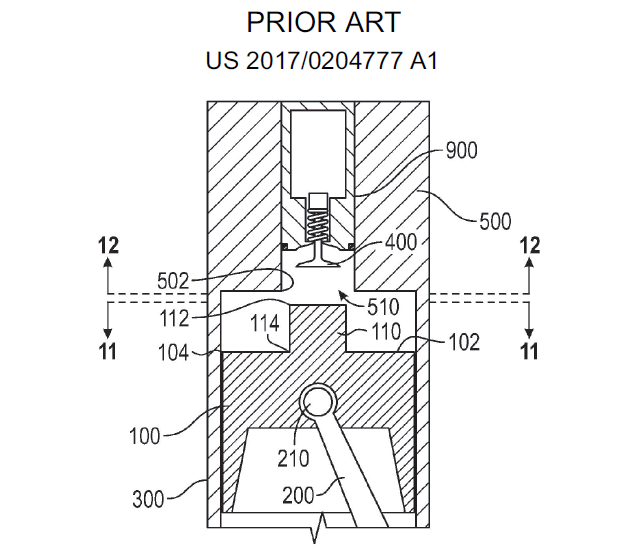
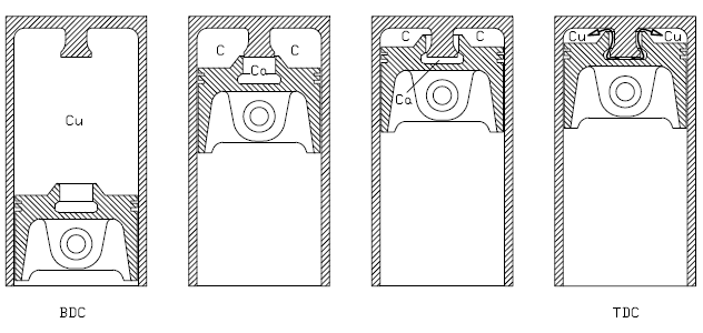
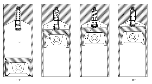
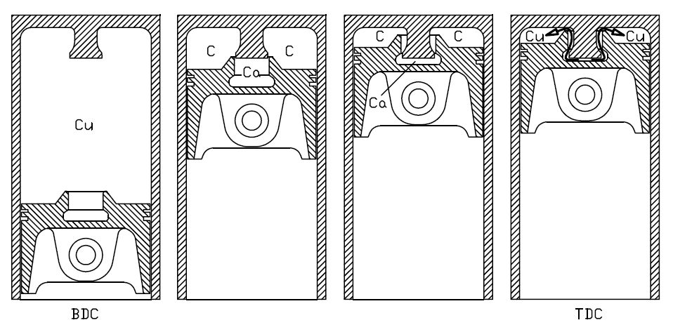
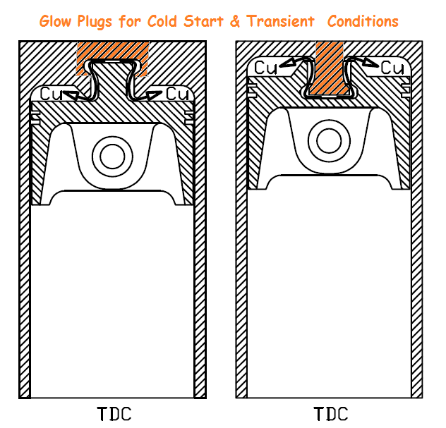
A characteristic of the PatBam is that the auxiliary chamber starts communicating with the main chamber just before the TDC, i.e. before any expansion in the pre-chamber (expansion means temperature drop).

Even if the HCCI combustion in the auxiliary chamber ends some 5 - 10 degrees before the opening of the “transfer ports”, after its combustion the burnt gas is further compressed; the compression tends to further rise the gas temperature, while the pre-chamber walls have not too much time to cool it down.

At the same time the mixture in the main chamber is further and further compressed, warmed and prepared to receive the active radicals from the auxiliary chamber just before the TDC.

The high pressure in the auxiliary chamber causes the penetration of the highly active radicals deep into the hot / compressed air-fuel mixture in the main chamber, triggering its HCCI combustion.


PatBam_15.png


By comparison,

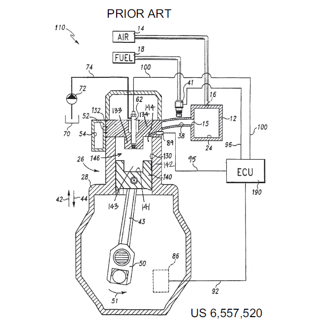
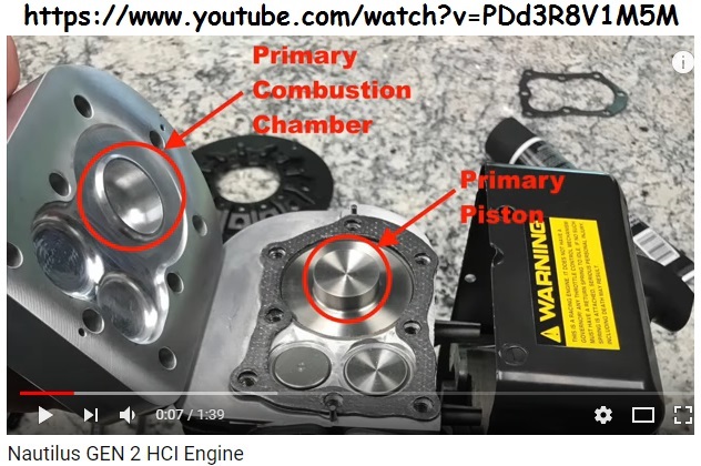
in the prior art (Chatterton, Roberts, Nautilus, etc) after its combustion in the pre-chamber, the burnt mixture undergoes a significant expansion: the volume in the pre-chamber over-doubles;

supposing adiabatic expansion in the pre-chamber, the absolute temperature of the burnt gas drops by more than 25% ((1/2)^0.4=0.75), say from 1700 degrees Celsius to only 1200 Celsius;

taking also into account the cooling affect of the surrounding pre-chamber walls (worth to mention here the longer time the gas stays in the pre-chamber after its combustion), when the two chambers eventually start communicating, the radicals are “semi-dead” (a big damage for the rest cycle) and the pressure is low reducing the penetration capability of the gas stream with the “semi-dead” radicals into the unburned mixture of the main chamber.

At the same time another “damage” is taking place in the main chamber wherein the compressed / warmed air-fuel mixture undergoes a significant expansion / cooling before the entry of the “radicals” from the pre-chamber: the temperature drop is more than significant; the absolute temperature of the air-fuel mixture in the main chamber drops by some 25% at the 33, or so, crankshaft degrees at which the two chambers unite (wherein the volume doubles with reference to the dead volume); a (main chamber) temperature drop from 630 deg Celsius at the TDC to only 400 deg Celsius when the two chambers start communicating makes the controllable HCCI difficult, if possible.


According the previous theory, with the PatBam things improve “square” relative to the prior art: way more active radicals penetrating way deeper into the main chamber wherein the conditions are way better for HCCI combustion.


The above in theory.


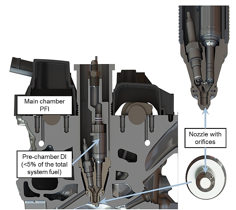
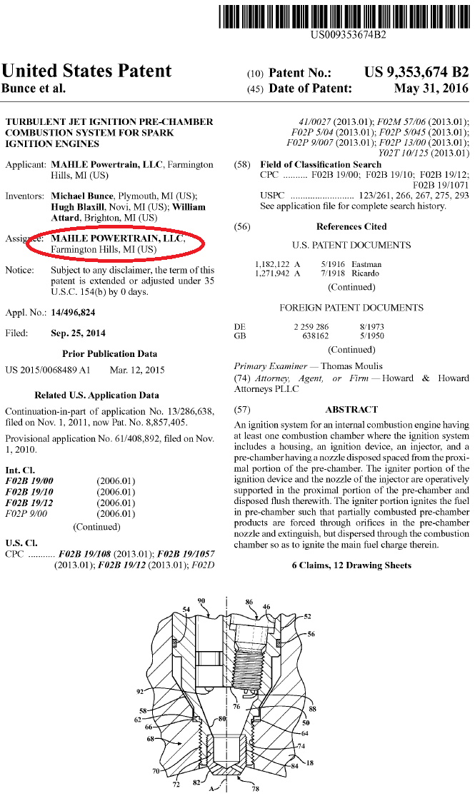
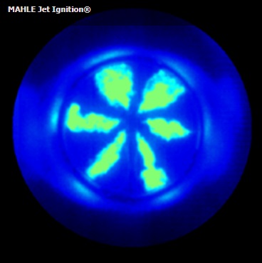
In practice, the TJI of Mahle says that the radicals of the PatBam will not put out as they pass through the “transfer pots”, streaming out from the pre-chamber to the main chamber.

In Mahle’s TJI the burnt and still burning gas passes through small orifices (0.7mm to 2mm diameter) to the main chamber, and there it ignites the rest mixture more or less like a fire gun.


You also write:


“Is the SkyActive engine turbocharged? If not, its compression pressure may be less than the highly turbocharged diesel with 14:1 CR.”


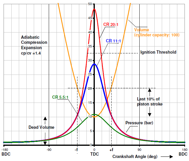
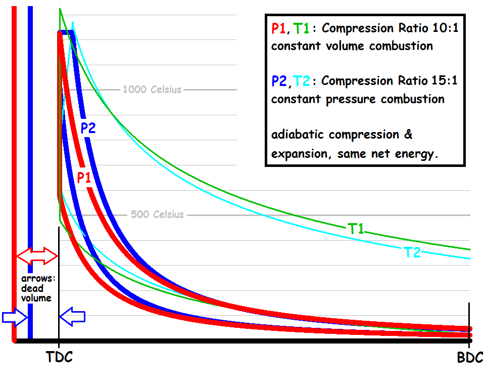
With 20:1 compression ratio (and without combustion) the maximum pressure (simpleminded approach: adiabatic compression, Cp/Cv=1.4) is 20^1.4=66bar, while with 14:1 compression ratio the maximum pressure is 14^1.4=40bar.


I.e. it is required more than 65% overboost in an engine having 14:1 compression in order the maximum compression pressure to rise to the level of a naturally aspirating engine having 20:1 compression ratio.


However, for more stable HCCI combustion at extra-lean mixtures what matters is not the maximum pressure in the cylinder, but the maximum temperature at the end of the compression.


In the typical supercharged / turbocharged engines the after-cooler cools down the compressed air.             


At a first approach (adiabatic compression), the ratio of the absolute temperature T2 of the air-fuel mixture at the end of the compression to the absolute temperature T1 of the air-fuel mixture at the beginning of the compression equals to:


T2 / T1 = CR^(1-Cp/Cv) = CR^0.4


For same initial temperature (say, 300K / 27Celsius), the 20:1 compression ratio of the SkyActive-X gasoline gives a final temperature T2=721 degrees Celsius, while the 14:1 compression of the SkyActiv-D Diesel gives a final temperature T2=589 degrees Celcious (which is 132 degrees Celcious colder).


With 73 degrees Celsius air temperature after the after-cooler of the turbocharged Diesel (14:1 compression ratio), the temperature at the end of the compression is the same 721 degrees Celsius as above.


You also write:


“"Fireballs" require flame propagation to form. Flame propagation does not occur beyond some lean limit.”


But, what else is the auxiliary chamber than a “fireball” generator?


For the compressed, but not yet burned, mixture, it is the same either a “fireball” grows somewhere in the combustion chamber, or the burnt gas from the auxiliary chamber bursts into the main chamber through the “transfer ports”.

In the one case it is required stratified charge and a spark plug, in the other case it is required an anvil whereon the lean mixture is “hammered” to auto-ignite.


Quote from http://articles.sae.org/15622/

From 18:1 to 15:1 CR

SpCCI is a progression of Mazda’s comprehensive Skyactiv efficiency-improvement initiative unveiled in 2011, which debuted gasoline and diesel engines with a common 14:1 compression ratio (CR). The new Skyactiv-X engine operates at a 15.0:1 CR, according to company engineers.

“We selected 15:1 compression ratio as it is close to compression-ignition conditions in normal ambient temperatures,” explained Powertrain Executive Officer Ichiro Hirose. “The spark creates an expanding fireball that acts like a secondary 'air spring' to create additional compression. Because the spark plug creates this fireball, it effectively controls the switch between spark ignition and compression ignition,” he noted.

Hirose added that achieving a “super-high compression ratio was a key breakthrough in realizing combustion with a lean fuel-air mix. Secondly, the leaner you make the air-fuel ratio, the more the specific heat ratio increases. To make the big step forward we needed to double stoichiometric levels from 14.7:1 to 30.0:1, at the very minimum.”

As AE reported previously, during Skyactiv-X’s development through G1, G2, and G3 program stages, engineers targeted an 18:1 compression ratio at lambda 2.5—a 40% improvement in thermal efficiency by setting the ideal pressure and temperature for homogeneous-charge compression ignition.

A key to Mazda’s achievement for the production engine is precise control of the combustion process (see SAE Technical Paper http://papers.sae.org/2015-01-1803/). The SpCCI engine uses pressure sensors in each cylinder to enable real-time temperature and pressure monitoring, in addition to other engine parameters. The engine-management system controls the twin electrically-variable camshafts, the new split-injection strategy that operates at 500 bar (7252 psi) and the air pump. The latter is a unique Roots-type device engineered by Eaton Corp. for the Mazda SpCCI application, Automotive Engineering has learned.

Supercharging and exhaust gas recirculation are known to be effective for operating an HCCI engine in CI mode at high loads. But as of 2013, Mazda R&D was aiming to achieve successful lean-burn HCCI within a broad load range using normal aspiration, according to Takahisa Sori, then Managing Executive Officer for R&D. Sori's engineers were concerned about an air pump compromising real-world fuel economy.

Speaking with Automotive Engineering, Sori also was bullish on the potential of mating HCCI gas engines with hybrid-electric drivetrains that let the engine run in its most efficient operating range, with e-motor assist as needed. In this de-emphasized role, the electric motor and battery can be downsized, reducing their cost. Such an arrangement would seem to be ideal for collaborative work with Toyota hybrid systems engineers.

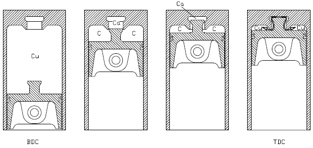
SpCCI’s air-fuel mixture is created by two-phase, split injection on the intake and compression strokes. A strong swirl is created in the combustion chamber to create an intentionally uneven distribution of fuel density, with a lean mixture around the periphery for CI and a relatively rich air-fuel mixture around the spark plug in the center—conducive to creating the fireball.

Spark ignition is used to start the engine and under heavy-load conditions, but the switchover to CI is not at any predetermined point. When the right intake-charge boundary conditions are achieved, the expanding fireball in the combustion chamber is created, with SI providing additional compression to the geometric compression ratio of approximately 15-16:1. This reaction induces CI, Hirose explained.

He noted that manufacturing costs for the SpCCI engine fall between those of a diesel and a gasoline engine.


End of Quote


It seems that the name SpCCI (Spark controlled Compression Ignition) used by Mazda for their SkyActiv-X, denotes that it is not a Homogeneous engine, but a stratified charge engine (as explained in the above quote).

The high pressure (500bar) direct injection provides a rich charge around the spark plug, keeping the mixture in the rest chamber lean.


One of the advantages claimed for the true Homogeneous charge is the reduction of the particulates.  


You also write:


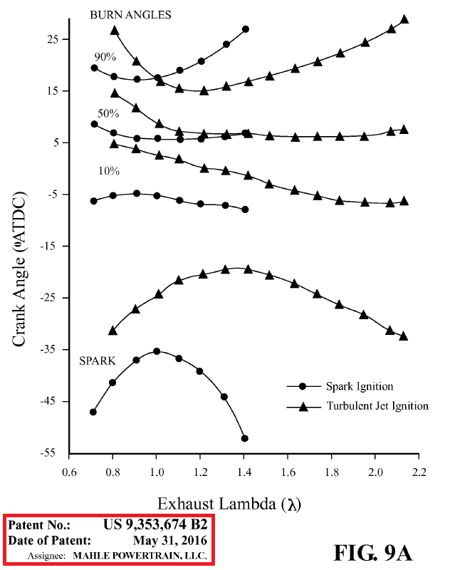
“Consider the TJI system. A jet of radicals produced by the combustion of a rich mixture in the pre-chamber, contacts large regions of the main chamber in a very short space of time. Combustion is very rapid and temperatures and pressures rise very quickly but HCCI does not occur and reliable combustion only extends to about lambda 2.2”


Fig25.jpg


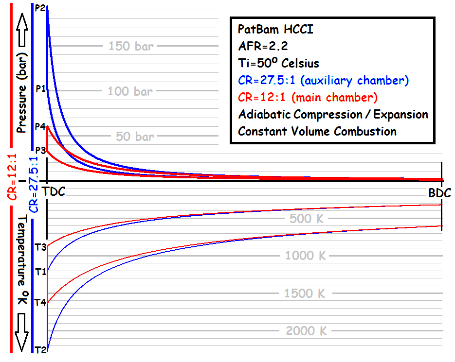
In the PatBam the air-fuel mixture in the main chamber is bellow, but near, the threshold for auto-ignition.


When the burnt gas from the auxiliary chamber bursts into the main chamber though the transfer port, just at the TDC, the conditions are for HCCI.


Depending on the octane number of the gasoline, the necessary compression ratio in the main (and in the auxiliary) chamber is defined.

The lower the octane number, the better, because the engine needs not extreme compression ratios.


Now the lower octane gasoline appears the better.


Thanks

Manolis Pattakos


Edited by manolis, 07 December 2017 - 13:53.


#17 gruntguru

gruntguru
  • Member

  • 7,642 posts
  • Joined: January 09

Posted 07 December 2017 - 23:55

OK I'm starting to see a path here. However I think you will need a high compression ratio in the main chamber to achieve the required "near HCCI" temperatures prior to pre-chamber discharge.


My reference to "fireballs" was directed at this:-


"In the PatBam the principle is different. 

Millions of active radicals (being generated into the auxiliary chamber) spread into the compressed mixture in the main chamber, just before the TDC, each acting as a spark. 

While the ignition is not stable (due to the extra lean or lean mixture), from the millions of ignitions some will propagate a little, increasing the pressure and temperature into the cylinder and causing the auto-ignition of the compressed mixture. 

For instance, if for every 1,000 radicals the 999 put out and only the one causes a tiny “fireball” of, say, 0.1mm diameter, the temperature increase will cause the HCCI combustion of the mixture in between neighboring “fireballs” (theoretically). 

I.e. the PatBam does not rely on a flame development / propagation mechanism at all."


Generation of the "mini fireball" still relies on flame propagation.

Are "millions of active radicals" generated by HCCI in an ultra-lean mix in the pre-chamber? The TJI has a richer mix in the pre-chamber.


My reference to effective CR in the Skyactive Mazda was speaking to pressure and the need for robust construction you spoke of - not temperature.


#18 manolis

manolis
  • Member

  • 935 posts
  • Joined: May 03

Posted 08 December 2017 - 14:53

Hello Gruntguru.


You write:


OK I'm starting to see a path here. However I think you will need a high compression ratio in the main chamber to achieve the required "near HCCI" temperatures prior to pre-chamber discharge.”


Yes, a high compression ratio in the main chamber is required.


But, how much high?”


It depends on the fuel, on the size of the auxiliary chamber, etc.


With gasoline having lower octane number, the required compression ratio in the main chamber drops.


For instance, with pure n-heptane, a 10:1 compression ratio in the auxiliary chamber and a 7:1 compression in the main chamber may be fine.


Simpleminded calculations:


The isooctane fuel has an auto-ignition temperature of 447 deg. Celsius (720K).


The n-heptane fuel has an auto-ignition temperature of 204 deg. Celsius (477K).


Applying the two equations:


P1*V1^(Cp/Cv)=p2*V2^(Cp/Cv) (adiabatic compression)


and


P*V=n*R*T,


the ratio of the compression ratios required for the auto-ignition of the isooctane and of the n-heptane is 2.8.


For instance, if the isooctane needs a 22:1 compression ratio to auto-ignite, the n-heptane needs only 22/2.8=8:1


It seems, the HCCI needs not extreme compression ratios (which go together with increased thermal and mechanical losses and with the need for robust / expensive engine structure).


If it was to be used n-heptane in a PatBam, a 7:1 compression in the main chamber, and a 10:1 compression ratio in the auxiliary chamber seem OK.


Strange, however it seems that with a cheaper / lower octane fuel (say, regular gasoline), things work better and more efficiently than with a high octane fuel (say, premium gasoline).

The price of the premium gasoline is some 10-15% higher than the regular.


premvreg.png


The PatBam seems to function better on even cheaper gasoline (say, 50RON).


The ideal fuel for the PatBam seems to be a volatile Diesel fuel (say like the n-heptane which is volatile and has about the same auto-ignition temperature with the Diesel fuel).


With the PatBam the running cost drops “square” due to the better fuel efficiency of the HCCI combustion, and due to the lower price, per litter, of the substantially lower octane fuel.


The increase of the capacity of the auxiliary chamber lowers the required compression ratio in the main chamber: when the two chambers start communicating a little before the TDC, the more the burnt gas in the auxiliary chamber, the stronger the impact on the temperature and pressure on the air-fuel mixture in the main chamber.


You also write:


Generation of the "mini fireball" still relies on flame propagation.

Are "millions of active radicals" generated by HCCI in an ultra-lean mix in the pre-chamber? The TJI has a richer mix in the pre-chamber.”


The combustion in the auxiliary-chamber of the PatBam is HCCI no matter how lean the mixture is (all it takes is an adequately “high” compression ratio therein, to shift the conditions above the threshold for auto-ignition).


The question is whether the burnt / burning gas exiting from the auxiliary chamber can ignite the lean mixture of the main chamber.


Even in case of progressive combustion (for similarly lean mixture in the main chamber), the PatBam appears better than the Mahle TJI because in the TJI the burnt gas just “blows” into the main chamber (the pressure in the pre-chamber of Mahle cannot increase significantly above the pressure in the main chamber because the orifices remain permanently open), while the burnt gas from the auxiliary chamber of the PatBam bursts deeper and faster into the main chamber.


PatBam_16.png

But the objective of the PatBam is not to accelerate the progressive combustion (as the TJI does), but to trigger an HCCI combustion simultaneous at all points (multi points) throughout the ends of the main chamber.


Thanks

Manolis Pattakos


#19 gruntguru

gruntguru
  • Member

  • 7,642 posts
  • Joined: January 09

Posted 11 December 2017 - 04:37

Hi Manolis.

With ultra-lean HCCI in the pre-chamber, the gases discharging to the main chamber will:

a) be fully combusted - HCCI is very rapid.

b) probably not contain free-radicals - I don't think they will form at ultra-lean mixtures.

So I think you will be relying on heating alone to tip the main chamber over the ignition threshold.


Regarding CR. Don't place too much emphasis on mechanical stress created by elevated CR. HCCI itself will produce high stress levels due to the high rate of pressure rise. The CR needs to be high enough to:

a) exploit the TE benefits of higher CR

b) ensure reliable ignition of (variable quality) fuels under the full range off operating conditions - cold start, high altitude etc.

I think you should be thinking closer to 15:1 main-chamber and 30:1 pre-chamber. Remember this only equates to approximately 2:1 in the pre-chamber itself (plus some allowance for leakage).


Advertisement

#20 manolis

manolis
  • Member

  • 935 posts
  • Joined: May 03

Posted 12 December 2017 - 16:37

Hello Gruntguru.


You write:


“With ultra-lean HCCI in the pre-chamber, the gases discharging to the main chamber will:

a) be fully combusted - HCCI is very rapid.

b) probably not contain free-radicals - I don't think they will form at ultra-lean mixtures.

So I think you will be relying on heating alone to tip the main chamber over the ignition threshold.”


In the PatBam, the exact crankshaft angle at which the combustion completes in the auxiliary chamber is not important because after the “very rapid” combustion, the burnt gas is further compressed until the “transfer ports” to open a little before the TDC.

Either the combustion ends at 25 degrees before the TDC, or at 15 degrees before the TDC, at the opening of the “transfer ports” the pressure and temperature in the auxiliary chamber will be, more or less, the same.


Quote from http://advtechconsultants.com/HCCIEngine.htm :


Homogenously Charged Compression Ignition (HCCI) Engines

It  was shown that  H, OH, and HO2 radicals  play key role in autoignition process.  In general, the concentration of the hydrogen peroxide (H2O2) increases in time and then begins to decompose (at temperatures between 1050 to 1100 K) at high rate to hydroxyl (OH) radicals.  This reaction produces a large number of OH radicals, most of which then react with fuel molecules to generate water and heat. The increased temperature brings the system into a very effective chain branching state. The fundamental chemistry of HCCI autoignition appears to be identical to that of knock in SI  engines.  However,  the picture does not favor the notion  that “active radicals”  in the residual burned  gases survive both the exhaust and intake processes to play a role in HCCI autoignition process in the next cycle. 


End of Quote.


If the above quote is true, when the “transfer ports” of the auxiliary chamber open, lots of OH (and other) radicals are there; and getting into the compressed / hot air-fuel mixture in the main-chamber will cause its rapid HCCI combustion.


On the other hand, if the radicals die before the two chamber start communicating, then the combustion “will be relying on heating alone to tip the main chamber over the ignition threshold”.

In such a case, the capacity of the auxiliary chamber is of crucial importance.


You also write:


“Regarding CR. Don't place too much emphasis on mechanical stress created by elevated CR. HCCI itself will produce high stress levels due to the high rate of pressure rise. The CR needs to be high enough to:

a) exploit the TE benefits of higher CR

b) ensure reliable ignition of (variable quality) fuels under the full range off operating conditions - cold start, high altitude etc.

I think you should be thinking closer to 15:1 main-chamber and 30:1 pre-chamber. Remember this only equates to approximately 2:1 in the pre-chamber itself (plus some allowance for leakage).”


The compression in the auxiliary chamber will be as high as necessary to give stable combustion at all conditions therein. The 30:1 seems high but it may be OK on the reasoning that some of the charge will leak to the main chamber.


But the 15:1 compression ratio in the main chamber is too high.


In the following plot (a simple isentropic process):


PatBam_18.png


judging from the final temperatures of the cycles,

the “constant volume” combustion with 10:1 compression ratio (red curve) is only slightly less efficient than the “constant pressure combustion” with 15:1 compression ratio (blue curve).


If the friction is taken into account, the difference drops.


With HCCI combustion and heavy load, a 15:1 compression ratio will cause extreme loads on the kinematic mechanism, will require extra strong / heavy / expensive parts, and will spoil the combustion chamber compactness (thermal losses).


A, say, 7:1 compression ratio in the main chamber seems too low, but 10:1 seems a reasonable compression, while a 12:1 seems high.


It seems that a spontaneous combustion at the TDC (constant volume at the TDC) is the “holly grail” of Mazda.


Thanks

Manolis Pattakos


#21 gruntguru

gruntguru
  • Member

  • 7,642 posts
  • Joined: January 09

Posted 13 December 2017 - 22:40

I guess it depends on the AFR. For automotive use and low NOx, the AFR needs to be either held at 1.0 and use a 3-way cat or maintained above 1.2. The former will require throttling and suffer the ignition difficulties discussed earlier. The latter will require a high main-chamber CR to reach auto-ignition temperature at ultra-lean conditions. Pressure however, will not be excessive because of the lower combustion energy at  AFR = 1.2


Of course the ultra-lean automotive application will probably need super/turbo charging.


#22 manolis

manolis
  • Member

  • 935 posts
  • Joined: May 03

Posted 15 December 2017 - 04:40

Hello Gruntguru.


You write:

“I guess it depends on the AFR. For automotive use and low NOx, the AFR needs to be either held at 1.0 and use a 3-way cat or maintained above 1.2. The former will require throttling and suffer the ignition difficulties discussed earlier. The latter will require a high main-chamber CR to reach auto-ignition temperature at ultra-lean conditions. Pressure however, will not be excessive because of the lower combustion energy at  AFR = 1.2”


Quote from http://www.motortren...ch-technologue/


“Mazda claims the 2.0-liter Skyactiv X will meet or exceed the efficiency of the 2.2-literSkyactiv D diesel engine, making it 20 to 30 percent thriftier than the 2.0-liter Skyactiv G at a price that falls halfway between those engines.”


End of quote


According the above claim of Mazda,

their SkyActiv-X (a near HCCI combustion) engine running at an AFR=1.2 gives a higher BMEP than

their conventional Spark Ignition SkyActiv-G engine running at an AFR=1.0 (stoichiometric) and a “basic” 14:1 compression ratio.


The substantially more “constant volume combustion” of the “X” (relative to the “G”) SkyActiv means a higher peak pressure of the cycle.


Quote from http://www.sciencedi...378382014001271


1-s2.0-S0378382014001271-gr3.jpg

Abstract

Homogeneous charge compression ignition (HCCI) engines have potential to provide both diesel like efficiencies and very low NOx and particulate matter (PM) emissions. There is growing global interest in using alternative biofuels in order to reduce the reliance on conventional fossil fuels. Therefore this experimental study was carried out to investigate performance, combustion and emission characteristics of HCCI engine fueled with ethanol and methanol and compare it with baseline gasoline fuel. The experiments were conducted on a modified four-cylinder four-stroke engine at different engine speeds using port fuel injection technique for preparing homogeneous charge. To achieve auto-ignition of air–fuel mixture in the combustion chamber, intake air pre-heater was used. In-cylinder pressure data acquisition with subsequent heat release analysis and exhaust emission measurements were done for combustion and emission diagnostics. In this paper, effect of intake air temperature and air–fuel ratio on combustion parameters, thermal efficiency, combustion efficiency, ringing intensity and emissions in HCCI engine is analyzed and discussed. Results show that methanol and ethanol are good replacements to gasoline in HCCI combustion mode.

End of Quote


In the above plot (for gasoline fuel), it is interesting the big difference that makes a small increase of 30 degrees on the intake gas temperature Ti, also the rate of pressure rise.


It is also interesting the “delay” time, right plot, Ti=120 deg Celsius curve: the combustion starts some 8 crankshaft degrees after the TDC (wherein the pressure and temperature are maximized), with several times lower rate of pressure rise (slow combustion).


The left plot is for AFR from 2.0 to 2.6.

But according the right plot, a higher Ti (or, equivalently, a higher compression ratio) would make the HCCI combustion “almost spontaneous” at substantially higher AFR’s (say 5:1).


The following plot shows more clearly the “delay time” measured in a RCM machine (rapid compression machine):


Fig-5-Iso-octane-and-n-heptane-autoignit


It seems that the divided chamber of the PatBam can do a lot for the control of the HCCI combustion at a wider range of AFR.


The excessive compression in the auxiliary chamber auto-ignites the lean mixture therein, while the moderate compression ratio in the main chamber limits the peak pressure of the “constant volume combustion” making it affordable for the kinematic mechanism.


By the way, when the AFR is increased from 1.0 to 1.2, and the cycle remains the same (say constant volume combustion), then a 14%  (1.14=(1.2)^(1/1.4)) increase of the compression ratio keeps the peak pressure the same.


Thanks

Manolis Pattakos


#23 gruntguru

gruntguru
  • Member

  • 7,642 posts
  • Joined: January 09

Posted 15 December 2017 - 07:41

Thanks Manolis. Some quality information in that post.


It seems intake air temperature might be the best way to control HCCI in a PatBam engine that uses AFR to control load. Accurate and rapid control of Ti is difficult - perhaps air heated by the exhaust manifold mixed with ambient air and using a blending valve for rapid adjustment of Ti?


Electric air heater and rich mixture for cold starting?


Edited by gruntguru, 15 December 2017 - 07:42.


#24 manolis

manolis
  • Member

  • 935 posts
  • Joined: May 03

Posted 18 December 2017 - 15:03

Hello Gruntguru.


You write:


It seems intake air temperature might be the best way to control HCCI in a PatBam engine that uses AFR to control load. Accurate and rapid control of Ti is difficult - perhaps air heated by the exhaust manifold mixed with ambient air and using a blending valve for rapid adjustment of Ti?”


Besides difficult, the rapid control over the Ti introduces some side effects.

The hot intake reduces the quantity (the mass) of the air trapped into the cylinder. For instance, if the engine is to operate at an AFR=1.2, full load and HCCI, a substantially hotter air-fuel mixture in the intake manifold reduces the BMEP of the cycle.


You also write: 

“Electric air heater and rich mixture for cold starting?”


It is an option; however a conventional / cheap glow plug in a wall of the auxiliary chamber (as in the old pre-chamber Diesels) seems preferable for the cold start.


In the following plot (from the last post):


1-s2.0-S0378382014001271-gr3.jpg


with AFR=2.2, gasoline fuel and 1200rpm,


the most “constant volume combustion” is the purple curve (that for Ti=150 deg Celsius) wherein the combustion starts just before the TDC and ends quickly after, without compressing the already burnt gas (which happens in the green curve for Ti=160 deg Celsius).


From the 40bar peak pressure of the “pure compression”, and supposing adiabatic compression, the compression ratio is calculated at 14:1.


With constant volume adiabatic compression and (273+150) = 423K initial temperature, the final temperature without combustion is 942 deg Celsius :

423 * 14^((Cp/Cv)-1) = 1215K (= 942 deg Celsius).


In the PatBam,

starting with 50 deg Celsius intake temperature (which is less than the typical temperature into the engine compartment), AFR=2.2 and a compression ratio 27.5:1 in the auxiliary chamber (blue curves):


PatBam_19.png


the peak temperature without combustion is the same: T1=1215K (942 deg Celsius),

with the peak pressure (without combustion) being P1=103 bar.


For AFR=2.2, with the peak combustion pressure being, according the plot, 75/40=1.875 times the pure compression peak pressure (without combustion), the final peak temperature during the combustion rises at T2=2278K (2005 deg Celsius), with the peak combustion pressure being P2=194 bar.


Supposing:

that the main chamber (red curves) of the PatBam operates at 12:1 compression ratio,

that the 1/4 of the charge is trapped into the auxiliary chamber,

and that after the combustion into the auxiliary chamber (T2=2278K) the burnt gas burst into the unburned gas (T3=872K, P3=32bar) in the main chamber,

the final temperature at the TDC in the united combustion chamber of the PatBam is calculated at:


(1*2278+3*872 )/4 = 1224K = 951 deg Celsius, i.e. a little more than the case wherein the intake temp was increased at 150 deg Celsius with 14:1 compression ratio and AFR=2.2 (as in the plot, at right).


The previous are for gasoline.


However, it doesn’t make any sense to use high octane gasoline in an HCCI engine.


With lower octane fuel (cheap gasoline), the required compression ratios in the auxiliary chamber and in the main chamber (which are 27.5:1 and 12:1 respectively in the above example) will drop substantially.


For instance, with cheap gasoline of substantially lower octane number, the auto-ignition temperature drops a lot, the compression ratio in the auxiliary chamber can drop to, say, 20:1, the compression ratio in the main chamber can drop to, say, 10:1, while the capacity of the auxiliary chamber can decrease to trap only the, say, 1/8 of the lean mixture when the two chambers are sealed from each other.


With “constant volume” HCCI combustion and high rate of pressure rise, the higher compression ratios require more robust (and so expensive) kinematic mechanism, increase the mechanical friction and lower the rev limit.


An HCCI engine is to run from lean (say, AFR=1.2) to extra lean (say, AFR>2) mixtures.


With AFR=2.2 and 14:1 compression ratio (plot at top of this post), the peak combustion pressure is about two times the “compression” peak pressure.

For richer mixtures (say, AFR=1.2), with 14:1 compression ratio again, and “constant volume combustion” again (HCCI), the peak pressure of the cycle goes near 140bar (~doubles), which is substantially higher than the peak pressure of most modern turbo-Diesel engines.


In the case of the PatBam, the high compression ratio in the auxiliary chamber is OK because the resulting loads are a few times smaller, while the smaller compression ratio in the main chamber allows “constant volume combustion” without creating extreme loads on the kinematic mechanism.


The previous “analysis” is a simpleminded approach.


Following the pressures and temperatures, it seems the PatBam can work with extremely lean mixtures (say, for AFR equal, or even higher, than 2.5).


Based on the two plots at the top of this post,

and comparing the curve with AFR=2.5 and Ti=130 deg Celsius (left plot) with the curve with AFR=2.2 and Ti=120 deg Celcius (right plot),

the combustions look identical.


The 13.5% (=2.5/2.2) leaner mixture entering in the cylinder needs to be just 10 degrees hotter in order to get burnt the same exactly way in the cylinder!


In the case of the PatBam, it translates to a slightly higher compression ratio in the auxiliary chamber (there is such a margin), and/or a slightly bigger auxiliary chamber (there is margin for such an increase, too).


The following GIF animation ( PatBam HCCI ) shows all the previous (there is also a visual basic at http://www.pattakon....takonPatBam.htm


PatBam_HCCI.gif


When the two chambers are sealed from each other, the blue curve “brakes” into a green curve (for the main chamber) and into a red curve (for the auxiliary chamber).

When the two chamber unite, the blue curves show the pressures and temperatures.


The temperature vs the crankshaft angle plot, at the bottom of the animation, is easier.


Nothing was mentioned, so far, about “the radicals” or about the affect of the “burst pressure rise” in the main chamber when the two chambers of the PatBam start communicating.


If these two main factors, i.e. the “injection” of the radicals and the impact of the pressure in the main chamber, work too, the PatBam may operate with extremely lean mixtures (say 5:1) without the need for extreme compression ratio in the main chamber.


“Injection” of the radicals:

Just like in the old Diesels, wherein the Diesel fuel was injected by means of compressed air,

similarly in the PatBam the radicals are “injected” into the main chamber by means of the burnt gas exiting from the auxiliary chamber.


Thanks

Manolis Pattakos


Edited by manolis, 18 December 2017 - 15:08.


#25 gruntguru

gruntguru
  • Member

  • 7,642 posts
  • Joined: January 09

Posted 19 December 2017 - 05:04

Nice analysis Manolis. 

I haven't gone through it in detail but a couple of questions arise.

 1. If full load operation is at lambda 1.2 and you use enleanment to reduce load, the leanest mixture used will be much greater than 2.5, perhaps even leaner than 5.0?

 2. Trapping as much as 1/4 of the charge in the aux-chamber will diminish the primary benefit of your system. That is its ability to control the pressure rise due to combustion until after the aux-chamber communication port opens - regardless of the timing of HCCI in the aux-chamber. With a large aux-chamber volume, the pressure rise therein will create negative work if it occurs before TDC.

 3. Don't worry about high CR. Modern gasoline engines all seem to be 12:1 or more. The high CR is an important part of efficiency. A lean burn engine has lower peak pressure for the same CR. The PatBam (with relatively fixed ignition timing) is likely to be somewhat speed limited anyway.


#26 manolis

manolis
  • Member

  • 935 posts
  • Joined: May 03

Posted 20 December 2017 - 09:35

Hello Gruntguru


You write:


“1. If full load operation is at lambda 1.2 and you use enleanment to reduce load, the leanest mixture used will be much greater than 2.5, perhaps even leaner than 5.0?”


Provided the compression ratio in the main chamber is high enough to heat the lean mixture slightly below the auto-ignition threshold, then the compressed and heated (and combusted) gas from the auxiliary chamber will increase the temperature of the lean mixture into the main chamber above the threshold, just before the TDC, causing its auto-ignition.


The “small” difference from the prior art, turns into a big difference at operation: because in the PatBam the communication of the auxiliary chamber with the main chamber begins just before the TDC and maximizes at the TDC wherein the conditions seems to be the optimum for auto-ignition.


Even without combustion into the auxiliary chamber (suppose it contains only air), again the high compression in the auxiliary chamber increases the temperature of the gas therein, and as it bursts open into the main chamber it increases the temperature in the main chamber above the threshold for auto-ignition.

If there is some fuel in the auxiliary chamber, things get even better.


For a specific fuel (say, a volatile fuel having some 250 deg C auto-ignition temperature) the compression ratios in the two chambers can be optimised to allow high or very high (say >5.0) air fuel ratios (AFR).


You also write:


“3. Don't worry about high CR. Modern gasoline engines all seem to be 12:1 or more. The high CR is an important part of efficiency. A lean burn engine has lower peak pressure for the same CR.”


The 12:1 compression ratio may be too high when it is for true constant volume combustion.


In the presentation of the SkyActivX, Mazda blames their previous SI engines as non efficient due to the long duration of the combustion.


By the way, the OPRE / PatOP architecture with the pulling connecting rods:


PatOPbw.gif


OPREdwell.gif


provides some 30 to 50% additional time for more efficient combustion, either in Diesels or in SI engines; actually the pulling connecting rods make the cycle more “constant volume”.


What Mazda actually claims, is that the big percentage of the fuel is burnt at smaller actual expansion ratios than the typical expansion ratio of the SI engine. On this reasoning, the peak pressure into the cylinder has nothing to do with the peak pressure in case of constant volume combustion.


For instance, with 15:1 compression ratio (Mazda SkyAxtivX), AFR=1.2 and true constant volume combustion at the TDC, the peak pressure of the cycle is around 150 bar without turbo or supercharging.


In a Diesel (say, in the Subaru boxer 2.0lit, with 86mm bore), with 16:1 compression ratio, the peak pressure without combustion is 16^1.4=~48 bar at the TDC, which is more than 2.5 tons (25,000N, 5,500lb) peak force on each piston even at idling.

However, the rate at which the fuel is burnt keeps the cycle away from constant volume, lowering substantially the peak pressure:


boxer_diesel_indepth_table_1.jpg


boxer_diesel_indepth_graph_2.jpg


The question is whether the pressure itself, or the rate of pressure rise (dp/dt) or even the d2p/dt2 (jerk) cause the worse fatigue stress on the kinematic mechanism (and on the transmission system).  


The real improvement the HCCI brings about is the almost “constant volume combustion”.

An HCCI with 10:1 compression ratio in the main combustion chamber, may be similarly efficient with a Diesel having 16:1 compression ratio, because the first runs at almost constant volume combustion while the second runs at almost constant pressure combustion.

The SkyActivX of Mazda (which is an almost HCCI), in order to run on constant volume combustion, either it has to run on very lean mixture (otherwise the peak pressure of the cycle would be extreme), or as a normal Spark Ignition running on Atkinson / Miller cycle (LIVC etc) to limit the actual compression ratio.

But if you limit the HCCI at very lean mixtures, then, only at specific conditions of revs / load the Mazda SkyActive-X could operate on HCCI


The drawback of the almost constant volume combustion is the extreme peak pressure of the cycle in case the engine operates at high compression ratios.


If at 1,500rpm the combustion duration is, say, 4 crankshaft degrees (as many experimental plots in the Internet suggest), at 6,000rpm the combustion duration is still small (~16 degrees without taking into account the increased turbulence / swirl etc).


You also write:


“2. Trapping as much as 1/4 of the charge in the aux-chamber will diminish the primary benefit of your system. That is its ability to control the pressure rise due to combustion until after the aux-chamber communication port opens - regardless of the timing of HCCI in the aux-chamber. With a large aux-chamber volume, the pressure rise therein will create negative work if it occurs before TDC.”


The modern Diesels are designed for a fuel having some specific characteristics (cetane number etc).


Similarly for the Spark Ignition engines (Ron number, volatile fuel, etc)


Provided the PatBam HCCI is design for a specific fuel (volatile, having low auto-ignition temperature), the sizes of the two chambers (auxiliary and main) can be optimized, as well as their compression ratios.


The combustion into the auxiliary chamber can end just before, or even a little after, the opening of the transfer ports.


The large auxiliary chamber in the example of the previous post was used to show that, even with gasoline fuel (high auto-ignition temperature), even without radicals and without pressure shock, the PatBam geometry can work.


You also write:

“The PatBam (with relatively fixed ignition timing) is likely to be somewhat speed limited anyway.”


According the graph at the top of the last post, a small increase of the intake temperature causes a significant shift of the peak pressure towards the TDC.


It seems that the limited speed of the existing HCCI comes from the fact that the peak pressure occurs after, or substantially after, the TDC, wherein the pressures have fallen.


If we could run the typical HCCI engine at double compression ratio (higher temperatures, faster combustion), its rev limit would be as high as that of the conventional SI engine.


With the PatBam, the small chamber manages to high pressures to auto-ignite in the proper time, and immediately to trigger the main chamber to auto-ignite.


Thanks

Manolis Pattakos


#27 manolis

manolis
  • Member

  • 935 posts
  • Joined: May 03

Posted 30 December 2017 - 04:43

Hello all.
 
 
In the following two gif animations for an HCCI 2-stroke OPRE-TILTING PatBam :
 
PatBam_Tilting_3.gif
 
PatBam_Tilting_4.gif
 
the extended piston dwell at the Combustion Dead Center, increases the useful rev range wherein the engine runs on HCCI.


Quote from Mazda's SkyActiv-X analysis at https://insidemazda....ss-information/
 
Range when HCCI could take place before the SKYACTIV-X:
 
Mazda_Next-Generation_Technology_E003-76
 
Mazda's SPCCI:
 
Mazda_Next-Generation_Technology_E004-76
 
The expanded range of SPCCI (combustion ignition):
Mazda_Next-Generation_Technology_E007-76
 
End of quote


Provided the above data / plot of Mazda is correct,
in the OPRE-Tilting PatBam HCCI (with the about 40% longer piston dwell at the Combustion Dead Cender) the "combustion ignition" range extends all the way from the minimum to the maximum revs of the engine. 
 
 
The animations show that at the TDC the communication between the two chambers maximizes (the auxiliary chamber is defineds by the bowl on the crown of the left / upper piston and by the "anvil" on the crown of the right / lower piston). 
 
 
Other characteristics of the OPRE-Tilting PatBam HCCI:
 
The compact and fully symmetrical structure (perfectly vibration free).
 
The absence of spark plugs and of high voltage circuit makes the engine simpler and more reliable (instead of putting double spark plugs per cylinder and two independent high voltage circuits, as is the case in aero engines, the spak plugs and the high voltage circuits are eliminated).
 
The extreme capacity to weight ratio, as shows the proof of concept OPRE-Tilting prototype (videos at http://www.pattakon....akonTilting.htm ) where a lot of material can be removed to further reduce the weight:
 
OPRE_tilting_prot_1.jpg
 
333 cc, bore 84mm, stroke 30+30=60mm 
(same bore to stroke ratio with BMW's boxer R1200GS of 2013) 
weight: 8.5Kp (19lb) without the exhaust pipe and the carburetor 
height: 250mm
 
 
The absence of reed valves: the tilting valve formed at the small end of the connecting rod makes things simpler (less moving parts) and more reliable.
 
The "cross-uniflow" scavenging (two extra-shallow cylinders, each having its own input and exhaust ports arranged anti-diametrically) 
 
The small "dead volume" of the built-in scavenging pumps.
 
Thanks
Manolis Pattakos


#28 manolis

manolis
  • Member

  • 935 posts
  • Joined: May 03

Posted 03 January 2018 - 10:41

Hello all.
 
Here is a "more conventional" HCCI PatBam 2-stroke:
 
PatBam_Rod_1.gif
 
wherein the piston-ring of the auxiliary piston slides permanently onto the cylinder liner of the auxiliary chamber. 
 
Thanks
Manolis Pattakos


#29 Kelpiecross

Kelpiecross
  • Member

  • 1,730 posts
  • Joined: October 10

Posted 04 January 2018 - 03:46


A layout like this may also be good for a very high pressure steam engine.

#30 manolis

manolis
  • Member

  • 935 posts
  • Joined: May 03

Posted 04 January 2018 - 04:00

Hello Kelpiecross.


You write:


"A layout like this may also be good for a very high pressure steam engine."


Or, better, for an over-square 4-stroke, wherein the low flame propagation is a problem.


For normal “progressive” combustion (as in the Spark Ignition engines), the “strange” shape of the combustion chamber (when the piston is at the TDC, the “dead volume forms a long “holed” cylinder) would be a problem (increased thermal loss etc).


But with HCCI combustion (they also call it: Low Temperature Combustion / LTC) there is no flame propagation, nor “flame front”; instead the combustion is spontaneous (it completes into, say, 10 crankshaft degrees while in a similar Spark Ignition engine the combustion extends along more than 50 crankshaft degrees) and by far colder (not allowing NOx formation).


The “cross shaped area” between the four valves (at the middle of this “cross” is where now the spark plug is located)


Ducati_Panigale_flow_restrictions.jpg


can be used as the bottom passage of the small diameter cylinder of the last animation, leaving the poppet valves as big as they are now.


The over-square design of the Panigale 1299 (1.91 bore to stroke area) fits with the spontaneous HCCI / LTC combustion.


According the Internet, the big Ducati uses at some revs / load nearly 60 degrees spark advance.


It is interesting to think about it:


A spark occurs now, and a tiny fire-ball starts extending as it consumes the fuel it finds just outside its periphery (the small volume to surface area of the still tiny fire-ball makes its growing harder).


And the pressure and temperature into the cylinder are still too low, keeping lower the rate of increase of the fire-ball diameter.


After some 40 degrees (~20 deg before the TDC) the fire-ball is big enough and the pressure and temperature are high enough to accelerate the progressive combustion.


But the combustion cannot help completing substantially after the TDC (say 50 crankshaft degrees, or even later), causing a strong reduction of the thermal efficiency: because the actual expansion-ratio of a fuel quantity burnt at, say, 30 crankshaft degrees after the TDC is about half than the actual expansion-ratio of a quantity of fuel burnt at the TDC.


Thanks

Manolis Pattakos


#31 manolis

manolis
  • Member

  • 935 posts
  • Joined: May 03

Posted 17 January 2018 - 15:31

Hello all.
 
The following animation has been added at the bottom of the http://www.pattakon....takonPatBam.htm web page.
 
PatBam_Valves.gif
 
It is a four-stroke PatBam HCCI control. 
 
Exhaust valve: red. 
Intake valve: blue. 
Auxiliary chamber "anvil": black.
 
Thanks
Manolis Pattakos 


#32 manolis

manolis
  • Member

  • 935 posts
  • Joined: May 03

Posted 21 January 2018 - 16:45

Hello all.


Here is a youtube video - animation  of the PatBam HCCI in a 4-stroke engine:


Thanks

Manolis Pattakos


#33 Kelpiecross

Kelpiecross
  • Member

  • 1,730 posts
  • Joined: October 10

Posted 23 January 2018 - 02:48


Manny - I couldn't find your last post on your "flyer" - so I thought I would put this here:

http://www.abc.net.a...d-falls/9133662

This just as likely to kill you as your arrangement - but it will do so without cutting your head off first.

Like your gadget I think it would be far more practical if the jets were mounted on a light frame of some sort so the pilot could sit.

#34 Kelpiecross

Kelpiecross
  • Member

  • 1,730 posts
  • Joined: October 10

Posted 23 January 2018 - 02:51


On the subject of your latest engine idea it would seem to me to be a "normal" engine (not HCCI) - but with a novel "ignition" arrangement.
Well worth building one to see how it performs.

#35 manolis

manolis
  • Member

  • 935 posts
  • Joined: May 03

Posted 24 January 2018 - 04:44

Hello Kelpiecross.


You write:

Manny - I couldn't find your last post on your "flyer" - so I thought I would put this here:

http://www.abc.net.a...d-falls/9133662

This just as likely to kill you as your arrangement - but it will do so without cutting your head off first.

Like your gadget I think it would be far more practical if the jets were mounted on a light frame of some sort so the pilot could sit. “


Yves Rossy thinks differently.


He needs not a seat to sit on, because he needs his body free.


As Rossy says : "I am the fuselage, and the steering controls are my hands, head and legs"


A big (or say “biiig”) problem with the jet packs is the extremely low fuel efficiency (calculating from the duration of the flight and the fuel consumed, the BTE is ~2%) and the small range.


When you secure the Portable Flyer on your body, say like:


PatTilt_Flyer.jpg


you can’t reach the rotating propellers, any longer.


The danger (beheading / injury) is for those standing near you; but why to stand near a guy who is taking off or who is landing?


With the same fuel, a conventional 2-stroke (running at, say, 20% BTE) gives ten times longer duration (100 minutes).


If we believe Mazda / SkyActiv-X (30% lower fuel consumption than conventional 4-stroke), with the HCCI combustion, the OPRE Tilting PatBam (which combines also the extended piston dwell at the combustion dead center, the low mean piston speed at higher rpm, the central ignition etc):


PatBam_Tilting_4.gif


is expected to give double BTE than a conventional 2-stroke.


With more than 3 hours duration of flight at 250 Km/h speed, the range is too long. And the fuel cost is lower than when you go to the destination by car or motorcycle.


While the existing jet packs seem nothing more than expensive toys, a Portable Flyer:


PatTol_axial_pilot2.gif


(more at http://www.pattakon....pattakonFly.htm )


can be the transportation means of the near future.


The two independent propulsion units (two engines side by side, with two counter-rotating propellers per engine) make it safer than the OSPREY:


Ossprey.jpg


Quote from http://www.pattakon....takonPatTol.htm :


Safety offered

As the Osprey, the Portable Flyer is capable for "vertical take-off / landing like a helicopter, and for long distance flights, like an airplane, at high speed and low fuel consumption. 

The malfunction of the one propulsion unit (due, for instance, to an engine failure, or to a rotor breakdown, or to a broken tooth-belt etc) is not fatal because the other (completely independent) propulsion unit, alone, is capable for the safe landing of the Portable Flyer. 


In the Osprey V-22 the malfunction / collapse / breakdown of the one rotor may turn out fatal, especially during a vertical take-off or landing. 


In comparison, the Portable Flyer with the two OPRE Tilting engines is safer: 

The breakdown of a rotor of a propulsion unit is not fatal: the other propulsion unit of the Portable Flyer (comprising an engine and two counter-rotating rotors) enables a safe langing or, if necessary, the flight to the closest safe landing place. 

Even in the case wherein both propulsion units fail, or in case the Portable Flyer runs out of fuel, the Portable Flyer can still, using the rescue parachutes, land safely. “


Thanks

Manolis Pattakos


#36 manolis

manolis
  • Member

  • 935 posts
  • Joined: May 03

Posted 24 January 2018 - 05:48

Hello Kelpiecross.


You write:

On the subject of your latest engine idea it would seem to me to be a "normal" engine (not HCCI) - but with a novel "ignition" arrangement.
Well worth building one to see how it performs. 


The HCCI combustion happens in your car spark-ignition engine every time it is knocking.

But this is an uncontrolled / catastrophic HCCI.


If you fill your fuel tank with low octane gasoline, the knocking (HCCI) will be permanent.


For the HCCI combustion it is also used the term LTC (Low Temperature Combustion).

They could also call it “spontaneous combustion” (the spark ignition and the compression ignition continue burning, while the combustion in the HCCI – middle – is finished):


maxresdefault.jpg


No matter how they call it, it combines a substantially better, than the spark ignition engines, fuel efficiency with substantially lower emissions (NOx and particulates) than the compression ignition engines.


PatBam HCCI / LTC controllable combustion basic characteristics:


- Divided combustion chamber.

- High compression ratio auxiliary combustion chamber.

- Moderate compression ratio main combustion chamber: the air-fuel mixture is compressed / heated near, yet below, the auto-ignition threshold.

- The high compression ratio of the auxiliary combustion chamber causes the auto-ignition of the lean air-fuel mixture therein; the burnt gas bursts - through the "transfer ports", just before the TDC - into the main combustion chamber triggering its auto-ignition.


The combustion starts into the auxiliary chamber and is HCCI (compression ignition of a homogeneous mixture).


With the compression ratio in the main chamber adequately high, or with the octane number of the fuel adequately low, when the burnt gas from the auxiliary chamber bursts into the main chamber finding an air-fuel mixture near, but below, the threshold for auto-ignition, the combustion cannot help being HCCI / LTC, a controllable HCCI / LTC: the air-fuel mixture into the main chamber auto-ignites a few degrees after the moment the two chambers unite into one.


Here is a PatBam Cross-Radial PatAT HCCI:


PatBam_PatAT_Cross_Radial.gif


PatBam_PatAT_Details.gif


Among its characteristics:

 
"four-stroke-like" lubrication, 
turbocharged (if "assisted at cranking", the turbocharger can also serve as the scavenging pump), 
asymmetric transfer ending after the closing of the exhaust port, 
scavenging with air, 
early indirect fuel injection in the space under the piston crown (the formed air-fuel mixture is the last to enter into the cylinder, eliminating the loss of unburnt fuel towards the exhaust), 
full balanced, 
even firing, 
no need for high voltage electric system, 
better when running on cheap low-octane gasoline. 

The strange piston structure divides the combustion and the scavenging into stages. 
Near the TDC the HCCI combustion is divided in two stages: 
After the auto-ignition and the combustion in the auxiliary chamber, the burnt gas passes into the main chamber triggering the ignition of the air-fuel mixture therein. 
Near the BDC the scavenging is divided in stages: 
After the opening of the exhaust port and as the piston is further approaching the BDC, the transfer ports open and pure air from the turbocharger pushes the remaining burnt gas out of the cylinder; later the well prepared air-fuel mixture from the space underside the piston crown overfills the cylinder after the closing of the exhaust port. 
The scavenging completes with a gust of clean air from the turbocharger; this air pushes any fuel in the passageways of the "asymmetric" ports into the cylinder. 

The specific architecture minimizes the number of bearings and the frictional losses. 
It also minimizes the weight. 
Even when it runs extra lean (say, AFR=2) it can still provide top specific power.


Eliminating the high voltage circuit from an airplane / helicopter engine is a big deal for reliability.


Thanks

Manolis Pattakos


#37 Kelpiecross

Kelpiecross
  • Member

  • 1,730 posts
  • Joined: October 10

Posted 25 January 2018 - 02:23


You could well be right - but I think the time comes when you actually have to try something in real-life and not just endless theorizing. I like the layout where the little "piston" hangs down and the auxiliary combustion chamber is in the main piston - you could then have the little "piston" adjustable in height to test various compression ratios in the auxiliary chamber - and maybe continually adjustable in use to suit various conditions.
At least initially a sidevalve engine might be easier for testing.

#38 Kelpiecross

Kelpiecross
  • Member

  • 1,730 posts
  • Joined: October 10

Posted 25 January 2018 - 02:35

Hello Kelpiecross.
 
You write:
Manny - I couldn't find your last post on your "flyer" - so I thought I would put this here:

http://www.abc.net.a...d-falls/9133662

This just as likely to kill you as your arrangement - but it will do so without cutting your head off first.

Like your gadget I think it would be far more practical if the jets were mounted on a light frame of some sort so the pilot could sit. “


Yves Rossy thinks differently.
 
He needs not a seat to sit on, because he needs his body free.


As Rossy says : "I am the fuselage, and the steering controls are my hands, head and legs"
 
A big (or say “biiig”) problem with the jet packs is the extremely low fuel efficiency (calculating from the duration of the flight and the fuel consumed, the BTE is ~2%) and the small range.


When you secure the Portable Flyer on your body, say like:
 
PatTilt_Flyer.jpg
 
you can’t reach the rotating propellers, any longer.
 
The danger (beheading / injury) is for those standing near you; but why to stand near a guy who is taking off or who is landing?
 
 
With the same fuel, a conventional 2-stroke (running at, say, 20% BTE) gives ten times longer duration (100 minutes).
 
If we believe Mazda / SkyActiv-X (30% lower fuel consumption than conventional 4-stroke), with the HCCI combustion, the OPRE Tilting PatBam (which combines also the extended piston dwell at the combustion dead center, the low mean piston speed at higher rpm, the central ignition etc):
 
PatBam_Tilting_4.gif
 
is expected to give double BTE than a conventional 2-stroke.
 
With more than 3 hours duration of flight at 250 Km/h speed, the range is too long. And the fuel cost is lower than when you go to the destination by car or motorcycle.
 
 
While the existing jet packs seem nothing more than expensive toys, a Portable Flyer:
 
PatTol_axial_pilot2.gif
 
(more at http://www.pattakon....pattakonFly.htm )
 
can be the transportation means of the near future.
 
The two independent propulsion units (two engines side by side, with two counter-rotating propellers per engine) make it safer than the OSPREY:
 
Ossprey.jpg
 
 
Quote from http://www.pattakon....takonPatTol.htm :
 
Safety offered

As the Osprey, the Portable Flyer is capable for "vertical take-off / landing like a helicopter, and for long distance flights, like an airplane, at high speed and low fuel consumption. 

The malfunction of the one propulsion unit (due, for instance, to an engine failure, or to a rotor breakdown, or to a broken tooth-belt etc) is not fatal because the other (completely independent) propulsion unit, alone, is capable for the safe landing of the Portable Flyer. 


In the Osprey V-22 the malfunction / collapse / breakdown of the one rotor may turn out fatal, especially during a vertical take-off or landing. 


In comparison, the Portable Flyer with the two OPRE Tilting engines is safer: 

The breakdown of a rotor of a propulsion unit is not fatal: the other propulsion unit of the Portable Flyer (comprising an engine and two counter-rotating rotors) enables a safe langing or, if necessary, the flight to the closest safe landing place. 

Even in the case wherein both propulsion units fail, or in case the Portable Flyer runs out of fuel, the Portable Flyer can still, using the rescue parachutes, land safely. “
 
Thanks
Manolis Pattakos


It's a personal preference maybe but I would much prefer to sit down. Even with those water-jet flying machine gadgets I think a sitting down arrangement would be better and may even have practical applications.
You are right about the efficiency of the little jets - bloody terrible. Possibly it is time for a small jet with about maybe four times the thrust of a model engine (about 100 pounds) and maybe high-bypass turbofan for more efficiency and less noise. If a model engine can be built a somewhat bigger one should be possible - and model turboprop engines are already available. Also be good for ultralights etc.

#39 manolis

manolis
  • Member

  • 935 posts
  • Joined: May 03

Posted 25 January 2018 - 05:12

Hello Kelpiecross.


You write:

It's a personal preference maybe but I would much prefer to sit down. Even with those water-jet flying machine gadgets I think a sitting down arrangement would be better and may even have practical applications.


If you have to use your body as the fuselage and as the wing (either wearing a wing-suit or without a wing-suit (which means higher speeds)):


PatTol_axial_pilot3.gif


the seat becomes a problem.


I agree on that the seat gives the sense to the pilot / rider that he/she is in a helicopter.

But a Portable Flyer is more than a helicopter.

The pilot / passenger is not an idle weight (like a package of cement) any longer.

The pilot / rider is the flying machine.

As for the engine, it is there only to provide the required thrust.


A good, as transportation means, flying machine is, mostly, for high speed - high mileage flights, not for hovering. The hovering is required only from time to time (for take off, for landing, for rescue, for fun, for acrobatics).


If you look again at the photo with the guy wearing the OPRE_Tilting Portable Flyer protorype, there is a (red) saddle whereon he can seat. The saddle is also shown in the following drawing.


PatTilt_Flyer_Frame.gif


With only an altimeter and timer, Rossy uses his skin and ears as airspeed indicators. 
"You feel very well, you feel the pressure," Rossy says, "you just have to wake up these senses. Inside an airplane we delegate that to instruments. So we are not awake with our body." 


Do the birds need a seat?


Thanks

Manolis Pattakos  


Advertisement

#40 manolis

manolis
  • Member

  • 935 posts
  • Joined: May 03

Posted 25 January 2018 - 06:52

Hello Kelpiecross.


You write:


You could well be right - but I think the time comes when you actually have to try something in real-life and not just endless theorizing.”


We already have done it with some pattakon projects. And the real life proved the “theorizing” more than correct


See the cars with the pattakon VVA’s at the www.pattakon.com web site:


RenaultHonda1.jpg


or see the OPRE II Diesel:


Or the OPRE III Diesel:


Or the PatOP Diesel:


All started as theory (“endless theorizing”?) and then they were tried in real-life.


Look at the PatOP.

A prototype was designed and then it was made one, and only one, prototype engine.

Every part on it is highly unconventional.

Every part was made one only time.

The only things from the market are the piston rings (from a VW Tdi), the plain bearings (from a BMW 1600cc) and the injection system (from a cheap 4-stroke Chinese gen-set).


Show me in the web a Diesel (prototype or mass production) running better than the PatOP.


On the other hand, if what you mean is to put something in mass production, this is a different story, because the required funds belong to another order magnitude.


Have you ever tried to make a working prototype?

To make a running engine?

Only this way you can get the difficulty.

In case the prototype is for a highly unconventional engine or mechanism, the difficulty multiplies.


Everything starts as a theory.

The more you talk about the theory, the less the problems you will face when realizing the theory.

You can’t imagine how precious is a “third party” opinion (right or wrong, it doesn’t matter).

A technical forum is wherefrom one can gather “objections” / “weaknesses” for his still unproven theory.


You also write:


“I like the layout where the little "piston" hangs down and the auxiliary combustion chamber is in the main piston - you could then have the little "piston" adjustable in height to test various compression ratios in the auxiliary chamber - and maybe continually adjustable in use to suit various conditions.
At least initially a sidevalve engine might be easier for testing. “


The VCR would be good for optimizing (during the design of the engine) the compression ratio required into the auxiliary combustion chamber.

But at operation, and judging from the conventional Diesels, the complexity of a VCR may not justify the advantages it brings.

In the conventional Diesels a 20:1 compression ratio would great for cold cranking, while a 13:1 would be great for light load operation. Typically they compromise at a constant (say 16:1) compression ratio for all conditions.


Here is the prototype of Nautilus Engineering (based on a side valveengine):


Nautilus_Engineering_prot.jpg


The projection (the auxiliary piston) is on the main piston and the recess (the auxiliary combustion chamber) is in the cylinder head.


If it runs as they show / claim, do you see a reason for the PatBam HCCI not to run far better?


It is more than easy for the guys of Nautilus Engineering to modify slightly their prototype (all it takes is a transfer port on the top of the recess and a narrowing on the auxiliary piston) in order to check the improvement the PatBam HCCI brings about.


Because the PatBam HCCI does everything at the right time.


Thanks

Manolis Pattakos


#41 gruntguru

gruntguru
  • Member

  • 7,642 posts
  • Joined: January 09

Posted 25 January 2018 - 11:38

It's a personal preference maybe but I would much prefer to sit down. Even with those water-jet flying machine gadgets I think a sitting down arrangement would be better and may even have practical applications.
You are right about the efficiency of the little jets - bloody terrible. Possibly it is time for a small jet with about maybe four times the thrust of a model engine (about 100 pounds) and maybe high-bypass turbofan for more efficiency and less noise. If a model engine can be built a somewhat bigger one should be possible - and model turboprop engines are already available. Also be good for ultralights etc.

We didn't need to see all Manolis' graphics twice. Perhaps you could delete them when you quote such a lengthy post?


#42 Kelpiecross

Kelpiecross
  • Member

  • 1,730 posts
  • Joined: October 10

Posted 26 January 2018 - 05:06

We didn't need to see all Manolis' graphics twice. Perhaps you could delete them when you quote such a lengthy post?


I presume that you do realize that they are only electronic images on a screen and no ink or paper is involved?

#43 Kelpiecross

Kelpiecross
  • Member

  • 1,730 posts
  • Joined: October 10

Posted 26 January 2018 - 05:12


Manny - I have indeed made running prototypes - quite a few as it happens. There is a time for building and there is a time for theory. And it's also time that flyer flew - or at least attempted to.

#44 gruntguru

gruntguru
  • Member

  • 7,642 posts
  • Joined: January 09

Posted 26 January 2018 - 06:26

I presume that you do realize that they are only electronic images on a screen and no ink or paper is involved?

You know I am a tree-hugger and I am certain your post caused the loss of several trees.


Seriously - scrolling to the bottom of the page while all the images load can be quite tedious.


#45 manolis

manolis
  • Member

  • 935 posts
  • Joined: May 03

Posted 26 January 2018 - 10:34

Hello Kelpiecross.


You write:

Manny - I have indeed made running prototypes - quite a few as it happens. There is a time for building and there is a time for theory. And it's also time that flyer flew - or at least attempted to.” 


I am glad I found someone who has made quite a few running prototype engines;

because I wanna built a pair of running OPRE Tilting PatBam HCCI engines


PatTol_axial2.gif


to be used as the basis for a Portable Flyer, and fly with it (OK, at least attempt to).


If you are interested, and have the time, e-mail me (http://www.pattakon....akonContact.htm) your estimation / offer for the cost and the time required.


The project (step by step with photos and videos) could be published in this forum.


On the other hand,

it seems that today it is still “a time for theory”.


Because the PatBam HCCI project is a quite fresh project and we are still thinking the best ways to apply, optimize, test and present it.


For instance:


We are thinking whether to apply it on a 2-stroke unconventional engine (like the PPE, wherein the piston-rod offers the significant advantage of keeping the piston centralized minimizing the clearance between the “anvil” and the auxiliary “cylinder liner”) or to apply it in a conventional 4-stroke.


We are thinking of how small clearance between the piston and the cylinder liner can be used (a steel piston seems preferable). Have you any idea?


We are thinking of the materials to be used. For the “anvil” (i.e. the auxiliary piston) the lower part of an exhaust valve seems good. What do you think?


We are thinking of not using spark plugs at all, just glow plugs.


We are thinking of the optimum timing (i.e. what is the best crankshaft angle to open the “transfer port” and ignite the main chamber).


We are thinking of the optimum compression ratios (for the auxiliary and the main chamber).


We are looking for suppliers of n-heptane and iso-octane in order to make blends and test / optimize the octane number for the prototype engine (a low octane number is not good because it limits the compression ratio in the main chamber, a high octane number is not good because the kinematic mechanism will suffer from the high pressures and the friction loss will increase).


We are thinking whether a carburettor is a good selection (it can provide more homogeneous mixture and can give lower emission, however a carburettor on a new engine “sounds” as a problem).


Dozens of such questions (and basic decisions, each of which changes substantially the direction of the project) can be added to the above catalogue.


So, don’t underestimate the usefulness of a long discussion (i.e. of the theory), and try to contribute with pure technical arguments.


A good theory may save lots of time and money.

Just a wrong decision can cause the catastrophe.


As for the Portable Flyer (the following version needs not to take-off or land vertically; the wing-suit is not shown):


PatATi_airplane.gif


besides the “beheading issue” you already mentioned,

what other problems do you see as compared to the state of the art flying machines? (small airplanes, ultralights, helicopters, jet-packs etc).


Thanks

Manolis Pattakos


#46 gruntguru

gruntguru
  • Member

  • 7,642 posts
  • Joined: January 09

Posted 27 January 2018 - 03:54

N-heptane and iso-octane are used as reference fuels at any refinery that produces gasoline so should be possible to readily source. On the other hand your goal should be to develop the engine to run on fuel that is easily purchased. In your case this would be regular grade gasoline. To test higher or lower octane fuels just add premium gasoline or kerosene/diesel.


#47 Kelpiecross

Kelpiecross
  • Member

  • 1,730 posts
  • Joined: October 10

Posted 27 January 2018 - 04:42

Hello Kelpiecross.
 
You write:
Manny - I have indeed made running prototypes - quite a few as it happens. There is a time for building and there is a time for theory. And it's also time that flyer flew - or at least attempted to.” 
 
 
We are thinking whether to apply it on a 2-stroke unconventional engine (like the PPE, wherein the piston-rod offers the significant advantage of keeping the piston centralized minimizing the clearance between the “anvil” and the auxiliary “cylinder liner”) or to apply it in a conventional 4-stroke.
 
We are thinking of how small clearance between the piston and the cylinder liner can be used (a steel piston seems preferable). Have you any idea?
 
We are thinking of the materials to be used. For the “anvil” (i.e. the auxiliary piston) the lower part of an exhaust valve seems good. What do you think?
 
We are thinking of not using spark plugs at all, just glow plugs.
 
We are thinking of the optimum timing (i.e. what is the best crankshaft angle to open the “transfer port” and ignite the main chamber).
 
We are thinking of the optimum compression ratios (for the auxiliary and the main chamber).
 
We are looking for suppliers of n-heptane and iso-octane in order to make blends and test / optimize the octane number for the prototype engine (a low octane number is not good because it limits the compression ratio in the main chamber, a high octane number is not good because the kinematic mechanism will suffer from the high pressures and the friction loss will increase).
 
We are thinking whether a carburettor is a good selection (it can provide more homogeneous mixture and can give lower emission, however a carburettor on a new engine “sounds” as a problem).
  
 
Thanks
Manolis Pattakos


I would use a conventional 4-stroke engine. You will have enough unforseen problems trying to develop novel engine architecture (if that is the word) let alone develop the PatBam principle as well. And I would use an engine where it is simple to get the head off - maybe a pushrod engine or a SOHC with a rubber belt cam drive?

I would use a light alloy piston - a steel one would lead to other problems to complicate matters. But erosion of the piston by hot gases out of the ports could be a problem - but probably not for short term testing (It may have to use a steel or ceramic liner later on).

A whole exhaust valve would seem be the best idea - and maybe one of the sodium-filled variety for cooling - it will get pretty hot. I would thread the valve stem so that it can be easily adjusted for various CRs in the aux. chamber. The "anvil" height would be best to be externally adjustable without dismantling the engine too much.

I thought the whole idea was not to use a spark plug.

I imagine the timing would be similar to conventional spark ignition timing. Which raises the matter of varying the ignition point to suit the RPM and/or load. Normal spark ignition varies by up to 40 degrees or so you expect the PatBam would need to be similar. Vary the height of the "anvil" or just run the engine at the equivalent of full spark advance?

The aux. chamber would have to be at least 18:1 and maybe more as there will be quite a bit of leakage past the un-ringed "anvil" - should be variable (as above) for testing. The main chamber should also be high CR as well (maybe 10 or 12:1) to get it close ignition temperature and dense and also be variable (really should say "adjustable" rather than "variable") CR. Maybe by different thickness head gaskets or shims?

The engine will be running (if successful) on petrol - so I wouldn't bother with exotic fuel blends.

I would (and do) use a carburettor. Again on the grounds of keeping things simple. I use an S.U. carb. as they are simple, easily and widely adjustable for mixture and tolerant of all sorts of airflows (being variable venturi). And I had about ten of them at one stage.

In general - I think you are going to come up against all sorts of unforeseeable and unpredictable problems. I have had some experience of a 18:1 petrol running on compression ignition (a misbehaving Atkinson engine initially). Some odd characteristics: essentially running in extreme detonation conditions. As soon as detonation starts (after turning off the ignition) - the exhaust becomes a series of black puffs (this how they detected detonation on aero engines during the 1940s). Presumably unburnt fuel? So I imagine that in your aux. chamber ( which would be detonating?) you may not get the really good jets of flame to ignite the main chamber you expect. And (running on leaded petrol) the exhaust fumes are incredibly sharp (like teargas I imagine - not that I've smelt teargas). Probably full of peroxides?

As for the Flyer - I would run a mile from the Flyer - literally and figuratively. It would be an enormous burden on your resources and even if it did fly it would remain a (extremely dangerous but interesting) novelty like the other "flying man" contraptions. I think after years of many, many ideas for flying have been suggested and tried - the flying world has settled on something like the Robinson R22 as being the smallest and most practical flying machine for VTOL etc.

There is reasonable possibility that your PatBam could be made into something useful and sellable - so it is worth trying. But not the Flyer.

#48 Kelpiecross

Kelpiecross
  • Member

  • 1,730 posts
  • Joined: October 10

Posted 28 January 2018 - 02:16


A few more thoughts on the PatBam: even with a very high CR in the aux. chamber it will not ignite (detonate) until quite a high manifold pressure is reached (if you are using a throttled intake) - so you will need a spark ignition system for idling and low manifold pressure running. Which would negate the advantage of no ignition system. Also the mixture would have to be richer(normal AFR) while running as a "normal" engine.
But I can see the PatBam being slightly possibly useable by having the spark ignition at lower loads and then compression ignition at higher loads.

#49 manolis

manolis
  • Member

  • 935 posts
  • Joined: May 03

Posted 28 January 2018 - 06:19

Hello Kelpiecross.


You write:

I think you are going to come up against all sorts of unforeseeable and unpredictable problems.


Exactly.


Because the PatBam is a primitive / basic idea that can combine with everything existing (2-stroke and 4-stroke designs, single or multicylinders, giant - normal - tiny size engines, trunk piston and crosshead design, naturally aspirating and turbo/super charged).


Also because it over-simplifies the control over the HCCI combustion: compare it to the SkyActiv-X of Mazda that utilizes every existing high tech solution to do the same: to control the HCCI combustion.

According Mazda, the fuel consumption benefit of their HCCI is more than 20% over their current high-tech SkyActiv-G engines. And this is a big deal.  


Also because, if it works, it seems a quite promising solution for a big drop of the CO2, NOx and particulates emissions (the CO2 emissions represent the fuel consumption).


All these “unforeseeable and unpredictable problems” make the theoretical discussion interesting and productive.

A proof of concept prototype is significant and required; but if the Nautilus Engineering prototype does run as they show / claim, imagine how the PatBam HCCI would work.


You also write:

The engine will be running (if successful) on petrol - so I wouldn't bother with exotic fuel blends.


Yes, for the first proof of concept prototype.


However when you are looking beyond a demonstration (to the future?),

the theory points at (cheaper) fuels having lower octane number than the regular grade gasoline. They are not available today in the gas stations, but it is quite easy to be available tomorrow.

Strange it appears: we are not looking for a difficult to produce higher octane number gasoline, but for a lower octane number gasoline produced easily and cheaply from the current refineries.


The theory says that a 10:1 compression ratio in the main combustion chamber combined with true “constant volume combustion” can give a better fuel efficiency than the existing conventional Spark Ignition or Compression Ignition running at 14:1 compression ratio (as the Mazda SkyActiv-G gasoline and SkyActiv-D Diesel).


A 10:1 compression ratio limits the loads, reduces the frictional loss and enables a more lightweight and cheaper kinematic mechanism.


But if with 10:1 compression ratio and regular grade gasoline, the threshold for auto-ignition is substantially higher, a lower octane number gasoline would be better (alternatively the auxiliary combustion chamber can increase in size, but according the theory a big auxiliary chamber comes with drawbacks).


PatBam_12.png


You also write:

A few more thoughts on the PatBam: even with a very high CR in the aux. chamber it will not ignite (detonate) until quite a high manifold pressure is reached (if you are using a throttled intake) - so you will need a spark ignition system for idling and low manifold pressure running. Which would negate the advantage of no ignition system. Also the mixture would have to be richer(normal AFR) while running as a "normal" engine.
But I can see the PatBam being slightly possibly useable by having the spark ignition at lower loads and then compression ignition at higher loads. “


The PatBam is to run from lean to extra lean, as the compression ignition Diesels, without a throttle valve.


I.e. the quantity of the air entered / trapped into the cylinder is more or less constant. The load is defined by the quantity of the fuel (as in the Diesels).


The Diesels run fine at idling and light loads wherein the air fuel ratio is several times (even more than 10) higher than the stoichiometric.


Thanks

Manolis Pattakos


#50 manolis

manolis
  • Member

  • 935 posts
  • Joined: May 03

Posted 28 January 2018 - 07:00

Hello Kelpie cross.


You write:

There is reasonable possibility that your PatBam could be made into something useful and sellable - so it is worth trying. But not the Flyer.


It is good to know there are not obvious / strong / crucial disadvantages and that the PatBam HCCI idea is alive.   


You also write:

As for the Flyer - I would run a mile from the Flyer - literally and figuratively. It would be an enormous burden on your resources and even if it did fly it would remain a (extremely dangerous but interesting) novelty like the other "flying man" contraptions. I think after years of many, many ideas for flying have been suggested and tried - the flying world has settled on something like the Robinson R22 as being the smallest and most practical flying machine for VTOL etc.”


I would appreciate true strictly technical arguments.


Why you “would run a mile from the Flyer - literally and figuratively”?


Have you seen the wing suiters flying?


Have you seen how precisely they control their flight?


The worst moment is the landing.

If they don’t want to use parachute, things get from taugh to dangerous:


Wouldn’t a Wing-Suiter land safely on a road wearing this:


Wing_Suiter_Landing.jpg


lightweight casing?


He approaches tangentially the road, the wheels touch the road and the wing-suiter uses his body / wing-suit to brake / decelerate.


I can’t see something more dangerous than the landing of a small airplane on a field.

It is a way safer landing than on boxes (above video) or on water.


During the flight, the two front arms / wheels can be retracted.


Now put a completely neutral propulsion unit on the casing (no vibrations at all, no gyroscopic rigidity at all, just a thrust force pulling forwards):


PatATi_airplane1.gif


The Wing-Suiter not only can land on any road or flat field, but he can also take-off like a small airplane (no need for vertical take-off; the thrust force provided by the propellers needs not be bigger, any longer, than the total weight).


So, please enlighten me for the technical and the safety issues you see.


Because if I was a Wing-Suiter I would die (not literally) for a casing like the above, or better for a casing / propulsion unit like the above.


Thanks

Manolis Pattakos