Jump to content


Photo

Mystery rear upright/hub casting pattern


  • Please log in to reply
37 replies to this topic

#1 PZR

PZR
  • Member

  • 145 posts
  • Joined: August 14

Posted 09 January 2018 - 12:10

Bought from a London flea market, sold as a 'decorative item', a rear upright/hub wooden casting pattern.

Identified with a period-looking paper label as part of 'The Museum of London Reserve Collections', 'Accession number NN11781 (i)' and 'Wooden Pattern For Mould For Machine/Engine Part'. The museum is due to move in the near future and I presume they have been selling off some surplus from storage.


Overall dimensions are 380mm long, 210mm wide and 140mm deep, but I presume originally made to suit Imperial measurements.


I'm intrigued to know where it might have been from, and what vehicle it was for. Considering it came from The Museum of London Reserve Collection, could this have been from a London-based casting foundry, for a London-based customer?


What do you think?


HNpl3L.jpg

pCSXbX.jpg

4rbamL.jpg

AfMHjM.jpg

5FwM1d.jpg


Advertisement

#2 Allen Brown

Allen Brown
  • Member

  • 5,568 posts
  • Joined: December 00

Posted 09 January 2018 - 12:28

If you contact the Museum of London and quote that accession number, I'm sure they can tell you more.


#3 PZR

PZR
  • Member

  • 145 posts
  • Joined: August 14

Posted 09 January 2018 - 12:37

If you contact the Museum of London and quote that accession number, I'm sure they can tell you more.


Thanks but I tried, and they can't...


"Unknown Source".


#4 Cirrus

Cirrus
  • Member

  • 1,756 posts
  • Joined: February 03

Posted 09 January 2018 - 13:33

I'm inclined to think it's from the early sixties. As wheels got wider, uprights became "deeper" to clear the rims.


#5 Bloggsworth

Bloggsworth
  • Member

  • 9,509 posts
  • Joined: April 07

Posted 09 January 2018 - 15:05

Lotus 18/20/22/23/51 - Lola FJ/F3 - Alexis/Merlyn - 1960 on to late 60s in the case of the Lotus51. It's the type of hub used with the drive shaft as the top link.


#6 Ray Bell

Ray Bell
  • Member

  • 82,272 posts
  • Joined: December 99

Posted 09 January 2018 - 15:41

The caliper mounts will give a clue...

It's not for a drum-braked car, nor one with inboard brakes.

#7 PZR

PZR
  • Member

  • 145 posts
  • Joined: August 14

Posted 09 January 2018 - 15:52

Thanks for suggestions so far.


I'm familiar with similar designs having had to source a pair of new BT8 rear uprights a few years back, but this pattern looks kind of - how can I say - out of proportion? I can't get my head around the distance between the hub centre and the lower wishbone. It's something like 10.5 inches centre to centre. Seems to me that if the car got a puncture the wishbone and upright would be acting as a skid...  What am I missing? 


#8 mariner

mariner
  • Member

  • 2,401 posts
  • Joined: January 07

Posted 09 January 2018 - 15:57

It seem to have the boss for a top link bolt hole so it may not be for a driveshaft top link set up.


Interestingly  there is no apparent provision in the pattern for a void inside the main casting area below the hub. That would result in   a  very heavy upright.


could it be only part finished or a practice piece? 


#9 Ray Bell

Ray Bell
  • Member

  • 82,272 posts
  • Joined: December 99

Posted 09 January 2018 - 16:28

As Bloggsworth has explained, it's for a rear suspension using the driveshaft as a suspension member...

The boss above the bearing housing is for the longitudinal link from the chassis. I'd also suggest those squarish projections which have the black paint on them are to seat an inner core which provides for the upright to be hollow.

#10 Cirrus

Cirrus
  • Member

  • 1,756 posts
  • Joined: February 03

Posted 09 January 2018 - 17:52

Regarding the distance between the centre of the hub and the bottom wishbone pickup, it was not unusual for bottom pickups to be below the wheel rim. The problem with a tyre deflation is not so much the upright/wishbone skidding as digging in. I seeem to recall that problem being mentioned in connection with Jim Clark's accident.


My money would be that the pattern is for a Formula Junior upright from 1960-1962. Gemini, Britannia, Elva..?


Edit - just got a mate to look at a Britannia and although it uses the driveshaft as a top link, it's got fabricated uprights.


Edited by Cirrus, 09 January 2018 - 17:54.


#11 David Birchall

David Birchall
  • Member

  • 3,292 posts
  • Joined: March 03

Posted 09 January 2018 - 18:40

My first thought was Lotus 22-(there is a mount for upper link that was not used on the 18 or 20) but looking at photos of a 22 rear end the Lotus upright appears to slightly different at the top.  Almost certainly FJ I would agree.  Lotus, Brabham or Lola...


Edit:  I disagree that it used the driveshaft as a suspension member-if it did it would not require the upper link.


Edited by David Birchall, 09 January 2018 - 18:41.


#12 Cirrus

Cirrus
  • Member

  • 1,756 posts
  • Joined: February 03

Posted 09 January 2018 - 19:56

...but it would probably require a radius rod to control fore and aft movement. The top mount is closer to the driveshaft than it would have been if the upright had been designed for a conventional top link layout.


...possibly


Edited by Cirrus, 09 January 2018 - 19:59.


#13 Cirrus

Cirrus
  • Member

  • 1,756 posts
  • Joined: February 03

Posted 09 January 2018 - 20:09

If we're going down the FJ route, then the pattern probably comes from a reasonably well-known manufacturer. Pattern making was/is a skilled process and would probably have been beyond the financial means of a "backyard special".


Someone with more time on their hands than me might want to scrutinise the pictures on the FJ site http://formulajunior.com/fj-marques/ to see if anything looks likely.


Edited by Cirrus, 09 January 2018 - 20:12.


#14 PZR

PZR
  • Member

  • 145 posts
  • Joined: August 14

Posted 09 January 2018 - 20:27

Again, many thanks for all the suggestions so far.


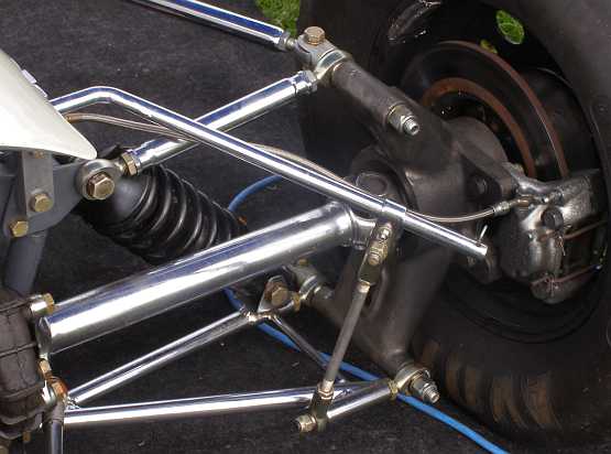
One of the reasons I spotted it - and bought it (it wasn't very much money) - was that I immediately recognised it as a pattern for a racing car hub/upright, and from a good distance away. It reminded me of the Brabham ones I had sourced a few years back, which were similar to this:


wbemEC.jpg


...on a Brabham which I photographed at Goodwood. Similar, but not the same.


I had imagined some sort of core being added (thanks Ray) as it would be pretty hefty without it, even in Mg.

Judging by the other casting patterns being sold alongside it (which all looked like props from Chaplin's 'Modern Times', more suitable for ship components than nice little racing cars) I wonder if it went to the museum via a London school or technical college, and had most recently been used as a teaching aid? 


Edited by PZR, 09 January 2018 - 20:30.


#15 Bikr7549

Bikr7549
  • Member

  • 364 posts
  • Joined: May 16

Posted 10 January 2018 - 03:09

If you have Costin and Phipps Chassis Design book take a look at the Lotus 33 rear suspension drawing on page 76-it has a very similar layout and appearance to this pattern. I am not saying it is from that car, just similar in proportions and has the drivehaft located high up. I cant find a photo of the 33 suspension but from the drawing it appears to have a single trsnsverse link on top. Brake caliper attachment is different.

Edited by Bikr7549, 10 January 2018 - 03:12.


#16 Ray Bell

Ray Bell
  • Member

  • 82,272 posts
  • Joined: December 99

Posted 10 January 2018 - 03:58

It's definitely not from a car with an upper suspension link, as the Lotus 33 had...

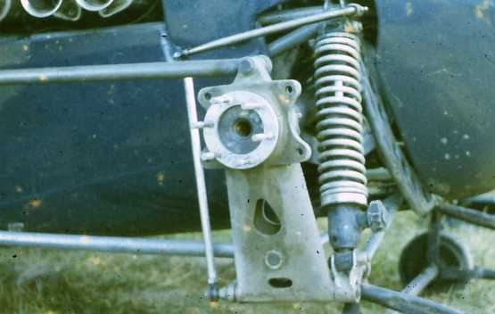
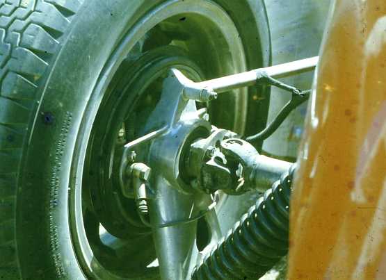
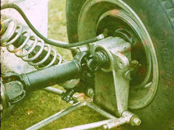
I have a bunch of upright photos here, all but two from a cars without a top link. The older photos were taken by Bob Britton in 1961/2, the rest by myself at Cadwell Park 18 months ago when the Historic Juniors were there.

The Elva 200 upright shows clearly the way an upright in a suspension using the driveshaft as a top link had to be mounted. This one had inboard brakes so there are no caliper mount lugs:

rearupright_Elva200.jpg

The Lightning has a top link, but it does appear to be an upright modified to be used with a top link after having been designed for a driveshaft of fixed length. This one has drum brakes so it also has no caliper mount lugs:

rearupright_Lightning.jpg

Not a good pic, but the Lola front-engined Junior had a fixed driveshaft and inboard brakes:

rearupright_Lola_Jr.jpg

Two views of the Lotus 18 F1 rear upright, showing the caliper mounts and attachment of the radius arms:

rearupright_Lotus18_F1.jpg

rearupright_Lotus18_F1_B.jpg

The Lotus 18 Junior, however, has a different casting to mount the drum brakes:

rearupright_Lotus18_Jr.jpg

Here's the Australian interpretation, Elfin's Catalina model with fixed driveshaft and a very ordinary drum brake mounting along with forward affixing of the radius arms to keep them out of the way of everything else:

rearupright_Elfincatalina.jpg

Finally, with top links and a doughnut for driveshaft length variation, this one is from an Alexis:

rearuprightalexis.jpg


.

Edited by Ray Bell, 10 January 2018 - 03:59.


#17 2F-001

2F-001
  • Member

  • 4,310 posts
  • Joined: November 01

Posted 10 January 2018 - 07:12

If the upright was intended for an installation with no separate upper transverse link, wouldn't the 'boss' at the top (the provision for a subsequent drilling - for a radius arm joint) have been more useful if transverse, or even vertical, rather than longitudinal?

Assuming that more vertical than lateral movement would be required, I'd have thought that some provision for a radius arm to be attached with a rose joint in a vertical orientation - with the bolt in double-shear - would have been preferable to this (if no upper link was intended).

(I've only just got up though, so fear my drowsy brain is missing something obvious...)


#18 Ray Bell

Ray Bell
  • Member

  • 82,272 posts
  • Joined: December 99

Posted 10 January 2018 - 08:25

Both the Alexis and Brabham examples above show this could be so...

However, I'm pretty focussed on the length of the upright and the number of cars of that time which did use the driveshaft as upper link.

#19 2F-001

2F-001
  • Member

  • 4,310 posts
  • Joined: November 01

Posted 10 January 2018 - 08:33

I wasn't doubting you, Ray - and certainly not your much greater personal knowledge of such cars... I was just wondering why it would be done that way!


Advertisement

#20 Ray Bell

Ray Bell
  • Member

  • 82,272 posts
  • Joined: December 99

Posted 10 January 2018 - 09:33

I don't know that my knowledge is so great, Tony...

And it's possible I'm barking up the wrong tree too!

#21 David Birchall

David Birchall
  • Member

  • 3,292 posts
  • Joined: March 03

Posted 10 January 2018 - 18:37

To my eye the orientation of the top lug is important.  The Alexis is the most similar of those Ray has shown-and it does not use the driveshaft as a suspension member. :)


#22 GMACKIE

GMACKIE
  • Member

  • 14,026 posts
  • Joined: January 11

Posted 10 January 2018 - 19:11

The rear uprights on my Jolus FJ were similar 'Mystery', with a lug at the top. They were cast from Bob Britton's pattern...as were the Lynx uprights.


Bob Joass originally used the 'driveshaft top link' arrangement, however on my car [originally Paul Bolton's], Bob Joass fabricated a bracket that bolted to that lug, to hold an adjustable top link. The driveshaft had sliding splines. Only one other Jolus had the adjustable top link...the Jolus Minx.


#23 Peter Morley

Peter Morley
  • Member

  • 2,263 posts
  • Joined: October 02

Posted 11 January 2018 - 10:21

If the upright was intended for an installation with no separate upper transverse link, wouldn't the 'boss' at the top (the provision for a subsequent drilling - for a radius arm joint) have been more useful if transverse, or even vertical, rather than longitudinal?

Assuming that more vertical than lateral movement would be required, I'd have thought that some provision for a radius arm to be attached with a rose joint in a vertical orientation - with the bolt in double-shear - would have been preferable to this (if no upper link was intended).

(I've only just got up though, so fear my drowsy brain is missing something obvious...)


Cars using the driveshaft as the top suspension link tend to predate the use of rose joints in the suspension, they would have used silentbloc rubber bushes that could be attached to this upright by clevis (Y) pins, which enable the vertical movement.


Similarly most cars that used the driveshaft upper link suspension would have had drum brakes rather than discs - why handicap themselves with such suspension when they have improved the brakes?


It could be that it was to upgrade a drum brake/driveshaft upper link car to discs - e.g. keeping the original suspension while upgrading the brakes.

That would date it to around 1961/62 as would the length of the lower part which suggests 15" or bigger wheels (which dropped out of popularity around this time as well).


The spacing of the caliper mounts suggests a pretty small disc but that might not be surprising in the early days of discs.


Fabricated uprights were very unusual at that time so it's possible that something like the Britannia that is running fabricated uprights might not have its original uprights?

The cost of making new uprights from scratch (e.g. new patterns) for an unusual car might not have been cost effective compared to fabricating replacements.


#24 Ray Bell

Ray Bell
  • Member

  • 82,272 posts
  • Joined: December 99

Posted 11 January 2018 - 12:14

Good explanation, Peter...

However, I believe most drum brake installations would have resulted from the rules of Formula Junior which called for them - in a roundabout way.

#25 PZR

PZR
  • Member

  • 145 posts
  • Joined: August 14

Posted 11 January 2018 - 14:31

Just to satisfy my own curiosity about the length of the bottom part, I placed the pattern in the centre of an old 15" wheel and tyre in the loft. The wheel and tyre date from 1972 so not representative of the tyre profile this part would have originally been designed to work with, but wow... Surprised by the amount of overhang past the wheel:


aLgIAp.jpg

KdFEwm.jpg


Edited by PZR, 11 January 2018 - 14:33.


#26 2F-001

2F-001
  • Member

  • 4,310 posts
  • Joined: November 01

Posted 11 January 2018 - 14:50

Which, of course, suggests a considerably larger wheel; but then we've all been assuming this is a part for a racing car...


#27 Peter Morley

Peter Morley
  • Member

  • 2,263 posts
  • Joined: October 02

Posted 11 January 2018 - 15:24

Good explanation, Peter...

However, I believe most drum brake installations would have resulted from the rules of Formula Junior which called for them - in a roundabout way.


True, Formula Junior rules said something like the brakes had to be of the same type (e.g. disc or drum) as the road car the engine came from, so when Ford offered disc brakes they could be used on Juniors with Ford engines.

Less restrictive formulas would have allowed disc brakes at an earlier date but they weren't used much earlier.


#28 Peter Morley

Peter Morley
  • Member

  • 2,263 posts
  • Joined: October 02

Posted 11 January 2018 - 15:29

Which, of course, suggests a considerably larger wheel; but then we've all been assuming this is a part for a racing car...


It wouldn't have been scraping along the ground with period profile 15" tyres but it would have been close!


Didn't some road cars use driveshaft top link style suspension? Would this have been substantial enough for a road car though?


Maybe this was just a trial pattern made by someone like an apprentice rather than something intended for actual use.


#29 Ray Bell

Ray Bell
  • Member

  • 82,272 posts
  • Joined: December 99

Posted 11 January 2018 - 15:52

Like an 18"?

Here's the rear of the last of the Vanwalls, these uprights look close but not quite the same:

0118frnetrearuprightvanwall.jpg

Nor do they have calipers attached.

#30 Ray Bell

Ray Bell
  • Member

  • 82,272 posts
  • Joined: December 99

Posted 11 January 2018 - 15:53

Peter, the various Jaguars with IRS had a fixed driveshaft as the upper link...

Also the Corvette and late Corvairs.

#31 Cirrus

Cirrus
  • Member

  • 1,756 posts
  • Joined: February 03

Posted 12 January 2018 - 18:19

Aah - this thread that reminds me why I came to TNF in the first place. Just a bunch of like-minded people sharing opinions, suggestions and ideas on something pretty arcane in a friendly, "down the pub" environment.


#32 David Birchall

David Birchall
  • Member

  • 3,292 posts
  • Joined: March 03

Posted 12 January 2018 - 18:52

I recall that on the Lotus Twenty that I owned long ago the uprights were scored on the bottom from the car running on flat tires we thought.  Certainly, the upright projected below the rim.  I seem to recall that a 5.25x15 Dunlop racing tire had a 28 inch diameter.


#33 Ray Bell

Ray Bell
  • Member

  • 82,272 posts
  • Joined: December 99

Posted 12 January 2018 - 21:06

i'm sure rules were introduced about that time that new cars could not have uprights protruding below the wheel rim...

Suspension design certainly was in a state of flux from 1958 to 1962, design-wise a very interesting era.

As for the road cars with the driveshaft top link, there may be more than just the Jags and Chevrolets, but the Jaguar system was created for the E-type and Corvette got its setup with the 1962 model, the Corvair about a year later.

#34 Peter Morley

Peter Morley
  • Member

  • 2,263 posts
  • Joined: October 02

Posted 13 January 2018 - 10:35

I recall that on the Lotus Twenty that I owned long ago the uprights were scored on the bottom from the car running on flat tires we thought.  Certainly, the upright projected below the rim.  I seem to recall that a 5.25x15 Dunlop racing tire had a 28 inch diameter.


I guess that the wider the spacing between the upper and lower suspension links the less geometry variation as the suspension does its stuff.

Given the top link height can't be raised in such systems then getting the lower link as low as possible would be preferable.

Lotus would presumably have worked on the principle that as long as there was enough upright left at the end of a race to remain in place then it was doing its job!


Current versions of the Dunlop tyres are apparently about 25" diameter for 5.00 x 15 and 26" for 5.50 x 15 depending on the model, for some reason they don't make the 5.25 x 15 that was a common fitment in period.


#35 Bonde

Bonde
  • Member

  • 1,072 posts
  • Joined: December 04

Posted 13 January 2018 - 14:15

Other potential advantage of keeping all the links low are that it may be easier to get the highly loaded lower pick-up points closer to the laterally stiff floor, or making it easier to get them far enough inboard below the widest part of the drivetrain. Also, the closer you can get the lower link to the ground and the further you can get the upper link above it, the less the load in both members (like getting a good two-hand grip low and high on a shovel), thus you can make the links lighter - all to be arranged with due regard for camber control in roll and heave. Still, I wonder how often the potential weight savings on the suspension links were more than devoured by those jolly tall and often deep uprights...


As I recall, there were many cars with the lower edges of the rear uprights below the lower edge of the rim even at the time it was required that the car should be able to make it to the pits with one tyre flat - I doubt they could all actually accomplish that.


​Rear uprights didn't really begin to sneak inside the rims until well after the advent of ground effects, when aerodynamics began to take precedence over structural requirements and suspension springs generally became much stiffer, which in turn made suspension kinematics (geometry) and mechanical grip less sensitive to deviations from the perfect compromise in control of camber with roll and heave.


#36 Bloggsworth

Bloggsworth
  • Member

  • 9,509 posts
  • Joined: April 07

Posted 13 January 2018 - 17:30

Just to satisfy my own curiosity about the length of the bottom part, I placed the pattern in the centre of an old 15" wheel and tyre in the loft. The wheel and tyre date from 1972 so not representative of the tyre profile this part would have originally been designed to work with, but wow... Surprised by the amount of overhang past the wheel:


aLgIAp.jpg

KdFEwm.jpg


Probably for 15" wheels with 70/80% profile tyres.


#37 RJE

RJE
  • Member

  • 122 posts
  • Joined: August 06

Posted 15 January 2018 - 19:39

Further to Peter's earlier comments regarding the FJ Britannia.  As something of an authority on this rather limited subject, I can assure him that all Junior Britannia's had fabricated steel uprights right from the word go.


Looking at the pictures at the start of this subject a number of matters seem a bit odd.  First considering the age and possible usage of the pattern it would seem to be in very good condition.  Anybody who has had dealings with casting foundries will tell you that they very quickly knock corners, not to mention paint off any pattern in their attempts to get it out of the sand.  Some of my pattern even had holes poked in them with a spike to aid removal.  This would lead me to think that this particular item had not been used or had recently been renovated.  Secondly written in felt tip pen ( were there felt tip pens in the 60s?) is reference to "Pattern + 2 C/Boxes" suggesting that two core boxes are missing.  These most likely would have been to "core" out the central hub and possibly a hollow section in the bottom lug, indicated by the black paint, although normal practice would have been to paint all of the core supports all over black so that the founders could locate the sand cores correctly.  Again normal practice was to locate the core supports on either side of the upright lug so that it reduced the possibility of the sand cores moving during casting and would also aid the removal of the sand once the castings were cool.  Add to this the fact that there seems to be no form of identification or casting marks that could identify the finished product.  It would seem that the yellow painted areas represent areas that would require machining on the finished item, which I don't see as needed on a casting pattern, unless the pattern maker was indicating where he wanted vents or risers to be taken from during casting, although in my experience this was usually left to the foundry.


Having produced uprights, both by making patterns, casting and machining them and by making steel fabrications with their appropriate jigs, I came to the conclusion that there was very little difference between either method both in terms of work and finance.  The only difference being that by fabricating your own you didn't have the worry of the foundry butchering your carefully made pattern.


#38 GMACKIE

GMACKIE
  • Member

  • 14,026 posts
  • Joined: January 11

Posted 16 January 2018 - 00:05

As PZR suggested, I reckon it may have came from a Tech. College or similar. It may have been made - possibly by students even - as a patern-making exercise. There are no identification marks or numbers, and cores are missing, or were perhaps never made?  I don't think it was made for any particular car. Good conversation piece.


It will come in handy...even if you never use it.  ;)